EP0222115B1 - Ceiling lighting fixture - Google Patents
Ceiling lighting fixture Download PDFInfo
- Publication number
- EP0222115B1 EP0222115B1 EP86113013A EP86113013A EP0222115B1 EP 0222115 B1 EP0222115 B1 EP 0222115B1 EP 86113013 A EP86113013 A EP 86113013A EP 86113013 A EP86113013 A EP 86113013A EP 0222115 B1 EP0222115 B1 EP 0222115B1
- Authority
- EP
- European Patent Office
- Prior art keywords
- frame
- ceiling
- luminaire
- lamp
- housing
- Prior art date
- Legal status (The legal status is an assumption and is not a legal conclusion. Google has not performed a legal analysis and makes no representation as to the accuracy of the status listed.)
- Expired - Lifetime
Links
Images
Classifications
-
- F—MECHANICAL ENGINEERING; LIGHTING; HEATING; WEAPONS; BLASTING
- F21—LIGHTING
- F21S—NON-PORTABLE LIGHTING DEVICES; SYSTEMS THEREOF; VEHICLE LIGHTING DEVICES SPECIALLY ADAPTED FOR VEHICLE EXTERIORS
- F21S8/00—Lighting devices intended for fixed installation
- F21S8/04—Lighting devices intended for fixed installation intended only for mounting on a ceiling or the like overhead structures
- F21S8/06—Lighting devices intended for fixed installation intended only for mounting on a ceiling or the like overhead structures by suspension
-
- F—MECHANICAL ENGINEERING; LIGHTING; HEATING; WEAPONS; BLASTING
- F21—LIGHTING
- F21V—FUNCTIONAL FEATURES OR DETAILS OF LIGHTING DEVICES OR SYSTEMS THEREOF; STRUCTURAL COMBINATIONS OF LIGHTING DEVICES WITH OTHER ARTICLES, NOT OTHERWISE PROVIDED FOR
- F21V23/00—Arrangement of electric circuit elements in or on lighting devices
- F21V23/02—Arrangement of electric circuit elements in or on lighting devices the elements being transformers, impedances or power supply units, e.g. a transformer with a rectifier
-
- F—MECHANICAL ENGINEERING; LIGHTING; HEATING; WEAPONS; BLASTING
- F21—LIGHTING
- F21Y—INDEXING SCHEME ASSOCIATED WITH SUBCLASSES F21K, F21L, F21S and F21V, RELATING TO THE FORM OR THE KIND OF THE LIGHT SOURCES OR OF THE COLOUR OF THE LIGHT EMITTED
- F21Y2103/00—Elongate light sources, e.g. fluorescent tubes
Definitions
- the invention relates to a ceiling lamp with a housing that can be visibly attached under a ceiling, consisting of a frame consisting of side walls and end walls, in which lamp holders, at least one ballast and a lamp grid consisting of side strips and intermediate webs are fastened and which is closed at the top by an upper wall and below has a frame opening bounded by an inwardly directed edge, the width of which is smaller than the frame width.
- the usual ceiling lights with fluorescent lamps have a box-shaped housing that contains the electrical and lighting components and is closed at the top by an upper wall and open at the bottom.
- the grid of the reflector device In order to ensure glare-free illumination, the grid of the reflector device must have a certain height, as a result of which the height of the lamp housing is significantly determined.
- the box-shaped luminaire housing has a chunky appearance due to the large height. It is also known to design the upper wall of the lamp housing as a transparent plate, so that part of the light emitted by the lamp is directed upwards in order to achieve indirect ceiling lighting. If the luminaire housing is located at a relatively short distance below the ceiling, part of the ceiling becomes Illuminated relatively strongly, which can lead to undesirable light effects and reflections in screen spaces.
- EP-A-0 110 348 describes a ceiling lamp in which the side walls of the frame also extend over the entire height of the housing and are profiled in such a way that they spring back at the top and bottom.
- Such a luminaire housing appears slimmer and flatter because the upper and lower strips of the side wall recede in appearance, with the upper recessed strip usually being covered by the outwardly projecting central strip when the luminaire is hanging high.
- the frame which forms the supporting part for the lighting and electrical components, extends over the entire height of the housing and the top wall that closes off the frame is flat. No variations of the housing are possible with such a lamp.
- a recessed luminaire for installation in suspended ceilings in which a sheet metal housing is provided which consists of two end walls and an upper wall. A mirror grid is inserted into this laterally open sheet metal housing.
- An installation duct for electrical lines and the like is located above the upper wall of the housing. provided that also contains the lamp holders, which protrude from above into the housing.
- the lamp is located inside the housing under the top wall and under the installation duct.
- Such a lamp is not suitable for mounting under a ceiling because of its housing has no side walls and because a supporting frame, which must be suspended from a ceiling, is required to hold the housing.
- the installation channel formed on the housing does not enlarge the lamp space. It has no significance in terms of lighting technology, and it increases the overall height of the luminaire beyond what is required in terms of lighting technology in order to accommodate electrical components.
- GB-A-1 185 420 describes an aquarium lamp with a trapezoidal housing which is supported on a frame which can be mounted on the edge of the aquarium and contains lamp holders and a fluorescent lamp. A luminaire frame with all-round frame strips is not provided. In principle, such an aquarium lamp is unsuitable as a ceiling lamp.
- the invention has for its object to provide a ceiling lamp of the type mentioned, the housing when using a reflector device that causes glare-free illumination, has a slim design of small volume and allows a variability of the housing design using the same basic structure.
- the upper wall of the housing consists of an upwardly widening the cavity of the frame, attached to the frame, the height of the frame is greater than 1/5 of the frame height and its width is at most as large is like the width of the lower frame opening, and that the lamp holders and the lamp attached to them protrude into the interior of the attachment.
- the height of the frame which forms the supporting component for the electrical and lighting components, is smaller than the height of the light.
- the attachment placed on the frame which springs back on the sides and on the front sides opposite the frame, enlarges the lamp housing upwards.
- the high arrangement of the lamp in turn enables the use of higher ridges on the grid.
- larger and higher reflectors can be used, whereby the light exit opening of the lamp can be enlarged and the efficiency can be increased with the same shielding angle.
- High reflectors achieve better light control with a sharp limitation of the emitted light.
- the attachment is separate made of the frame and only attached to it later. This makes it possible to provide the lamp with different attachments.
- An attachment preferably consists at least partially of transparent material. Since the attachment not only has an upper wall, but also (vertical or inclined) side walls, the light emitted through the attachment can also be distributed laterally, so that there is no strong local light concentration on the ceiling. A broadly distributed skylight under the ceiling prevents the brightness of the ceiling from becoming too high locally. This is particularly important in rooms with VDU workstations.
- the ceiling light according to the invention enables numerous variations with the same basic structure. It can be attached directly under the ceiling, with the structure touching the ceiling. Even in this case, ceiling lighting is possible through side light emission from the attachment. Alternatively, the ceiling light can also be attached with spacers under the ceiling or hung on pendulum tubes. In any case, in addition to the downward light emission, it is possible to use an upward light emission if an attachment is used that is completely or partially translucent. A special effect is achieved in that the attachment, which springs back laterally relative to the frame, is generally not visible from below at all and that the lamp shines through this attachment from the side, so that the impression is created that there is an additional light source emitting to the side above the visible part of the luminaire housing.
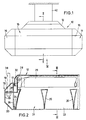
- the in Figs. 1 to 4 shown ceiling lamp has a substantially rectangular elongated housing 10 in plan, which consists of the frame 11 and the attachment 12.
- the frame 11 forms a rigid unit, which is made of metal and represents the supporting structure of the housing 10.
- Two essentially C-shaped profiles 13, 14 of mutually identical shape form the longitudinal frame parts and similarly shaped profiles 15 form the transverse frame parts.
- similarly shaped profile corners 16 are provided on the frame corners, the main surfaces (in plan view) at an angle of 45 ° to the main surfaces of the longitudinal profiles 13, 14 and the transverse profile corners 15 (see FIG. 4).
- Each of the profiles has a horizontal upper wall 17, an inclined surface 18 projecting downwardly from the outer edge of the upper wall, a side wall 19 projecting vertically downward from the lower end of the inclined surface 18, a recessed sloping surface adjoining the lower end of the side wall 19 20 and a horizontal bottom wall, which forms the edge 21 of the lower frame opening 22.
- the inclined surfaces 18 and 20 are arranged exactly one below the other. Their helix angles are the same, but opposite.
- the side walls 19 form the lateral outer boundary of the frame 11.
- each profile 13, 14 there are inwardly directed flanges 23, 24, of which the flanges 23 delimit the longitudinal upper opening 25 of the frame 11, while the flanges 24 delimit the lower frame opening 22.
- the upper frame opening 25 is smaller than the lower frame opening 22 both in the longitudinal direction and in the transverse direction.
- the profiles 15 and 16 are shaped in the same way as the profiles 13 and 14 described above. While the profiles 13, 14 and 15 are cut off at right angles at the ends, the profiles 16 are cut off at both ends at an angle of 45 °.
- form-fitting corner connectors for example made of cast aluminum or plastic, can also be used.
- the attachment 12 which closes this frame opening, is fastened to the upper frame opening 25.
- the attachment 12 consists in the illustrated embodiment of a sheet metal hood, which is painted white or mirrored on its underside. Alternatively, the attachment 12 can be made entirely or partially of translucent material.
- the attachment 12, which protrudes from the frame 11, has a flat top wall 26, from the side edges of which inclined surfaces 27 extend downward at 45 °. At the lower end of the inclined surfaces 27, vertical flanges 27a are provided, which abut against the flanges 23 of the frame 11 and are fastened to them.
- the height H A by which the attachment 12 projects beyond the frame 11 is at least 1/5 of the height H R of the frame 11 and is preferably greater than 1/4 of the frame height H R.
- the slope of the inclined surfaces 27 is at most as large as the slope of the inclined surfaces 18.
- each lamp socket 28 is fastened to a socket holder 30, which in turn is fastened inside the frame 11, but projects into the interior of the attachment 12.
- the luminous grid 31 has two longitudinal arcuate side strips 32 which, in the present exemplary embodiment, protrude into the vicinity of the top wall 26 of the attachment 12.
- the lower ends of the side strips 32 are bent outwards and upwards and form flanges 33 which are set against the flanges 24 of the frame 11 from the inside.
- the light grid is detachably connected to the frame by means of closures (not shown).
- Transversely extending intermediate webs 35 made of reflective material extend between the two side strips 32, the mutual spacing of which increases downwards.
- Each intermediate web 35 is designed in a known manner as a wedge-shaped hollow body (Fig. 2).
- the ends 35a of the intermediate webs 35 are designed as tabs which are snapped through openings in the side strips 32 in order to lock the intermediate webs 35 on the side strips 32.
- the grid 32, 35 formed from the side strips 32 and the intermediate webs 35 forms an inherently rigid grid insert which is pushed into the frame opening 22 from below and fixed by the closures.
- the intermediate webs 35 extend from the lower end of the frame opening 22 up to near the lamp 29, so that the upper web ends are in the upper third of the frame 11.
- a transverse wall 36 (FIG. 2) is fastened between the two flanges 23 and 24 of the profile 15. From this vertical Transverse wall 36 is a punched tab 37 horizontally bent outwards. Through a hole in this tab 37, the end of a pendulum tube 38 can be inserted, which is attached to the ceiling to hang the lamp.
- the frame carrier 30 is also fastened to the wall 36.
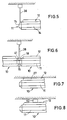
- the pendulum tube 38 projects through a breakout opening provided in the inclined surface 18 of the profile 15. When using pendulum tubes 38, the frame 11 is thus suspended at its ends projecting beyond the attachment 12. This state is shown in Fig. 5.
- the frame 11 can be used in connection with different attachments 12. It is possible to use an attachment in which only the inclined surfaces 27 are translucent, while the top wall 26 is opaque, or an attachment which is translucent overall. If the inclined surfaces 27 are translucent, a reflector device 31 is used, in which the reflectors 32 do not protrude into the vicinity of the upper wall 26, but are shorter so that the light from the lamp 29 can fall onto the inclined surfaces 27.
- the attachment 12 springs back both laterally and on the front sides relative to the frame 11, it is not visible at all when the lamp is hung sufficiently high.
- the frame 11 which has a relatively low height anyway, is given a flat and pleasing appearance.
- ballast 40 housed in the cavity between a side profile 13 and the luminaire grid 31, this is for the operation of the Fluorescent lamp 29 required ballast 40 housed.
- the ballast 40 is located essentially inside the profile 13, where there is enough space to accommodate the ballast.
- Other components or a counterweight to the ballast can be accommodated in the interior of the other sheet metal profile 14.
- FIG. 6 shows two luminaire housings 10 which are placed against one another at the end to form a light band and which are suspended at their mutually opposite ends on a common pendulum tube 38.
- the gap between the inclined surfaces 18 of the end profiles 15 is filled by a triangular adapter 41 in side view, to which the pendulum tube 38 is attached.
- the adapter 41 is in turn attached to the frame of the two lamp housings 10.
- the attachment 12 of the lamp housing 10 is fastened directly under the ceiling, the top wall 26 touching the ceiling.
- the inclined surfaces 27 of the attachment can be translucent overall or have translucent windows in order to provide ceiling lighting despite direct ceiling mounting.
- the lateral boundary walls of the attachment 12 do not have to be designed as inclined surfaces 27, but these boundary surfaces can also protrude vertically. It is only important that these lateral boundary surfaces spring back against those of the frame and are part of an attachment which is subsequently attached to the frame 11.
- the luminaire housing 10 - as in FIG. 1 - is fastened to the ceiling with spacers 42. These spacers are mounted on the top 12.
Abstract
Description
Die Erfindung betrifft eine Deckenleuchte mit einem unter einer Decke sichtbar anbringbaren Gehäuse aus einem aus Seitenwänden und Stirnwänden bestehenden Rahmen, in dem Lampenfassungen, mindestens ein Vorschaltgerät sowie ein aus Seitenleisten und Zwischenstegen bestehendes Leuchtenraster befestigt sind und der nach oben durch eine Oberwand abgeschlossen ist und unten eine von einem einwärts gerichteten Rand begrenzte Rahmenöffnung aufweist, deren Breite kleiner ist als die Rahmenbreite.The invention relates to a ceiling lamp with a housing that can be visibly attached under a ceiling, consisting of a frame consisting of side walls and end walls, in which lamp holders, at least one ballast and a lamp grid consisting of side strips and intermediate webs are fastened and which is closed at the top by an upper wall and below has a frame opening bounded by an inwardly directed edge, the width of which is smaller than the frame width.
Die üblichen Deckenleuchten mit Leuchtstofflampen weisen ein kastenförmiges Gehäuse auf, das die elektrischen und lichttechnischen Komponenten enthält und das oben durch eine Oberwand abgeschlossen und nach unten hin offen ist. Um eine blendfreie Ausleuchtung zu gewährleisten, muß das Rastergitter der Reflektorvorrichtung eine gewisse Höhe haben, wodurch die Höhe des Leuchtengehäuses wesentlich mitbestimmt wird. Das kastenförmige Leuchtengehäuse hat wegen der großen Bauhöhe ein klobiges Aussehen. Es ist auch bekannt, die Oberwand des Leuchtengehäuses als transparente Platte auszubilden, so daß ein Teil des von der Lampe ausgesandten Lichtes nach oben geleitet wird, um eine indirekte Deckenbeleuchtung zu erzielen. Wenn das Leuchtengehäuse mit relativ geringem Abstand unter der Decke angeordnet ist, wird ein Teil der Raumdecke relativ stark angestrahlt, was bei Bildschirmplätzen zu unerwünschten Lichteffekten und Reflektionen führen kann.The usual ceiling lights with fluorescent lamps have a box-shaped housing that contains the electrical and lighting components and is closed at the top by an upper wall and open at the bottom. In order to ensure glare-free illumination, the grid of the reflector device must have a certain height, as a result of which the height of the lamp housing is significantly determined. The box-shaped luminaire housing has a chunky appearance due to the large height. It is also known to design the upper wall of the lamp housing as a transparent plate, so that part of the light emitted by the lamp is directed upwards in order to achieve indirect ceiling lighting. If the luminaire housing is located at a relatively short distance below the ceiling, part of the ceiling becomes Illuminated relatively strongly, which can lead to undesirable light effects and reflections in screen spaces.
EP-A-0 110 348 beschreibt eine Deckenleuchte, bei der sich die Seitenwände des Rahmens ebenfalls über die gesamte Gehäusehöhe erstrecken und so profiliert sind, daß sie oben und unten zurückspringen. Ein solches Leuchtengehäuse wirkt schlanker und flacher, weil der obere und der untere Streifen der Seitenwand im Erscheinungsbild zurücktreten, wobei in der Regel der obere zurückspringende Streifen bei hochhängender Leuchte von dem nach außen vorstehenden mittleren Streifen verdeckt wird. Obwohl ein solches Leuchtengehäuse schlanker und eleganter wirkt als ein kastenförmiges Gehäuse, erstreckt sich der Rahmen, der das tragende Teil für die lichttechnischen und elektrischen Komponenten bildet, über die gesamte Gehäusehöhe und die den Rahmen nach oben hin abschließende Oberwand ist flach. Bei einer solchen Leuchte sind keine Variationen des Gehäuses möglich.EP-A-0 110 348 describes a ceiling lamp in which the side walls of the frame also extend over the entire height of the housing and are profiled in such a way that they spring back at the top and bottom. Such a luminaire housing appears slimmer and flatter because the upper and lower strips of the side wall recede in appearance, with the upper recessed strip usually being covered by the outwardly projecting central strip when the luminaire is hanging high. Although such a luminaire housing appears slimmer and more elegant than a box-shaped housing, the frame, which forms the supporting part for the lighting and electrical components, extends over the entire height of the housing and the top wall that closes off the frame is flat. No variations of the housing are possible with such a lamp.
Aus US-A-4 494 175 ist eine Einbauleuchte für den Einbau in abgehängte Decken bekannt, bei der ein Blechgehäuse vorgesehen ist, das aus zwei Stirnwänden und einer Oberwand besteht. In dieses seitlich offene Blechgehäuse ist ein Spiegelraster eingesetzt. Über der Oberwand des Gehäuses ist ein Installationskanal für elektrische Leitungen u.dgl. vorgesehen, der auch die Lampenfassungen enthält, welche von oben her in das Gehäuse hineinragen. Die Lampe ist im Gehäuseinnern unter der Oberwand und unter dem Installationskanal angeordnet. Eine solche Leuchte eignet sich nicht für die Anbringung unter einer Decke, weil ihr Gehäuse keine Seitenwände hat und weil ein tragender Rahmen, der abgehängt an einer Decke angebracht werden muß, erforderlich ist, um das Gehäuse zu halten. Der auf dem Gehäuse gebildete Installationskanal vergrößert nicht den Lampenraum. Er hat keine lichttechnische Bedeutung und er vergrößert die Bauhöhe der Leuchte über das lichttechnisch erforderlich Maß hinaus, um elektrische Komponenten unterbringen zu können.From US-A-4 494 175 a recessed luminaire for installation in suspended ceilings is known, in which a sheet metal housing is provided which consists of two end walls and an upper wall. A mirror grid is inserted into this laterally open sheet metal housing. An installation duct for electrical lines and the like is located above the upper wall of the housing. provided that also contains the lamp holders, which protrude from above into the housing. The lamp is located inside the housing under the top wall and under the installation duct. Such a lamp is not suitable for mounting under a ceiling because of its housing has no side walls and because a supporting frame, which must be suspended from a ceiling, is required to hold the housing. The installation channel formed on the housing does not enlarge the lamp space. It has no significance in terms of lighting technology, and it increases the overall height of the luminaire beyond what is required in terms of lighting technology in order to accommodate electrical components.
GB-A-1 185 420 beschreibt eine Aquarienleuchte mit einem trapzeförmigen Gehäuse, das auf einem am Aquariumrand montierbaren Rahmen abgestützt ist und Lampenfassungen sowie eine Leuchtstofflampe enthält. Ein Leuchtenrahmen mit umlaufenden Rahmenleisten ist dabei nicht vorgesehen. Als Deckenleuchte ist eine derartige Aquarienleuchte vom Prinzip ungeeignet.GB-A-1 185 420 describes an aquarium lamp with a trapezoidal housing which is supported on a frame which can be mounted on the edge of the aquarium and contains lamp holders and a fluorescent lamp. A luminaire frame with all-round frame strips is not provided. In principle, such an aquarium lamp is unsuitable as a ceiling lamp.
Der Erfindung liegt die Aufgabe zugrunde, eine Deckenleuchte der eingangs genannten Art zu schaffen, deren Gehäuse bei Verwendung einer Reflektorvorrichtung, die eine blendfreie Ausleuchtung bewirkt, eine schlanke Bauform von geringem Volumen hat und die unter Verwendung desselben Grundaufbaus eine Variabilität der Gehäusegestaltung zuläßt.The invention has for its object to provide a ceiling lamp of the type mentioned, the housing when using a reflector device that causes glare-free illumination, has a slim design of small volume and allows a variability of the housing design using the same basic structure.
Die Lösung dieser Aufgabe besteht erfindungsgemäß darin, daß die Oberwand des Gehäuses aus einem den Hohlraum des Rahmens nach oben hin erweiternden, an dem Rahmen befestigten Aufsatz besteht, dessen den Rahmen überragende Höhe größer ist als 1/5 der Rahmenhöhe und dessen Breite höchstens so groß ist wie die Breite der unteren Rahmenöffnung, und daß die Lampenfassungen und die daran befestigte Lampe in das Innere des Aufsatzes hineinragen.The solution to this problem is according to the invention that the upper wall of the housing consists of an upwardly widening the cavity of the frame, attached to the frame, the height of the frame is greater than 1/5 of the frame height and its width is at most as large is like the width of the lower frame opening, and that the lamp holders and the lamp attached to them protrude into the interior of the attachment.
Bei der erfindungsgemäßen Deckenleuchte ist die Höhe des Rahmens, der das tragende Bauteil für die elektrischen und lichttechnischen Komponenten bildet, kleiner als die Leuchtenhöhe. Der auf den Rahmen aufgesetzte Aufsatz, der seitlich und an den Stirnseiten gegenüber dem Rahmen zurückspringt, vergrößert das Leuchtengehäuse nach oben hin. Dadurch ist es möglich, die Leuchtstofflampe so hoch anzubringen, daß sie den Rahmen überragt. Die hohe Anordnung der Lampe ermöglicht wiederum die Verwendung höherer Stege des Rastergitters. Ferner können größere und höhere Reflektoren benutzt werden, wodurch bei gleichem Abschirmwinkel die Lichtaustrittsöffnung der Leuchte vergrößert und der Wirkungsgrad gesteigert werden kann. Durch hohe Reflektoren wird eine bessere Lichtlenkung bei scharfer Begrenzung des abgestrahlten Lichtes erreicht. Ferner besteht die Möglichkeit, die Höhe der Stege des Rastergitters zu vergrößern und dadurch einen größeren Abstand zwischen den Stegen bei Aufrechterhaltung der Blendfreiheit zu wählen.In the ceiling light according to the invention, the height of the frame, which forms the supporting component for the electrical and lighting components, is smaller than the height of the light. The attachment placed on the frame, which springs back on the sides and on the front sides opposite the frame, enlarges the lamp housing upwards. This makes it possible to mount the fluorescent lamp so high that it projects above the frame. The high arrangement of the lamp in turn enables the use of higher ridges on the grid. Furthermore, larger and higher reflectors can be used, whereby the light exit opening of the lamp can be enlarged and the efficiency can be increased with the same shielding angle. High reflectors achieve better light control with a sharp limitation of the emitted light. There is also the possibility of increasing the height of the webs of the grid and thereby choosing a larger distance between the webs while maintaining glare-free.
Bei der erfindungsgemäßen Deckenleuchte sind zahlreiche Variationen dadurch möglich, daß der Aufsatz getrennt von dem Rahmen hergestellt und erst nachträglich an diesem befestigt wird. Dadurch ist es möglich, die Leuchte mit unterschiedlichen Aufsätzen zu versehen. Vorzugsweise besteht ein Aufsatz mindestens teilweise aus transparentem Material. Da der Aufsatz nicht nur eine Oberwand, sondern auch (vertikale oder schräg verlaufende) Seitenwände hat, kann das durch den Aufsatz hindurch abgestrahlte Licht auch seitlich verteilt werden, so daß keine starke örtliche Lichtkonzentration an der Decke auftritt. Durch breitverteiltes Oberlicht unter der Decke wird verhindert, daß die Helligkeit der Decke örtlich zu groß wird. Dies ist insbesondere bei Räumen wichtig, in denen sich Bildschirmarbeitsplätze befinden.In the ceiling light according to the invention, numerous variations are possible in that the attachment is separate made of the frame and only attached to it later. This makes it possible to provide the lamp with different attachments. An attachment preferably consists at least partially of transparent material. Since the attachment not only has an upper wall, but also (vertical or inclined) side walls, the light emitted through the attachment can also be distributed laterally, so that there is no strong local light concentration on the ceiling. A broadly distributed skylight under the ceiling prevents the brightness of the ceiling from becoming too high locally. This is particularly important in rooms with VDU workstations.
Die erfindungsgemäße Deckenleuchte ermöglicht bei gleichem Grundaufbau zahlreiche Variationen. Sie kann direkt unter der Decke befestigt werden, wobei der Aufbau die Decke berührt. Selbst in diesem Fall ist eine Deckenbeleuchtung durch seitliche Lichtabstrahlung aus dem Aufsatz heraus möglich. Die Deckenleuchte kann alternativ auch mit Abstandhaltern unter der Decke angebracht oder an Pendelrohren aufgehängt werden. In jedem Fall ist es möglich, außer der Lichtabstrahlung nach unten eine Lichtabstrahlung nach oben vorzunehmen, falls ein Aufsatz verwendet wird, der ganz oder teilweise lichtdurchlässig ist. Ein besonderer Effekt wird dadurch erreicht, daß der Aufsatz, der gegenüber dem Rahmen seitlich zurückspringt, in der Regel von unten überhaupt nicht sichtbar ist und daß die Lampe seitlich durch diesen Aufsatz hindurchstrahlt, so daß der Eindruck entsteht, als sei eine seitlich abstrahlende zusätzliche Lichtquelle über dem sichtbaren Teil des Leuchtengehäuses vorhanden.The ceiling light according to the invention enables numerous variations with the same basic structure. It can be attached directly under the ceiling, with the structure touching the ceiling. Even in this case, ceiling lighting is possible through side light emission from the attachment. Alternatively, the ceiling light can also be attached with spacers under the ceiling or hung on pendulum tubes. In any case, in addition to the downward light emission, it is possible to use an upward light emission if an attachment is used that is completely or partially translucent. A special effect is achieved in that the attachment, which springs back laterally relative to the frame, is generally not visible from below at all and that the lamp shines through this attachment from the side, so that the impression is created that there is an additional light source emitting to the side above the visible part of the luminaire housing.
Im folgenden werden unter Bezugnahme auf die Zeichnungen Ausführungsbeispiele der Erfindung näher erläutert.Exemplary embodiments of the invention are explained in more detail below with reference to the drawings.
Es zeigen:
- Fig. 1
- eine Stirnansicht der Deckenleuchte,
- Fig. 2
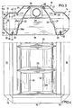
- einen Längsschnitt entlang der Linie II-II von Fig. 1,
- Fig. 3
- einen Querschnitt entlang der Linie III-III von Fig. 2,
- Fig. 4
- eine Ansicht der Leuchte von unten aus Richtung des Pfeiles IV in Fig. 1 und
- Fign. 5 bis 8
- unterschiedliche Arten der Aufhängung der Deckenleuchte.
- Fig. 1
- a front view of the ceiling lamp,
- Fig. 2
- 2 shows a longitudinal section along the line II-II of FIG. 1,
- Fig. 3
- 3 shows a cross section along the line III-III of FIG. 2,
- Fig. 4
- a view of the lamp from below from the direction of arrow IV in Fig. 1 and
- Fig. 5 to 8
- different types of suspension of the ceiling lamp.
Die in den Fign. 1 bis 4 dargestellte Deckenleuchte weist ein im Grundriß im wesentlichen rechteckförmiges langgestrecktes Gehäuse 10 auf, das aus dem Rahmen 11 und dem Aufsatz 12 besteht. Der Rahmen 11 bildet eine starre Einheit, die aus Metall hergestellt ist und die tragende Struktur des Gehäuses 10 darstellt. Zwei im wesentlichen C-förmig geformte Profile 13,14 von untereinander gleicher Form bilden die längslaufenden Rahmenteile und ähnlich geformte Profile 15 bilden die querverlaufenden Rahmenteile. Außerdem sind an den Rahmenecken ähnlich geformte Profilecken 16 vorgesehen, deren Hauptflächen (in Draufsicht) unter einem Winkel von 45° zu den Hauptflächen der längslaufenden Profile 13,14 und der querlaufenden Profilecken 15 verlaufen (s. Fig. 4).The in Figs. 1 to 4 shown ceiling lamp has a substantially rectangular
Jedes der Profile weist eine horizontale Oberwand 17, eine von der äußeren Kante der Oberwand schräg nach unten abstehende Schrägfläche 18, eine von dem unteren Ende der Schrägfläche 18 vertikal nach unten ragende Seitenwand 19, eine sich an das untere Ende der Seitenwand 19 anschließende zurückspringende Schrägfläche 20 und eine horizontale Bodenwand, die den Rand 21 der unteren Rahmenöffnung 22 bildet, auf. Die Schrägflächen 18 und 20 sind genau untereinander angeordnet. Ihre Schrägwinkel sind gleich, jedoch entgegengesetzt. Die Seitenwände 19 bilden die seitliche äußere Begrenzung des Rahmens 11.Each of the profiles has a horizontal
An den beiden Enden eines jeden Profils 13,14 sind nach innen gerichtete Flansche 23, 24 vorgesehen, von denen die Flansche 23 die längslaufende obere Öffnung 25 des Rahmens 11 begrenzen, während die Flansche 24 die untere Rahmenöffnung 22 begrenzen. Die obere Rahmenöffnung 25 ist sowohl in Längsrichtung als auch in Querrichtung kleiner als die untere Rahmenöffnung 22.At the two ends of each
Die Profile 15 und 16 sind in gleicher Weise geformt wie die oben beschriebenen Profile 13 und 14. Während die Profile 13, 14 und 15 an den Enden jeweils rechtwinklig abgeschnitten sind, sind die Profile 16 an beiden Enden unter einem Winkel von 45° abgeschnitten. Anstelle der Profile 16 können auch formlich angepaßte Eckverbinder, z.B. aus Alu-Guß oder Kunststoff, eingesetzt werden.The
An der oberen Rahmenöffnung 25 ist der Aufsatz 12 befestigt, der diese Rahmenöffnung verschließt. Der Aufsatz 12 besteht bei dem dargestellten Ausführungsbeispiel aus einer Blechhaube, die an ihrer Unterseite weiß lackiert oder verspiegelt ist. Alternativ kann der Aufsatz 12 ganz oder teilweise aus lichtdurchlässigem Material bestehen. Der Aufsatz 12, der von dem Rahmen 11 aufragt, weist eine ebene Oberwand 26 auf, von deren Seitenrändern sich Schrägflächen 27 unter 45° nach unten erstrecken. An den unteren Ende der Schrägflächen 27 sind vertikale Flansche 27a vorgesehen, die innen an den Flanschen 23 des Rahmens 11 anliegen und an diesen befestigt sind.The
Die Höhe HA, um die der Aufsatz 12 den Rahmen 11 überragt, beträgt mindestens 1/5 der Höhe HR des Rahmens 11 und ist vorzugsweise größer als 1/4 der Rahmenhöhe HR. Die Steilheit der Schrägflächen 27 ist maximal so groß wie die Steilheit der Schrägflächen 18.The height H A by which the
Durch das Innere des Aufsatzes 12 wird der Hohlraum des Rahmens 11 nach oben hin erweitert. Die Lampenfassungen 28, an denen die Enden der langgestreckten Leuchtstofflampe 29 befestigt und kontaktiert sind, ragen in den Aufsatz 12 hinein, so daß die Lampe 29 die Oberwand 17 des Rahmens 11 überragt und sich zu einem wesentlichen Teil - bei dem vorliegenden Ausführungsbeispiel zum überwiegenden Teil - im Inneren des Aufsatzes 12 befindet. Jede Lampenfassung 28 ist gemäß Fig. 2 an einem Fassungshalter 30 befestigt, der seinerseits im Inneren des Rahmens 11 befestigt ist, jedoch in das Innere des Aufsatzes 12 hineinragt.The cavity of the
Das Leuchtraster 31 weist zwei längslaufende bogenförmige Seitenleisten 32 auf, die bei dem vorliegenden Ausführungsbeispiel bis in die Nähe der Oberwand 26 des Aufsatzes 12 ragen. Die unteren Ende der Seitenleisten 32 sind nach außen und oben umgebogen und bilden Flansche 33, die von innen gegen die Flansche 24 des Rahmens 11 gesetzt sind. Das Leuchtenraster ist durch (nicht dargestellte) Verschlüsse mit dem Rahmen lösbar verbunden.The
Zwischen den beiden Seitenleisten 32, deren gegenseitiger Abstand sich nach unten hin vergrößert, erstrecken sich querlaufende Zwischenstege 35 aus reflektierendem Material. Jeder Zwischensteg 35 ist in bekannter Weise als keilförmiger Hohlkörper ausgebildet (Fig. 2). Die Enden 35a der Zwischenstege 35 sind als Laschen ausgebildet, die durch Durchbrüche der Seitenleisten 32 einrastend hindurchgesteckt sind, um die Zwischenstege 35 an den Seitenleisten 32 zu verriegeln. Das aus den Seitenleisten 32 und den Zwischenstegen 35 gebildete Rastergitter 32,35 bildet einen in sich starren Rastereinsatz, der von unten her in die Rahmenöffnung 22 eingeschoben und durch die Verschlüsse fixiert wird.Transversely extending
Wie aus Fig. 3 erkennbar ist, erstrecken sich die Zwischenstege 35 vom unteren Ende der Rahmenöffnung 22 aus bis in die Nähe der Lampe 29 nach oben, so daß die oberen Stegenden sich im oberen Drittel des Rahmens 11 befinden.As can be seen from FIG. 3, the
Im Inneren der stirnseitigen Profile 15 ist jeweils eine Querwand 36 (Fig. 2) zwischen den beiden Flanschen 23 und 24 des Profils 15 befestigt. Aus dieser vertikalen Querwand 36 ist eine ausgestanzte Lasche 37 horizontal nach außen abgebogen. Durch ein Loch dieser Lasche 37 kann das Ende eines Pendelrohres 38 hindurchgesteckt werden, das an der Decke befestigt ist, um die Leuchte aufzuhängen. An der Wand 36 ist außerdem der Fassungsträger 30 befestigt. Das Pendelrohr 38 ragt durch eine in der Schrägfläche 18 des Profils 15 vorgesehene Ausbrechöffnung hindurch. Bei der Benutzung von Pendelrohren 38 wird also der Rahmen 11 an seinen den Aufsatz 12 überragenden Enden aufgehängt. Dieser Zustand ist in Fig. 5 dargestellt.In the interior of the end profiles 15, a transverse wall 36 (FIG. 2) is fastened between the two
Der Rahmen 11 kann in Verbindung mit unterschiedlichen Aufsätzen 12 benutzt werden. Es ist möglich, einen Aufsatz zu verwenden, bei dem nur die Schrägflächen 27 lichtdurchlässig sind, während die Oberwand 26 lichtundurchlässig ist, oder einen Aufsatz, der insgesamt lichtdurchlässig ist. Wenn die Schrägflächen 27 lichtdurchlässig sind, wird eine Reflektorvorrichtung 31 benutzt, bei der die Reflektoren 32 nicht bis in die Nähe der Oberwand 26 ragen, sondern kürzer sind, damit das Licht der Lampe 29 auf die Schrägflächen 27 fallen kann.The
Da der Aufsatz 12 gegenüber dem Rahmen 11 sowohl seitlich als auch an den Stirnseiten zurückspringt, ist er bei hinreichend hoch aufgehängter Leuchte überhaupt nicht sichtbar. Durch die Verwendung der Profile mit den Schrägflächen 18 und 20 erhält der Rahmen 11, der ohnehin eine relativ geringe Höhe hat, ein flaches und gefälliges Aussehen.Since the
In dem Hohlraum zwischen einem seitlichen Profil 13 und dem Leuchtenraster 31 ist das für den Betrieb der Leuchtstofflampe 29 benötigte Vorschaltgerät 40 untergebracht. Das Vorschaltgerät 40 befindet sich im wesentlichen im Inneren des Profils 13, wo genügend Raum zur Aufnahme des Vorschaltgerätes zur Verfügung steht. Im Inneren des anderen Blechprofils 14 können andere Komponenten oder ein Gegengewicht zum Vorschaltgerät untergebracht werden.In the cavity between a
Fig. 6 zeigt zwei zur Bildung eines Lichtbandes stirnseitig gegeneinandergesetzte Leuchtengehäuse 10, die an ihren gegeneinandergerichteten Enden an einem gemeinsamen Pendelrohr 38 aufgehängt sind. Der Spalt zwischen den Schrägflächen 18 der stirnseitigen Profile 15 ist durch einen in Seitenansicht dreieckförmigen Adapter 41 ausgefüllt, an dem das Pendelrohr 38 befestigt ist. Der Adapter 41 ist seinerseits an den Rahmen der beiden Leuchtengehäuse 10 befestigt.FIG. 6 shows two
Bei der Anwendungsform von Fig. 7 ist der Aufsatz 12 des Lampengehäuses 10 unmittelbar unter der Decke befestigt, wobei die Oberwand 26 die Decke berührt. In diesem Fall können die Schrägflächen 27 des Aufsatzes insgesamt lichtdurchlässig sein oder lichtdurchlässige Fenster aufweisen, um trotz direkter Deckenmontage noch eine Deckenbeleuchtung zu bewirken. Grundsätzlich müssen die seitlichen Begrenzungswände des Aufsatzes 12 nicht als Schrägflächen 27 ausgebildet sein, sondern diese Begrenzungsflächen können auch senkrecht aufragen. Wichtig ist nur, daß diese seitlichen Begrenzungsflächen gegenüber denjenigen des Rahmens zurückspringen und Bestandteil eines Aufsatzes sind, der an dem Rahmen 11 nachträglich befestigt ist.7, the
Bei der Anbringungsart von Fig. 8 ist das Leuchtengehäuse 10 - ebenso wie in Fig. 1 - mit Abstandhaltern 42 an der Decke befestigt. Diese Abstandhalter sind an dem Aufsatz 12 montiert.8, the luminaire housing 10 - as in FIG. 1 - is fastened to the ceiling with
Claims (9)
- A ceiling luminaire with a housing (10) for being mounted visibly below a ceiling, which housing comprises a frame (11) of lateral walls and end walls, in which frame there are mounted lamp sockets (28), at least one ballast (40) and a louver of lateral bars (32) and intermediate ribs (35), said frame being closed at the top by a top wall and having a frame opening (22) at the bottom, which is defined by an inward directed edge (21), the width of said opening being less than the width of said frame,
characterised in
that the top wall of said housing (10) consists of a top mounting (12) mounted on said frame (11) and enlarging the cavity of said frame (11) to the top, the height (HA) of said top mounting extending beyond the height of said frame (11) being larger than 1/5 of the frame height (HR) and the width of said top mounting being as large as the width of the bottom frame opening (23), at most, and that said lamp sockets (28) and the lamps (29) mounted therein protrude into the interior of said top mounting (12). - Ceiling mounted luminaire as defined in claim 1, characterised in that cavities for receiving a ballast (40) and other components are provided between said side walls (19) of said frame (11) and said longitudinally extending lateral bars (32) of said louver (31).
- Ceiling mounted luminaire as defined in claim 1 or 2, characterised in that said lateral bars (32) of said louver protrude into the interior of said top mounting (12).
- Ceiling mounted luminaire as defined in one of claims 1 to 3, characterised in that said frame (11) has a top wall (17) passing into the adjoining side wall (19) via an inclined surface (13).
- Ceiling mounted luminaire as defined in claim 4, characterised in that said top mounting (12) has lateral inclined surfaces (27), the angle of inclination of which is not steeper than that of the inclined surfaces (18) of said frame (11).
- Ceiling mounted luminaire as defined in one of claims 1 to 5, characterised in that said top mounting (12) consists at least in part of tranparent material.
- Ceiling mounted luminaire as defined in claim 6, characterised in that the transparent parts ar provided with light-directing structures.
- Ceiling mounted luminaire as defined in one of claims 1 to 7, characterised in that the end walls of said frame (11) project with respect to those of said top mounting (12) and that, in said projecting part on the inside of said frame (11), there is provided a retaining device (37) for mounting a pendulum support (38) projecting into said frame from above.
- Ceiling mounted luminaire as defined in one of claims 1 to 8, characterised in that said top mounting (12) is replaceably mounted on said frame (11).
Priority Applications (1)
| Application Number | Priority Date | Filing Date | Title |
|---|---|---|---|
| AT86113013T ATE71450T1 (en) | 1985-11-12 | 1986-09-20 | CEILING LIGHT. |
Applications Claiming Priority (2)
| Application Number | Priority Date | Filing Date | Title |
|---|---|---|---|
| DE8531886U | 1985-11-12 | ||
| DE8531886U DE8531886U1 (en) | 1985-11-12 | 1985-11-12 | Ceiling lamp |
Publications (3)
| Publication Number | Publication Date |
|---|---|
| EP0222115A2 EP0222115A2 (en) | 1987-05-20 |
| EP0222115A3 EP0222115A3 (en) | 1989-04-26 |
| EP0222115B1 true EP0222115B1 (en) | 1992-01-08 |
Family
ID=6787159
Family Applications (1)
| Application Number | Title | Priority Date | Filing Date |
|---|---|---|---|
| EP86113013A Expired - Lifetime EP0222115B1 (en) | 1985-11-12 | 1986-09-20 | Ceiling lighting fixture |
Country Status (3)
| Country | Link |
|---|---|
| EP (1) | EP0222115B1 (en) |
| AT (1) | ATE71450T1 (en) |
| DE (2) | DE8531886U1 (en) |
Families Citing this family (7)
| Publication number | Priority date | Publication date | Assignee | Title |
|---|---|---|---|---|
| DE8632021U1 (en) * | 1986-11-29 | 1987-01-29 | Trilux-Lenze Gmbh + Co Kg, 5760 Arnsberg, De | |
| DE3841518A1 (en) * | 1988-12-09 | 1990-06-13 | Trilux Lenze Gmbh & Co Kg | MIRROR LAMP |
| DE3900202A1 (en) * | 1989-01-05 | 1990-07-12 | Thorn Licht Gmbh | GRID LAMP EQUIPPED WITH A STAINLESS FLUORESCENT LAMP |
| DE4243659A1 (en) * | 1992-12-23 | 1994-06-30 | Licentia Gmbh | Metal grid for a lamp |
| DE4411206C2 (en) * | 1994-03-31 | 2002-06-13 | Zumtobel Licht Gmbh Dornbirn | Slat with prism structure for louvre luminaires |
| DE29513723U1 (en) * | 1995-08-26 | 1995-10-26 | Trilux Lenze Gmbh & Co Kg | lamp |
| US6565238B1 (en) * | 2000-06-23 | 2003-05-20 | H. E. Williams, Inc. | Fluorescent light fixture with lateral ballast |
Family Cites Families (5)
| Publication number | Priority date | Publication date | Assignee | Title |
|---|---|---|---|---|
| FR1002842A (en) * | 1949-12-16 | 1952-03-11 | Saunier Duval | Light bar for work tables |
| CA687187A (en) * | 1958-01-16 | 1964-05-26 | C. Winkler Frederic | Luminaire |
| GB1185420A (en) * | 1967-12-16 | 1970-03-25 | Meyer & Co Alu Therm W | Improvements in or relating to Aquarium Lighting Systems. |
| US3788206A (en) * | 1972-08-21 | 1974-01-29 | G Mulvey | Modular ceiling construction |
| US4494175A (en) * | 1984-01-09 | 1985-01-15 | Gte Products Corporation | Recessed lighting fixture with improved louver mounting |
-
1985
- 1985-11-12 DE DE8531886U patent/DE8531886U1/en not_active Expired
-
1986
- 1986-09-20 DE DE8686113013T patent/DE3683353D1/en not_active Expired - Lifetime
- 1986-09-20 AT AT86113013T patent/ATE71450T1/en not_active IP Right Cessation
- 1986-09-20 EP EP86113013A patent/EP0222115B1/en not_active Expired - Lifetime
Also Published As
| Publication number | Publication date |
|---|---|
| DE3683353D1 (en) | 1992-02-20 |
| DE8531886U1 (en) | 1986-08-28 |
| EP0222115A2 (en) | 1987-05-20 |
| ATE71450T1 (en) | 1992-01-15 |
| EP0222115A3 (en) | 1989-04-26 |
Similar Documents
| Publication | Publication Date | Title |
|---|---|---|
| EP0898686B2 (en) | Lighting fitting with a basic unit as support for at least one lamp | |
| DE3644335C2 (en) | System luminaire for generating light band-like lighting structures | |
| DE3147510A1 (en) | SUSPENDED CEILING WITH INTEGRATED LIGHTING BODY, LIGHTING BODY AND METHOD FOR CONSTRUCTION OF A SUSPENDED CEILING WITH LIGHTING BODY | |
| EP2138873A1 (en) | Lamp with at least one translucent cover | |
| EP1734300B2 (en) | Indoor lamp | |
| DE2049775C3 (en) | Trough-shaped curtain rail box | |
| EP0897511B1 (en) | Light fixture with a linear lighting field, suitable for forming lighting trunking | |
| EP0222115B1 (en) | Ceiling lighting fixture | |
| DE19719184C1 (en) | lamp | |
| EP0726420B1 (en) | Lighting fixture, especially for humid space, with a two-part closed housing | |
| EP1495258A2 (en) | Flat lighting fixture | |
| EP0795719B1 (en) | Modular lamp unit | |
| DE2747346C2 (en) | ||
| DE102012207540A1 (en) | lamp | |
| DE4143328A1 (en) | Work place lamp for mid-height illumination - uses reflectors snapped into housing from below and glass retained by own weight | |
| EP1045196A2 (en) | Lighting assembly with a supporting structure | |
| EP1918635B1 (en) | Ambience lamp | |
| EP3364099B1 (en) | Modular lamp with direct and indirect share | |
| EP0760449B1 (en) | Lighting fixture | |
| DE102019117504A1 (en) | lamp | |
| EP0193014B1 (en) | Wall-mounted bed light fixture | |
| EP1043541A2 (en) | Lighting assembly comprising a plurality of frameless, light pervious covers | |
| DE102004035461A1 (en) | Multifunctional compact light has long light with hollow side wings light window and flexible distance pieces | |
| DE202010012890U1 (en) | lamp | |
| CH636940A5 (en) | Surface-mounting luminaire with detachable shade |
Legal Events
| Date | Code | Title | Description |
|---|---|---|---|
| PUAI | Public reference made under article 153(3) epc to a published international application that has entered the european phase |
Free format text: ORIGINAL CODE: 0009012 |
|
| AK | Designated contracting states |
Kind code of ref document: A2 Designated state(s): AT BE DE FR GB IT NL |
|
| PUAL | Search report despatched |
Free format text: ORIGINAL CODE: 0009013 |
|
| AK | Designated contracting states |
Kind code of ref document: A3 Designated state(s): AT BE DE FR GB IT NL |
|
| 17P | Request for examination filed |
Effective date: 19890530 |
|
| 17Q | First examination report despatched |
Effective date: 19900727 |
|
| GRAA | (expected) grant |
Free format text: ORIGINAL CODE: 0009210 |
|
| AK | Designated contracting states |
Kind code of ref document: B1 Designated state(s): AT BE DE FR GB IT NL |
|
| REF | Corresponds to: |
Ref document number: 71450 Country of ref document: AT Date of ref document: 19920115 Kind code of ref document: T |
|
| ITF | It: translation for a ep patent filed |
Owner name: ING. A. GIAMBROCONO & C. S.R.L. |
|
| GBT | Gb: translation of ep patent filed (gb section 77(6)(a)/1977) | ||
| ET | Fr: translation filed | ||
| REF | Corresponds to: |
Ref document number: 3683353 Country of ref document: DE Date of ref document: 19920220 |
|
| PGFP | Annual fee paid to national office [announced via postgrant information from national office to epo] |
Ref country code: GB Payment date: 19920814 Year of fee payment: 7 |
|
| PGFP | Annual fee paid to national office [announced via postgrant information from national office to epo] |
Ref country code: BE Payment date: 19920903 Year of fee payment: 7 |
|
| PGFP | Annual fee paid to national office [announced via postgrant information from national office to epo] |
Ref country code: AT Payment date: 19920925 Year of fee payment: 7 |
|
| PGFP | Annual fee paid to national office [announced via postgrant information from national office to epo] |
Ref country code: NL Payment date: 19920930 Year of fee payment: 7 Ref country code: FR Payment date: 19920930 Year of fee payment: 7 |
|
| PGFP | Annual fee paid to national office [announced via postgrant information from national office to epo] |
Ref country code: DE Payment date: 19921106 Year of fee payment: 7 |
|
| PLBE | No opposition filed within time limit |
Free format text: ORIGINAL CODE: 0009261 |
|
| STAA | Information on the status of an ep patent application or granted ep patent |
Free format text: STATUS: NO OPPOSITION FILED WITHIN TIME LIMIT |
|
| 26N | No opposition filed | ||
| PG25 | Lapsed in a contracting state [announced via postgrant information from national office to epo] |
Ref country code: GB Effective date: 19930920 Ref country code: AT Effective date: 19930920 |
|
| PG25 | Lapsed in a contracting state [announced via postgrant information from national office to epo] |
Ref country code: BE Effective date: 19930930 |
|
| BERE | Be: lapsed |
Owner name: TRILUX-LENZE G.M.B.H. & CO. K.G. Effective date: 19930930 |
|
| PG25 | Lapsed in a contracting state [announced via postgrant information from national office to epo] |
Ref country code: NL Effective date: 19940401 |
|
| NLV4 | Nl: lapsed or anulled due to non-payment of the annual fee | ||
| GBPC | Gb: european patent ceased through non-payment of renewal fee |
Effective date: 19930920 |
|
| PG25 | Lapsed in a contracting state [announced via postgrant information from national office to epo] |
Ref country code: FR Free format text: LAPSE BECAUSE OF NON-PAYMENT OF DUE FEES Effective date: 19940531 |
|
| PG25 | Lapsed in a contracting state [announced via postgrant information from national office to epo] |
Ref country code: DE Effective date: 19940601 |
|
| REG | Reference to a national code |
Ref country code: FR Ref legal event code: ST |
|
| PG25 | Lapsed in a contracting state [announced via postgrant information from national office to epo] |
Ref country code: IT Free format text: LAPSE BECAUSE OF NON-PAYMENT OF DUE FEES;WARNING: LAPSES OF ITALIAN PATENTS WITH EFFECTIVE DATE BEFORE 2007 MAY HAVE OCCURRED AT ANY TIME BEFORE 2007. THE CORRECT EFFECTIVE DATE MAY BE DIFFERENT FROM THE ONE RECORDED. Effective date: 20050920 |