EP0222115B1 - Lampe de plafond - Google Patents
Lampe de plafond Download PDFInfo
- Publication number
- EP0222115B1 EP0222115B1 EP86113013A EP86113013A EP0222115B1 EP 0222115 B1 EP0222115 B1 EP 0222115B1 EP 86113013 A EP86113013 A EP 86113013A EP 86113013 A EP86113013 A EP 86113013A EP 0222115 B1 EP0222115 B1 EP 0222115B1
- Authority
- EP
- European Patent Office
- Prior art keywords
- frame
- ceiling
- luminaire
- lamp
- housing
- Prior art date
- Legal status (The legal status is an assumption and is not a legal conclusion. Google has not performed a legal analysis and makes no representation as to the accuracy of the status listed.)
- Expired - Lifetime
Links
- 239000000463 material Substances 0.000 claims description 3
- 238000005286 illumination Methods 0.000 abstract description 3
- 239000012780 transparent material Substances 0.000 abstract description 2
- 229910052751 metal Inorganic materials 0.000 description 5
- 239000002184 metal Substances 0.000 description 5
- 238000009434 installation Methods 0.000 description 4
- 125000006850 spacer group Chemical group 0.000 description 3
- 238000005516 engineering process Methods 0.000 description 2
- 101100390736 Danio rerio fign gene Proteins 0.000 description 1
- 101100390738 Mus musculus Fign gene Proteins 0.000 description 1
- 229910052782 aluminium Inorganic materials 0.000 description 1
- XAGFODPZIPBFFR-UHFFFAOYSA-N aluminium Chemical compound [Al] XAGFODPZIPBFFR-UHFFFAOYSA-N 0.000 description 1
- 230000000694 effects Effects 0.000 description 1
- 230000003760 hair shine Effects 0.000 description 1
- 230000001795 light effect Effects 0.000 description 1
- 239000000725 suspension Substances 0.000 description 1
Images
Classifications
-
- F—MECHANICAL ENGINEERING; LIGHTING; HEATING; WEAPONS; BLASTING
- F21—LIGHTING
- F21S—NON-PORTABLE LIGHTING DEVICES; SYSTEMS THEREOF; VEHICLE LIGHTING DEVICES SPECIALLY ADAPTED FOR VEHICLE EXTERIORS
- F21S8/00—Lighting devices intended for fixed installation
- F21S8/04—Lighting devices intended for fixed installation intended only for mounting on a ceiling or the like overhead structures
- F21S8/06—Lighting devices intended for fixed installation intended only for mounting on a ceiling or the like overhead structures by suspension
-
- F—MECHANICAL ENGINEERING; LIGHTING; HEATING; WEAPONS; BLASTING
- F21—LIGHTING
- F21V—FUNCTIONAL FEATURES OR DETAILS OF LIGHTING DEVICES OR SYSTEMS THEREOF; STRUCTURAL COMBINATIONS OF LIGHTING DEVICES WITH OTHER ARTICLES, NOT OTHERWISE PROVIDED FOR
- F21V23/00—Arrangement of electric circuit elements in or on lighting devices
- F21V23/02—Arrangement of electric circuit elements in or on lighting devices the elements being transformers, impedances or power supply units, e.g. a transformer with a rectifier
-
- F—MECHANICAL ENGINEERING; LIGHTING; HEATING; WEAPONS; BLASTING
- F21—LIGHTING
- F21Y—INDEXING SCHEME ASSOCIATED WITH SUBCLASSES F21K, F21L, F21S and F21V, RELATING TO THE FORM OR THE KIND OF THE LIGHT SOURCES OR OF THE COLOUR OF THE LIGHT EMITTED
- F21Y2103/00—Elongate light sources, e.g. fluorescent tubes
Definitions
- the invention relates to a ceiling lamp with a housing that can be visibly attached under a ceiling, consisting of a frame consisting of side walls and end walls, in which lamp holders, at least one ballast and a lamp grid consisting of side strips and intermediate webs are fastened and which is closed at the top by an upper wall and below has a frame opening bounded by an inwardly directed edge, the width of which is smaller than the frame width.
- the usual ceiling lights with fluorescent lamps have a box-shaped housing that contains the electrical and lighting components and is closed at the top by an upper wall and open at the bottom.
- the grid of the reflector device In order to ensure glare-free illumination, the grid of the reflector device must have a certain height, as a result of which the height of the lamp housing is significantly determined.
- the box-shaped luminaire housing has a chunky appearance due to the large height. It is also known to design the upper wall of the lamp housing as a transparent plate, so that part of the light emitted by the lamp is directed upwards in order to achieve indirect ceiling lighting. If the luminaire housing is located at a relatively short distance below the ceiling, part of the ceiling becomes Illuminated relatively strongly, which can lead to undesirable light effects and reflections in screen spaces.
- EP-A-0 110 348 describes a ceiling lamp in which the side walls of the frame also extend over the entire height of the housing and are profiled in such a way that they spring back at the top and bottom.
- Such a luminaire housing appears slimmer and flatter because the upper and lower strips of the side wall recede in appearance, with the upper recessed strip usually being covered by the outwardly projecting central strip when the luminaire is hanging high.
- the frame which forms the supporting part for the lighting and electrical components, extends over the entire height of the housing and the top wall that closes off the frame is flat. No variations of the housing are possible with such a lamp.
- a recessed luminaire for installation in suspended ceilings in which a sheet metal housing is provided which consists of two end walls and an upper wall. A mirror grid is inserted into this laterally open sheet metal housing.
- An installation duct for electrical lines and the like is located above the upper wall of the housing. provided that also contains the lamp holders, which protrude from above into the housing.
- the lamp is located inside the housing under the top wall and under the installation duct.
- Such a lamp is not suitable for mounting under a ceiling because of its housing has no side walls and because a supporting frame, which must be suspended from a ceiling, is required to hold the housing.
- the installation channel formed on the housing does not enlarge the lamp space. It has no significance in terms of lighting technology, and it increases the overall height of the luminaire beyond what is required in terms of lighting technology in order to accommodate electrical components.
- GB-A-1 185 420 describes an aquarium lamp with a trapezoidal housing which is supported on a frame which can be mounted on the edge of the aquarium and contains lamp holders and a fluorescent lamp. A luminaire frame with all-round frame strips is not provided. In principle, such an aquarium lamp is unsuitable as a ceiling lamp.
- the invention has for its object to provide a ceiling lamp of the type mentioned, the housing when using a reflector device that causes glare-free illumination, has a slim design of small volume and allows a variability of the housing design using the same basic structure.
- the upper wall of the housing consists of an upwardly widening the cavity of the frame, attached to the frame, the height of the frame is greater than 1/5 of the frame height and its width is at most as large is like the width of the lower frame opening, and that the lamp holders and the lamp attached to them protrude into the interior of the attachment.
- the height of the frame which forms the supporting component for the electrical and lighting components, is smaller than the height of the light.
- the attachment placed on the frame which springs back on the sides and on the front sides opposite the frame, enlarges the lamp housing upwards.
- the high arrangement of the lamp in turn enables the use of higher ridges on the grid.
- larger and higher reflectors can be used, whereby the light exit opening of the lamp can be enlarged and the efficiency can be increased with the same shielding angle.
- High reflectors achieve better light control with a sharp limitation of the emitted light.
- the attachment is separate made of the frame and only attached to it later. This makes it possible to provide the lamp with different attachments.
- An attachment preferably consists at least partially of transparent material. Since the attachment not only has an upper wall, but also (vertical or inclined) side walls, the light emitted through the attachment can also be distributed laterally, so that there is no strong local light concentration on the ceiling. A broadly distributed skylight under the ceiling prevents the brightness of the ceiling from becoming too high locally. This is particularly important in rooms with VDU workstations.
- the ceiling light according to the invention enables numerous variations with the same basic structure. It can be attached directly under the ceiling, with the structure touching the ceiling. Even in this case, ceiling lighting is possible through side light emission from the attachment. Alternatively, the ceiling light can also be attached with spacers under the ceiling or hung on pendulum tubes. In any case, in addition to the downward light emission, it is possible to use an upward light emission if an attachment is used that is completely or partially translucent. A special effect is achieved in that the attachment, which springs back laterally relative to the frame, is generally not visible from below at all and that the lamp shines through this attachment from the side, so that the impression is created that there is an additional light source emitting to the side above the visible part of the luminaire housing.
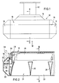
- the in Figs. 1 to 4 shown ceiling lamp has a substantially rectangular elongated housing 10 in plan, which consists of the frame 11 and the attachment 12.
- the frame 11 forms a rigid unit, which is made of metal and represents the supporting structure of the housing 10.
- Two essentially C-shaped profiles 13, 14 of mutually identical shape form the longitudinal frame parts and similarly shaped profiles 15 form the transverse frame parts.
- similarly shaped profile corners 16 are provided on the frame corners, the main surfaces (in plan view) at an angle of 45 ° to the main surfaces of the longitudinal profiles 13, 14 and the transverse profile corners 15 (see FIG. 4).
- Each of the profiles has a horizontal upper wall 17, an inclined surface 18 projecting downwardly from the outer edge of the upper wall, a side wall 19 projecting vertically downward from the lower end of the inclined surface 18, a recessed sloping surface adjoining the lower end of the side wall 19 20 and a horizontal bottom wall, which forms the edge 21 of the lower frame opening 22.
- the inclined surfaces 18 and 20 are arranged exactly one below the other. Their helix angles are the same, but opposite.
- the side walls 19 form the lateral outer boundary of the frame 11.
- each profile 13, 14 there are inwardly directed flanges 23, 24, of which the flanges 23 delimit the longitudinal upper opening 25 of the frame 11, while the flanges 24 delimit the lower frame opening 22.
- the upper frame opening 25 is smaller than the lower frame opening 22 both in the longitudinal direction and in the transverse direction.
- the profiles 15 and 16 are shaped in the same way as the profiles 13 and 14 described above. While the profiles 13, 14 and 15 are cut off at right angles at the ends, the profiles 16 are cut off at both ends at an angle of 45 °.
- form-fitting corner connectors for example made of cast aluminum or plastic, can also be used.
- the attachment 12 which closes this frame opening, is fastened to the upper frame opening 25.
- the attachment 12 consists in the illustrated embodiment of a sheet metal hood, which is painted white or mirrored on its underside. Alternatively, the attachment 12 can be made entirely or partially of translucent material.
- the attachment 12, which protrudes from the frame 11, has a flat top wall 26, from the side edges of which inclined surfaces 27 extend downward at 45 °. At the lower end of the inclined surfaces 27, vertical flanges 27a are provided, which abut against the flanges 23 of the frame 11 and are fastened to them.
- the height H A by which the attachment 12 projects beyond the frame 11 is at least 1/5 of the height H R of the frame 11 and is preferably greater than 1/4 of the frame height H R.
- the slope of the inclined surfaces 27 is at most as large as the slope of the inclined surfaces 18.
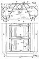
- each lamp socket 28 is fastened to a socket holder 30, which in turn is fastened inside the frame 11, but projects into the interior of the attachment 12.
- the luminous grid 31 has two longitudinal arcuate side strips 32 which, in the present exemplary embodiment, protrude into the vicinity of the top wall 26 of the attachment 12.
- the lower ends of the side strips 32 are bent outwards and upwards and form flanges 33 which are set against the flanges 24 of the frame 11 from the inside.
- the light grid is detachably connected to the frame by means of closures (not shown).
- Transversely extending intermediate webs 35 made of reflective material extend between the two side strips 32, the mutual spacing of which increases downwards.
- Each intermediate web 35 is designed in a known manner as a wedge-shaped hollow body (Fig. 2).
- the ends 35a of the intermediate webs 35 are designed as tabs which are snapped through openings in the side strips 32 in order to lock the intermediate webs 35 on the side strips 32.
- the grid 32, 35 formed from the side strips 32 and the intermediate webs 35 forms an inherently rigid grid insert which is pushed into the frame opening 22 from below and fixed by the closures.
- the intermediate webs 35 extend from the lower end of the frame opening 22 up to near the lamp 29, so that the upper web ends are in the upper third of the frame 11.
- a transverse wall 36 (FIG. 2) is fastened between the two flanges 23 and 24 of the profile 15. From this vertical Transverse wall 36 is a punched tab 37 horizontally bent outwards. Through a hole in this tab 37, the end of a pendulum tube 38 can be inserted, which is attached to the ceiling to hang the lamp.
- the frame carrier 30 is also fastened to the wall 36.
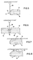
- the pendulum tube 38 projects through a breakout opening provided in the inclined surface 18 of the profile 15. When using pendulum tubes 38, the frame 11 is thus suspended at its ends projecting beyond the attachment 12. This state is shown in Fig. 5.
- the frame 11 can be used in connection with different attachments 12. It is possible to use an attachment in which only the inclined surfaces 27 are translucent, while the top wall 26 is opaque, or an attachment which is translucent overall. If the inclined surfaces 27 are translucent, a reflector device 31 is used, in which the reflectors 32 do not protrude into the vicinity of the upper wall 26, but are shorter so that the light from the lamp 29 can fall onto the inclined surfaces 27.
- the attachment 12 springs back both laterally and on the front sides relative to the frame 11, it is not visible at all when the lamp is hung sufficiently high.
- the frame 11 which has a relatively low height anyway, is given a flat and pleasing appearance.
- ballast 40 housed in the cavity between a side profile 13 and the luminaire grid 31, this is for the operation of the Fluorescent lamp 29 required ballast 40 housed.
- the ballast 40 is located essentially inside the profile 13, where there is enough space to accommodate the ballast.
- Other components or a counterweight to the ballast can be accommodated in the interior of the other sheet metal profile 14.
- FIG. 6 shows two luminaire housings 10 which are placed against one another at the end to form a light band and which are suspended at their mutually opposite ends on a common pendulum tube 38.
- the gap between the inclined surfaces 18 of the end profiles 15 is filled by a triangular adapter 41 in side view, to which the pendulum tube 38 is attached.
- the adapter 41 is in turn attached to the frame of the two lamp housings 10.
- the attachment 12 of the lamp housing 10 is fastened directly under the ceiling, the top wall 26 touching the ceiling.
- the inclined surfaces 27 of the attachment can be translucent overall or have translucent windows in order to provide ceiling lighting despite direct ceiling mounting.
- the lateral boundary walls of the attachment 12 do not have to be designed as inclined surfaces 27, but these boundary surfaces can also protrude vertically. It is only important that these lateral boundary surfaces spring back against those of the frame and are part of an attachment which is subsequently attached to the frame 11.
- the luminaire housing 10 - as in FIG. 1 - is fastened to the ceiling with spacers 42. These spacers are mounted on the top 12.
Landscapes
- Engineering & Computer Science (AREA)
- General Engineering & Computer Science (AREA)
- Power Engineering (AREA)
- Non-Portable Lighting Devices Or Systems Thereof (AREA)
- Securing Globes, Refractors, Reflectors Or The Like (AREA)
- Fastening Of Light Sources Or Lamp Holders (AREA)
- Seats For Vehicles (AREA)
Claims (9)
- Plafonnier à boîtier (10) pouvant être posé, de manière visible, sous un plafond et consistant en un cadre (11) composé de parois latérales et de parois frontales, dans lequel sont fixés des douilles de lampe (28), au moins un dispositif de stabilisation (40), ainsi qu'une trame composée de bandes latérales (32) et d'entretoises (35), et qui est fermé, vers le haut, par une paroi supérieure et présente, dans le bas, une ouverture de cadre (22) délimitée par un bord (21) orienté vers l'intérieur dont la largeur est plus petite que la largeur du cadre, caractérisé en ce que la paroi supérieure du boîtier (10) consiste en une coiffe (12) fixée au cadre (11), augmentant l'espace creux du cadre (11) vers le haut, dont la hauteur (HA) dépassant le cadre (11) est supérieure à 1/5 de la hauteur (HR) du cadre et dont la largeur est tout au plus égale à la largeur de l'ouverture de cadre inférieure (22) et en ce que les douilles de lampe (28) et la lampe (29) y fixée pénètrent à l'intérieur de la coiffe (12).
- Plafonnier suivant la revendication 1, caractérisé en ce que, entre les parois latérales (19) du cadre (11) et les bandes latérales (32), s'étendant longitudinalement, de la trame (31), sont prévus des espaces creux pour recevoir un dispositif de stabilisation (40) et d'autres composants.
- Plafonnier suivant la revendication 1 ou 2, caractérisé en ce que les bandes latérales (32) de la trame pénètrent à l'intérieur de la coiffe (12).
- Plafonnier suivant l'une des revendications 1 à 3, caractérisé en ce que le cadre (11) présentent une paroi supérieure (17) qui, par une face oblique (13), passe à la paroi latérale adjacente (19).
- Plafonnier suivant la revendication 4, caractérisé en ce que la coiffe (12) présente des faces obliques latérales (27) dont l'angle d'inclinaison n'est pas plus fort que celui des faces obliques (18) du cadre (11).
- Plafonnier suivant l'une des revendications 1 à 5, caractérisé en ce que la coiffe (12) est réalisée, au moins en partie, en un matériau transparent.
- Plafonnier suivant la revendication 6, caractérisé en ce que les parties transparentes sont pourvues, du côté intérieur, de structures guidant la lumière.
- Plafonnier suivant l'une des revendications 1 à 7, caractérisé en ce que les parois frontales du cadre (11) sont en saillie par rapport à celles de la coiffe (12) et que dans la partie en saillie, à l'intérieur du cadre (11), est disposé un dispositif de retenue (37) pour le placement d'un support pendulaire (38) pénétrant dans le cadre à partir du dessus.
- Plafonnier suivant l'une des revendications 1 à 8, caractérisé en ce que la coiffe (12) est fixée, de manière échangeable, au cadre (11).
Priority Applications (1)
| Application Number | Priority Date | Filing Date | Title |
|---|---|---|---|
| AT86113013T ATE71450T1 (de) | 1985-11-12 | 1986-09-20 | Deckenleuchte. |
Applications Claiming Priority (2)
| Application Number | Priority Date | Filing Date | Title |
|---|---|---|---|
| DE8531886U | 1985-11-12 | ||
| DE8531886U DE8531886U1 (de) | 1985-11-12 | 1985-11-12 | Deckenleuchte |
Publications (3)
| Publication Number | Publication Date |
|---|---|
| EP0222115A2 EP0222115A2 (fr) | 1987-05-20 |
| EP0222115A3 EP0222115A3 (en) | 1989-04-26 |
| EP0222115B1 true EP0222115B1 (fr) | 1992-01-08 |
Family
ID=6787159
Family Applications (1)
| Application Number | Title | Priority Date | Filing Date |
|---|---|---|---|
| EP86113013A Expired - Lifetime EP0222115B1 (fr) | 1985-11-12 | 1986-09-20 | Lampe de plafond |
Country Status (3)
| Country | Link |
|---|---|
| EP (1) | EP0222115B1 (fr) |
| AT (1) | ATE71450T1 (fr) |
| DE (2) | DE8531886U1 (fr) |
Families Citing this family (7)
| Publication number | Priority date | Publication date | Assignee | Title |
|---|---|---|---|---|
| DE8632021U1 (de) * | 1986-11-29 | 1987-01-29 | Trilux-Lenze Gmbh + Co Kg, 5760 Arnsberg | Leuchte |
| DE3841518A1 (de) * | 1988-12-09 | 1990-06-13 | Trilux Lenze Gmbh & Co Kg | Spiegelrasterleuchte |
| DE3900202A1 (de) * | 1989-01-05 | 1990-07-12 | Thorn Licht Gmbh | Mit einer stabfoermigen leuchtstofflampe bestueckte rasterleuchte |
| DE4243659A1 (de) * | 1992-12-23 | 1994-06-30 | Licentia Gmbh | Metallraster für eine Leuchte |
| DE4411206C2 (de) * | 1994-03-31 | 2002-06-13 | Zumtobel Licht Gmbh Dornbirn | Lamelle mit Prismenstruktur für Rasterleuchten |
| DE29513723U1 (de) * | 1995-08-26 | 1995-10-26 | Trilux-Lenze Gmbh + Co Kg, 59759 Arnsberg | Leuchte |
| US6565238B1 (en) * | 2000-06-23 | 2003-05-20 | H. E. Williams, Inc. | Fluorescent light fixture with lateral ballast |
Family Cites Families (5)
| Publication number | Priority date | Publication date | Assignee | Title |
|---|---|---|---|---|
| FR1002842A (fr) * | 1949-12-16 | 1952-03-11 | Saunier Duval | Rampe d'éclairage pour tables de travail |
| CA687187A (en) * | 1958-01-16 | 1964-05-26 | C. Winkler Frederic | Luminaire |
| GB1185420A (en) * | 1967-12-16 | 1970-03-25 | Meyer & Co Alu Therm W | Improvements in or relating to Aquarium Lighting Systems. |
| US3788206A (en) * | 1972-08-21 | 1974-01-29 | G Mulvey | Modular ceiling construction |
| US4494175A (en) * | 1984-01-09 | 1985-01-15 | Gte Products Corporation | Recessed lighting fixture with improved louver mounting |
-
1985
- 1985-11-12 DE DE8531886U patent/DE8531886U1/de not_active Expired
-
1986
- 1986-09-20 AT AT86113013T patent/ATE71450T1/de not_active IP Right Cessation
- 1986-09-20 DE DE8686113013T patent/DE3683353D1/de not_active Expired - Lifetime
- 1986-09-20 EP EP86113013A patent/EP0222115B1/fr not_active Expired - Lifetime
Also Published As
| Publication number | Publication date |
|---|---|
| EP0222115A2 (fr) | 1987-05-20 |
| EP0222115A3 (en) | 1989-04-26 |
| ATE71450T1 (de) | 1992-01-15 |
| DE8531886U1 (de) | 1986-08-28 |
| DE3683353D1 (de) | 1992-02-20 |
Similar Documents
| Publication | Publication Date | Title |
|---|---|---|
| EP0898686B2 (fr) | Systeme d'eclairage muni d'un corps de base servant de support pour au moins une lampe | |
| DE3644335C2 (de) | Systemleuchte zur Erzeugung lichtbandartiger Leuchtstrukturen | |
| EP2138873A1 (fr) | Eclairage doté d'au moins une couverture transparente | |
| EP1734300B2 (fr) | Luminaire d'intérieur | |
| DE2049775C3 (de) | Trogförmiger Vorhangschienenkasten | |
| EP0222115B1 (fr) | Lampe de plafond | |
| EP0726420B1 (fr) | Armature lumineuse, en particulier pour locaux humides, à boítier fermé en deux parties | |
| DE19719184C1 (de) | Leuchte | |
| EP1495258A2 (fr) | Luminaire plat | |
| EP0795719B1 (fr) | Unité modulaire pour illumination | |
| DE2747346C2 (fr) | ||
| DE8633747U1 (de) | Vorhangbeleuchtung | |
| EP1045196A2 (fr) | Dispositif d'éclairage avec une structure porteuse | |
| EP1918635B1 (fr) | Lampe d'ambiance | |
| EP3364099B1 (fr) | Luminaire modulaire comprenant une proportion directe et indirecte | |
| DE20202089U1 (de) | Halterung für ein Kennzeichenschild von Kraftfahrzeugen | |
| DE29609670U1 (de) | Leuchte | |
| DE102019117504A1 (de) | Leuchte | |
| DE20306121U1 (de) | Pendelleuchte | |
| EP0193014B1 (fr) | Lampe murale pour chambre de malade | |
| EP1043541A2 (fr) | Dispositif d' éclairage avec plusieurs panneaux transparents supportés sans cadre | |
| EP0760449A1 (fr) | Armature lumineuse | |
| DE102004035461A1 (de) | Multifunktionale kompakte Leuchte | |
| DE20012377U1 (de) | Leuchte | |
| DE8801148U1 (de) | Deckenleuchte mit sich kreuzenden langgestreckten Lampen |
Legal Events
| Date | Code | Title | Description |
|---|---|---|---|
| PUAI | Public reference made under article 153(3) epc to a published international application that has entered the european phase |
Free format text: ORIGINAL CODE: 0009012 |
|
| AK | Designated contracting states |
Kind code of ref document: A2 Designated state(s): AT BE DE FR GB IT NL |
|
| PUAL | Search report despatched |
Free format text: ORIGINAL CODE: 0009013 |
|
| AK | Designated contracting states |
Kind code of ref document: A3 Designated state(s): AT BE DE FR GB IT NL |
|
| 17P | Request for examination filed |
Effective date: 19890530 |
|
| 17Q | First examination report despatched |
Effective date: 19900727 |
|
| GRAA | (expected) grant |
Free format text: ORIGINAL CODE: 0009210 |
|
| AK | Designated contracting states |
Kind code of ref document: B1 Designated state(s): AT BE DE FR GB IT NL |
|
| REF | Corresponds to: |
Ref document number: 71450 Country of ref document: AT Date of ref document: 19920115 Kind code of ref document: T |
|
| ITF | It: translation for a ep patent filed | ||
| GBT | Gb: translation of ep patent filed (gb section 77(6)(a)/1977) | ||
| ET | Fr: translation filed | ||
| REF | Corresponds to: |
Ref document number: 3683353 Country of ref document: DE Date of ref document: 19920220 |
|
| PGFP | Annual fee paid to national office [announced via postgrant information from national office to epo] |
Ref country code: GB Payment date: 19920814 Year of fee payment: 7 |
|
| PGFP | Annual fee paid to national office [announced via postgrant information from national office to epo] |
Ref country code: BE Payment date: 19920903 Year of fee payment: 7 |
|
| PGFP | Annual fee paid to national office [announced via postgrant information from national office to epo] |
Ref country code: AT Payment date: 19920925 Year of fee payment: 7 |
|
| PGFP | Annual fee paid to national office [announced via postgrant information from national office to epo] |
Ref country code: NL Payment date: 19920930 Year of fee payment: 7 Ref country code: FR Payment date: 19920930 Year of fee payment: 7 |
|
| PGFP | Annual fee paid to national office [announced via postgrant information from national office to epo] |
Ref country code: DE Payment date: 19921106 Year of fee payment: 7 |
|
| PLBE | No opposition filed within time limit |
Free format text: ORIGINAL CODE: 0009261 |
|
| STAA | Information on the status of an ep patent application or granted ep patent |
Free format text: STATUS: NO OPPOSITION FILED WITHIN TIME LIMIT |
|
| 26N | No opposition filed | ||
| PG25 | Lapsed in a contracting state [announced via postgrant information from national office to epo] |
Ref country code: GB Effective date: 19930920 Ref country code: AT Effective date: 19930920 |
|
| PG25 | Lapsed in a contracting state [announced via postgrant information from national office to epo] |
Ref country code: BE Effective date: 19930930 |
|
| BERE | Be: lapsed |
Owner name: TRILUX-LENZE G.M.B.H. & CO. K.G. Effective date: 19930930 |
|
| PG25 | Lapsed in a contracting state [announced via postgrant information from national office to epo] |
Ref country code: NL Effective date: 19940401 |
|
| NLV4 | Nl: lapsed or anulled due to non-payment of the annual fee | ||
| GBPC | Gb: european patent ceased through non-payment of renewal fee |
Effective date: 19930920 |
|
| PG25 | Lapsed in a contracting state [announced via postgrant information from national office to epo] |
Ref country code: FR Free format text: LAPSE BECAUSE OF NON-PAYMENT OF DUE FEES Effective date: 19940531 |
|
| PG25 | Lapsed in a contracting state [announced via postgrant information from national office to epo] |
Ref country code: DE Effective date: 19940601 |
|
| REG | Reference to a national code |
Ref country code: FR Ref legal event code: ST |
|
| PG25 | Lapsed in a contracting state [announced via postgrant information from national office to epo] |
Ref country code: IT Free format text: LAPSE BECAUSE OF NON-PAYMENT OF DUE FEES;WARNING: LAPSES OF ITALIAN PATENTS WITH EFFECTIVE DATE BEFORE 2007 MAY HAVE OCCURRED AT ANY TIME BEFORE 2007. THE CORRECT EFFECTIVE DATE MAY BE DIFFERENT FROM THE ONE RECORDED. Effective date: 20050920 |