EP0220618A2 - Dispositif de limitation automatique de niveau de fluides cryogéniques - Google Patents
Dispositif de limitation automatique de niveau de fluides cryogéniques Download PDFInfo
- Publication number
- EP0220618A2 EP0220618A2 EP86114336A EP86114336A EP0220618A2 EP 0220618 A2 EP0220618 A2 EP 0220618A2 EP 86114336 A EP86114336 A EP 86114336A EP 86114336 A EP86114336 A EP 86114336A EP 0220618 A2 EP0220618 A2 EP 0220618A2
- Authority
- EP
- European Patent Office
- Prior art keywords
- temperature sensor
- filling process
- cryogenic
- voltage
- comparator
- Prior art date
- Legal status (The legal status is an assumption and is not a legal conclusion. Google has not performed a legal analysis and makes no representation as to the accuracy of the status listed.)
- Withdrawn
Links
- 239000012530 fluid Substances 0.000 title 1
- 238000005429 filling process Methods 0.000 claims abstract description 15
- 239000007788 liquid Substances 0.000 claims abstract description 14
- 230000001960 triggered effect Effects 0.000 claims abstract description 3
- 238000000034 method Methods 0.000 abstract 1
- 238000003825 pressing Methods 0.000 description 4
- IJGRMHOSHXDMSA-UHFFFAOYSA-N Atomic nitrogen Chemical compound N#N IJGRMHOSHXDMSA-UHFFFAOYSA-N 0.000 description 2
- 238000010586 diagram Methods 0.000 description 2
- 238000009835 boiling Methods 0.000 description 1
- 239000007789 gas Substances 0.000 description 1
- 229910052757 nitrogen Inorganic materials 0.000 description 1
- 230000003287 optical effect Effects 0.000 description 1
Images

Classifications
-
- G—PHYSICS
- G01—MEASURING; TESTING
- G01F—MEASURING VOLUME, VOLUME FLOW, MASS FLOW OR LIQUID LEVEL; METERING BY VOLUME
- G01F23/00—Indicating or measuring liquid level or level of fluent solid material, e.g. indicating in terms of volume or indicating by means of an alarm
- G01F23/22—Indicating or measuring liquid level or level of fluent solid material, e.g. indicating in terms of volume or indicating by means of an alarm by measuring physical variables, other than linear dimensions, pressure or weight, dependent on the level to be measured, e.g. by difference of heat transfer of steam or water
- G01F23/24—Indicating or measuring liquid level or level of fluent solid material, e.g. indicating in terms of volume or indicating by means of an alarm by measuring physical variables, other than linear dimensions, pressure or weight, dependent on the level to be measured, e.g. by difference of heat transfer of steam or water by measuring variations of resistance of resistors due to contact with conductor fluid
- G01F23/246—Indicating or measuring liquid level or level of fluent solid material, e.g. indicating in terms of volume or indicating by means of an alarm by measuring physical variables, other than linear dimensions, pressure or weight, dependent on the level to be measured, e.g. by difference of heat transfer of steam or water by measuring variations of resistance of resistors due to contact with conductor fluid thermal devices
- G01F23/247—Indicating or measuring liquid level or level of fluent solid material, e.g. indicating in terms of volume or indicating by means of an alarm by measuring physical variables, other than linear dimensions, pressure or weight, dependent on the level to be measured, e.g. by difference of heat transfer of steam or water by measuring variations of resistance of resistors due to contact with conductor fluid thermal devices for discrete levels
Definitions
- the invention relates to a device for automatically limiting the level of cryogenic liquids according to the preamble of claim 1.
- Cryogenic liquids e.g. liquid nitrogen
- Cryogenic liquids e.g. liquid nitrogen
- Such transfer operations are carried out both by the consumer and by the manufacturer of the cryogenic liquid.
- a hose connection is established between the store and the cryocontainer and the cryocontainer is filled after the manual opening of a shut-off valve.
- the filling process must be continuously monitored so that it can be ended by closing the shut-off valve as soon as the cryocontainer is filled.
- Flow meters, scales and a simple optical overflow control are used to monitor the quantity dispensed.
- the filling process must therefore be continuously monitored by qualified personnel, which makes it expensive.
- the invention is therefore based on the object of providing a device which automatically limits the fill level to a predetermined level, so that the entire filling process can be automated and carried out by untrained personnel.
- the filling station 1 shown in FIG. 1 is connected by a line 2 to a solenoid valve 5 and by a line 3 to the temperature sensor 4.
- the temperature sensor 4 is located in the height in the cryocontainer 6 up to which the cryogenic liquid is to be filled, in which the fill level is to be limited.
- the cryogenic liquid is supplied through an insulated line 7 from a larger storage, not shown.
- the direction of flow is indicated by an arrow 8.
- the filling process is triggered by pressing the button 9 and then runs automatically until the predetermined fill level is reached.
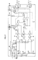
- the diagram of a circuit suitable for this is shown in FIG.
- FIG. 2 shows a constant current generator 10 with a voltage regulator 11 which is delimited by a dashed line and which drives an adjustable current through the temperature sensor 4. Depending on the temperature of the temperature sensor 4, its resistance and thus the falling voltage change.
- Pressing the button 9 opens the solenoid valve 5 and triggers the filling process.
- the cryogenic liquid now flows through the insulated line 7 into the cryocontainer 6.
- the resulting exhaust gas cools the temperature sensor 4 below room temperature.
- the comparator 12 then changes its output signal, which is processed in the non-inverting buffer 13 and the switching logic 14 shown by a broken line.
- the lamp 15 now lights up, which indicates the “self-holding” state. Now the button 9 can be released without interrupting the filling process.
- the comparator 16 changes its output signal. This causes the switching logic 14 to interrupt the filling process.
- a break in the line to the temperature sensor 4 causes the measuring voltage at the comparator 17 to rise to the level of the supply voltage.
- the comparator 17 registers this and interrupts the filling process by means of the switching logic 14.
- the comparator 16 changes its output signal and interrupts the filling process via the non-inverting buffer 18 and the switching logic 14.
- the display of the "self-holding" state by means of the comparator 12, on the other hand, is not absolutely necessary, but increases operational reliability.
- the comparator 17 fulfills the same purpose with the non-inverting buffer 19 and the switching logic 14.
- the resistors 20, 21, 22 and 23 are used to form the reference voltages for the comparators 12, 16 and 17.
- the relay 24 responds when the fill mode, the relay 25 when Fault operating state.
- the lamp 26 indicates the operational readiness, the lamp 27 indicates that the tank is being filled and the lamp 28 lights up in the event of faults.
- temperature sensors can be arranged at different heights in the cryocontainer if they are only to be partially filled up to a certain height. The relevant temperature sensor is then connected to the filling station. To fill a cryocontainer, it is now only necessary to connect it to the filling station and to trigger the filling process by pressing a button until the "self-holding" display lights up. The further filling takes place automatically and does not have to be monitored. All work can be carried out by trained personnel.
Landscapes
- Physics & Mathematics (AREA)
- Thermal Sciences (AREA)
- Fluid Mechanics (AREA)
- General Physics & Mathematics (AREA)
- Filling Or Discharging Of Gas Storage Vessels (AREA)
- Separation By Low-Temperature Treatments (AREA)
Applications Claiming Priority (2)
| Application Number | Priority Date | Filing Date | Title |
|---|---|---|---|
| DE3538181 | 1985-10-26 | ||
| DE19853538181 DE3538181A1 (de) | 1985-10-26 | 1985-10-26 | Vorrichtung zur automatischen begrenzung des fuellstandes kryogener fluessigkeiten |
Publications (2)
| Publication Number | Publication Date |
|---|---|
| EP0220618A2 true EP0220618A2 (fr) | 1987-05-06 |
| EP0220618A3 EP0220618A3 (fr) | 1989-02-08 |
Family
ID=6284573
Family Applications (1)
| Application Number | Title | Priority Date | Filing Date |
|---|---|---|---|
| EP86114336A Withdrawn EP0220618A3 (fr) | 1985-10-26 | 1986-10-16 | Dispositif de limitation automatique de niveau de fluides cryogéniques |
Country Status (2)
| Country | Link |
|---|---|
| EP (1) | EP0220618A3 (fr) |
| DE (1) | DE3538181A1 (fr) |
Cited By (4)
| Publication number | Priority date | Publication date | Assignee | Title |
|---|---|---|---|---|
| US6221349B1 (en) | 1998-10-20 | 2001-04-24 | Avigen, Inc. | Adeno-associated vectors for expression of factor VIII by target cells |
| EP1039271A3 (fr) * | 1999-03-19 | 2003-09-10 | Linde AG | Régulation de niveau de remplissage de liquides dans des réservoirs sous pression |
| US7351577B2 (en) | 1998-10-20 | 2008-04-01 | Genzyme Corporation | Adeno-associated vector compositions for expression of Factor VIII |
| NL2003849C2 (nl) * | 2009-11-23 | 2011-05-24 | Stichting Energie | Niveausensor in een verdamper. |
Family Cites Families (5)
| Publication number | Priority date | Publication date | Assignee | Title |
|---|---|---|---|---|
| DE1178616B (de) * | 1962-05-23 | 1964-09-24 | Siemens Elektrogeraete Gmbh | Elektrischer Zustandsgeber fuer das Niveau einer Fluessigkeit |
| DE3133421C2 (de) * | 1981-08-24 | 1985-10-24 | Vdo Adolf Schindling Ag, 6000 Frankfurt | Einrichtung zum elektrischen Überwachen des Niveaus einer in einem Behälter enthaltenen Flüssigkeit |
| DE3201708C2 (de) * | 1982-01-21 | 1986-07-31 | Kernforschungsanlage Jülich GmbH, 5170 Jülich | Meßfühler zur Bestimmung der Standhöhe von flüssigen Gasen |
| DE3223369C2 (de) * | 1982-06-23 | 1985-10-17 | A 2000 Industrie-Elektronik GmbH, 7632 Friesenheim | Verfahren und Überwachungsschaltung zur Funktionsprüfung des Kaltleiters einer Grenzwertgebersonde |
| DE3408824A1 (de) * | 1984-03-10 | 1985-09-12 | Vdo Adolf Schindling Ag, 6000 Frankfurt | Schaltungsanordnung zur elektrothermischen, umgebungstemperatur-kompensierten fuellstandsmessung |
-
1985
- 1985-10-26 DE DE19853538181 patent/DE3538181A1/de not_active Ceased
-
1986
- 1986-10-16 EP EP86114336A patent/EP0220618A3/fr not_active Withdrawn
Cited By (5)
| Publication number | Priority date | Publication date | Assignee | Title |
|---|---|---|---|---|
| US6221349B1 (en) | 1998-10-20 | 2001-04-24 | Avigen, Inc. | Adeno-associated vectors for expression of factor VIII by target cells |
| US7351577B2 (en) | 1998-10-20 | 2008-04-01 | Genzyme Corporation | Adeno-associated vector compositions for expression of Factor VIII |
| EP1039271A3 (fr) * | 1999-03-19 | 2003-09-10 | Linde AG | Régulation de niveau de remplissage de liquides dans des réservoirs sous pression |
| NL2003849C2 (nl) * | 2009-11-23 | 2011-05-24 | Stichting Energie | Niveausensor in een verdamper. |
| WO2011062498A1 (fr) * | 2009-11-23 | 2011-05-26 | Stichting Energieonderzoek Centrum Nederland | Capteur de niveau dans un évaporateur |
Also Published As
| Publication number | Publication date |
|---|---|
| DE3538181A1 (de) | 1987-04-30 |
| EP0220618A3 (fr) | 1989-02-08 |
Similar Documents
| Publication | Publication Date | Title |
|---|---|---|
| DE3836365A1 (de) | Befuelleinrichtung | |
| EP0220618A2 (fr) | Dispositif de limitation automatique de niveau de fluides cryogéniques | |
| DE3228265C2 (fr) | ||
| DE3723943A1 (de) | Einrichtung zur messung und ueberwachung der in einen tank ueber das tankfuellrohr einstroemenden fluessigkeitsmenge und der dadurch aus dem tank- be- und entlueftungsorgan ausstroemenden gas/dampfgemisch-menge | |
| EP0118073B1 (fr) | Procédé pour entourer des corps métalliques, en particulier enroulements de survoltage de transformateur | |
| DE1028886B (de) | Vorrichtung zur UEberwachung der Dichtheit von Kohlensaeureflaschen, insbesondere fuer Feuerloeschzwecke, und Schaltung fuer eine von dieser Vorrichtung zu betaetigende Alarmeinrichtung | |
| DE3019300A1 (de) | Vorrichtung zum befuellen von kraftstofftanks | |
| DE3727308A1 (de) | Fassfuellvorrichtung mit waage | |
| EP0117449B1 (fr) | Dispositif de commande pour le remplissage de liquides | |
| DE846303C (de) | Schwimmergesteuerte UEberwachungseinrichtung, insbesondere fuer Ausgleichsbehaelter von Heizungs- oder Kuehlanlagen | |
| CH402738A (de) | Flüssigkeitsbehälter, insbesondere Brennstofftank, mit Überwachungseinrichtung | |
| DE3013019A1 (de) | Verfahren zur ueberpruefung einer fluessigkeitsmangelanzeige und vorrichtung zur durchfuehrung des verfahrens | |
| DE709277C (de) | Verfahren zum Einpressen von unter Druck stehenden verfluessigten Gasen in Behaelter | |
| DE517364C (de) | Einrichtung zur Bestimmung und Registrierung der Dichte von gasfoermigen oder fluessigen Medien nach dem Bunsenschen Ausstroemungsprinzip | |
| DE549889C (de) | Vorrichtung zum staendigen Anzeigen des Fluessigkeitsstandes in Tanks oder anderen Behaeltern | |
| AT231187B (de) | Flüssigkeitsbehälter, insbesondere Brennstofftank, mit Überwachungseinrichtung | |
| DE885627C (de) | Anlage fuer Treibgasbetrieb von Verbrennungskraftmaschinen | |
| DE2307287C3 (de) | Vorrichtung zum Nachfüllen von flüssigen Gasen | |
| DE566204C (de) | Vorrichtung zum Sichtbarmachen des Fluessigkeitsstandes in Behaeltern von elektrischen Apparaten, insbesondere Transformatoren, mit hochliegendem Ausdehnungsgefaess | |
| DE885505C (de) | Anlage fuer Treibgasbetrieb von Verbrennungskraftmaschinen | |
| DE8216671U1 (de) | Abfuellsicherung | |
| CH393792A (de) | Verfahren und Einrichtung zum kontinuierlichen Messen und Anzeigen der Viscosität von Flüssigkeit | |
| DE29909879U1 (de) | Vorrichtung zum Prüfen der Ausgabe eines Schaltimpulses eines elektronischen Strömungswächters | |
| DE699536C (de) | Einrichtung zur Zeitkontrolle von in regelmaessige | |
| DE1263332B (de) | Anzeigevorrichtung fuer den Fluessigkeitsstand in einem Kraftstoffbehaelter, insbesondere von Kraftfahrzeugen |
Legal Events
| Date | Code | Title | Description |
|---|---|---|---|
| PUAI | Public reference made under article 153(3) epc to a published international application that has entered the european phase |
Free format text: ORIGINAL CODE: 0009012 |
|
| AK | Designated contracting states |
Kind code of ref document: A2 Designated state(s): FR GB NL |
|
| PUAL | Search report despatched |
Free format text: ORIGINAL CODE: 0009013 |
|
| AK | Designated contracting states |
Kind code of ref document: A3 Designated state(s): FR GB NL |
|
| STAA | Information on the status of an ep patent application or granted ep patent |
Free format text: STATUS: THE APPLICATION IS DEEMED TO BE WITHDRAWN |
|
| 18D | Application deemed to be withdrawn |
Effective date: 19890809 |
|
| RIN1 | Information on inventor provided before grant (corrected) |
Inventor name: HETTINGER, WOLFGANG |