EP0219785A2 - Dispositif pour le compactage de matériau et la réduction de sa teneur en liquide - Google Patents
Dispositif pour le compactage de matériau et la réduction de sa teneur en liquide Download PDFInfo
- Publication number
- EP0219785A2 EP0219785A2 EP86114132A EP86114132A EP0219785A2 EP 0219785 A2 EP0219785 A2 EP 0219785A2 EP 86114132 A EP86114132 A EP 86114132A EP 86114132 A EP86114132 A EP 86114132A EP 0219785 A2 EP0219785 A2 EP 0219785A2
- Authority
- EP
- European Patent Office
- Prior art keywords
- casing
- helice
- disposed
- discharge opening
- hose
- Prior art date
- Legal status (The legal status is an assumption and is not a legal conclusion. Google has not performed a legal analysis and makes no representation as to the accuracy of the status listed.)
- Withdrawn
Links
Images

Classifications
-
- B—PERFORMING OPERATIONS; TRANSPORTING
- B30—PRESSES
- B30B—PRESSES IN GENERAL
- B30B9/00—Presses specially adapted for particular purposes
- B30B9/02—Presses specially adapted for particular purposes for squeezing-out liquid from liquid-containing material, e.g. juice from fruits, oil from oil-containing material
- B30B9/12—Presses specially adapted for particular purposes for squeezing-out liquid from liquid-containing material, e.g. juice from fruits, oil from oil-containing material using pressing worms or screws co-operating with a permeable casing
- B30B9/121—Screw constructions
-
- B—PERFORMING OPERATIONS; TRANSPORTING
- B30—PRESSES
- B30B—PRESSES IN GENERAL
- B30B9/00—Presses specially adapted for particular purposes
- B30B9/02—Presses specially adapted for particular purposes for squeezing-out liquid from liquid-containing material, e.g. juice from fruits, oil from oil-containing material
- B30B9/12—Presses specially adapted for particular purposes for squeezing-out liquid from liquid-containing material, e.g. juice from fruits, oil from oil-containing material using pressing worms or screws co-operating with a permeable casing
- B30B9/18—Presses specially adapted for particular purposes for squeezing-out liquid from liquid-containing material, e.g. juice from fruits, oil from oil-containing material using pressing worms or screws co-operating with a permeable casing with means for adjusting the outlet for the solid
Definitions
- the present invention relates to an apparatus for compacting and reducing the liquid content of material mixtures which include, apart from liquid, rigid and elastic bodies of, for instance, different sizes, densities, elasticities, moisture content, etc., the apparatus including, first, at least one floating helice which, for conveying the material mixture, is rotated about its axis, the helice being disposed in a preferably enclosed casing, and, secondly, means cooperating with the helice which, during compaction of the material, further assist the reduction of the volume of the material and its liquid content.
- Material mixtures of the type mentioned by way of introduction, and hereinafter abbreviated to material need to be moved in many different contexts, for example in industrial operations, in municipal waste disposal etc. (slaugheter house offal, residual products in food production, refuse, screenings from the purification of wastewater etc.).
- Enormous quantities of material of the above-disclosed, or similar types are handled daily and it is a matter of fact that such material cannot be handled without considerable problems.
- These problems are a result of the fact that the material is, for example, bulky, contains a high proportion of liquid, is slippery, is tacky etc., and is consequently difficult to grasp firmly. Consequently, for rational handling, it is necessary to compact the material and reduce its liquid content.
- a considerable and seemingly intractible problem is also involved in removing residual material deposits from prior art plants for the operations contemplated above.
- the present invention relates to an apparatus for compacting and reducing the liquid content in material, and in particular for the compaction and reduction of material mixtures of the types disclosed above.
- the apparatus according to the present invention meets the above-outlined wishes and obviates the above-disclosed drawbacks inherent in currently applied prior art technology.
- use is made of a combination of a floating helice and a casing, which entails that the equipment is extremely compact, simple in its construction, operationally reliable, easy to clean and affords a steady and trouble-free conveyance and processing of the material.
- the apparatus may be made to operate continuously or intermittently, it nevertheless applying that the degree of functional reliability is just as high irrespective of the choice of operational mode. Neither will the immediate environments suffer from any effects, since the apparatus affords the possibility of rendering the casing substantially completely enclosed.
- the apparatus is employed for the batchwise discharge of the material which is compacted and whose liquid content has been reduced.
- the apparatus according to the present invention includes at least one floating helice which is disposed in a preferably enclosed casing, for example, U-shaped and/or circular cross-section.
- a prime mover for the rotation of the helice is disposed in association with that section of the casing where the material is fed into the combination of casing and helice, while in the other section of the casing, i.e. in association with the discharge portion of the casing, there is disposed a zone where the cross-section of the casing is such that the casing encloses the helice with slight play.
- the casing is provided with an end region which is enclosed in the circumferential direction and is located in the geometric extension of the helice, but from which the helice proper is absent. There will hereby be formed a region in which the material is arrested and is compacted in that the casing, in this region, performs the function of a counterpressure member which counteracts the conveyance of the material by the helice.
- an elongate body fixed to the helice and disposed substantially in the axial direction thereof, the body as a rule protruding out from the helice in a direction towards the discharge opening.
- the elongate body is substantially cylindrical.
- the elongate body is designed as a hollow body. As a rule, parts of this body are disposed in the central cavity of the helice in the region most proximal the free end of the helice.
- the hollow body is preferably provided with drainage apertures, for example designed as narrow conical slots which are, as a rule, disposed in the axial direction of the helice.
- the hollow body terminates with a wall whose purpose is to prevent material from being displaced into the cavity of the elongate body.
- the thickness of the material layer is reduced in the compaction region, at the same time as the abutment surface of the material layer against its surroundings (casing and elongate body, respectively) is increased. Consequently, the forcing-out of liquid from the material will be facilitated and the compacted material will attain a high TS content.
- the arresting function of the casing is supplemented, or at least to a certain degree is replaced, by special counterpressure members which, in cooperation with the casing, amplify or, to a certain extent, actually realise the arresting effect.
- the compaction is further amplified in that the helice is provided with reducing pitch. The helice is completely free, i.e. is not journalled in that end which is directed towards the discharge portion of the casing.
- the helice Since the helice has a certain degree of elasticity in the radial direction, it will abut against the casing during its rotation, unless material which is in the process of being conveyed during certain - generally brief - periods prevents such abutment. On the other hand, the helice is extremely stable in its axial direction and thereby retains substantially its original length even against the counterpressure which is generated from the material under compaction.
- a spring-biased counterpressure plate constitutes one form of the above-disclosed special counterpressure members.
- the plate is shown journalled in the upper bounding surface of the casing and/or in association with the discharge opening of the casing.
- the counterpressure plate is disposed in a receptacle chamber.
- the arresting effect of the casing on the material is amplified in that the inner cross-sectional area of the casing is reduced most proximal the discharge opening.
- the counterpressure member consists of a receptacle device shiftable in the axial direction of the casing, for example, in the form of a container, a hose etc.
- the material is moved into the receptacle device, the material displacing the receptacle device in the axial direction of the helice.
- the counterpressure member consists of a floating helice disposed in a casing, this casing having an infeed opening connected to the discharge opening of the issuing casing.
- the orientation of the casing which issues the material is such that its axis is directed towards the centre axis of the helice in the receiving combination of casing and helice.
- the discharge opening is, here, provided with a coupling member which connects to a coupling member disposed on the infeed opening, both of these coupling members being rotatably journalled in one another for simple adjustment of the relative orientation of the two casings. That end region where there is no helice proper is, in certain physical applications, very short and its length has been selected so as to ensure that the two helices do not come into contact with one another during their rotation.
- the diameter of the casing of the receiving combination is, together with the pitch, speed of rotation and/or radial extent of the helice vanes of the receiving combination of casing and helice, adapted so as to realise an arrest of the material travel before the material arrives at the discharge opening of the issuing casing. It is hereby possible to attain a substantially complete filling of the space in the receiving casing. This substantially complete filling is a prerequisite to be able to transport the material upwardly in a more or less vertical direction. Thus, according to the present invention, it is possible to cause the axis of the receiving combination to be directed, for example, horizontally, vertically or at any interjacent point.
- the casing is provided with drainage apertures, for example foramina- tions, longitudinal slots etc., which are preferably located in that region of the casing where compaction of the material takes place.
- orientation of the casing is advantageously selected such that the discharge portion of the casing is located higher than its infeed portion, whereby liquid squeezed out during the compaction operation is conveyed in a direction opposite to the direction of travel of the material and is drained out from the casing through the above-mentioned drainage apertures.
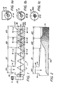
- FIG. 1-2 illustrate the present invention in one embodiment which shows the fundamental construction and function of the invention.
- an apparatus 1 which includes an elongate, fistular casing 2 in which is disposed a floating, shaftless helice 3. At its one end, the casing is provided with an infeed opening 14 which is connected to an upwardly directed drum 16.
- a motor 4 drives the helice 3.
- the other end of the casing constitutes the discharge portion 18 of the apparatus, this portion being provided with a discharge opening 24.
- the helice is solely journalled in conjunction with that end of the casing where the gearing and journalling unit is disposed, while the other end of the helice, which is directed towards the discharge portion, is completely free, which entails that, in this region, the helice does not rest in a bearing or journal of any kind, but, as a rule, abuts with its outer defining surface against the inner surface of the casing in a region which is restricted in the circumferential direction.
- An elongate body 100 is disposed in association with the end of the helice directed towards the discharge portion, the body being fixedly retained on the helice and being substantially disposed in the axial direction thereof.
- the body is substantially cylindrical.
- the combination of helice and casing is divided into an infeed zone 20, a precompaction zone 22 and a compaction zone 23.
- the apparatus according to the present invention is employed, not only for compaction, but also for conveyance of the material along the distance of travel required for such compaction.
- a conveyor zone 21 whose length is, naturally, determined by the desired travel distance.
- FIG. 1 also indicates by a solid line a relatively abrupt transition between the conveyor zone 21 and the pre-compaction zone 22.
- the embodiment illustrated by broken lines with a relatively continuous transition between the cross-sections of the conveyor zone and the pre-compaction zone is selected. In those physical applications where no specific conveyor zone is provided, the above-mentioned transitions are disposed between the infeed zone and the pre-compaction zone.
- Fig. 1 also shows how, in certain embodiments of the apparatus according to the present invention, the casing 2 is provided with drainage apertures 33.
- the drainage apertures are only provided in the lower portion of the path of travel, as regards the infeed zone 20 and conveyor zone 21 of the casing, but substantially throughout the circumference of the casing in its pre-compaction zone 22 and its compaction zone 23.
- Fig. 2 shows in particular how the material flow 40 occupies a relatively small portion of the cross-section of the casing as long as the material is located in the conveyor zone 21, and how the material, during its passage through the pre-compaction zone, occupies a steadily increasing proportion of the cross-section of the casing in order, as a rule, to substantially take up all of the available conveyor space in the compaction zone.
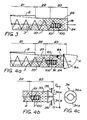
- Figs. 3-4 show how the combination of helice and casing is moreover provided with supplementary counterpressure members 25, 8 to further arrest the movement of the material in the compaction zone 23 of the casing. In certain physical applications, this arrest effect is amplified in that the inner cross-section of the casing is reduced in the region of the compaction zone 23, this feature being marked by broken lines in Fig. 3.
- Fig. 4a illustrates one embodiment in which the counterpressure member consists of a counterpressure plate 8a disposed in association with the discharge opening 24 and rotatably journalled at the upper region of the discharge opening and movable in the direction of the double-headed arrow A; and also an embodiment in which the counterpressure member consists of a counterpressure plate 8b which is rotatable and preferably return spring-biased in the upper bounding surface 27 of the casing 2.
- Fig. 4b is a partial longitudinal section
- Fig. 4c a view taken along the line D-D in Fig. 4b, of one embodiment in which the counterpressure member consists of a divisible cone 34.
- the cone consists of, for example, two halves 34a,b and is opened against the action of springs 35 whose spring force is adapted to provide that counter pressure which is required in order to attain the contemplated compaction of the material.
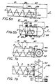
- the termination of the elongate body 100a,b, facing the infeed end consists of an end plate 104 provided with apertures 103, the end plate substantially preventing material from being moved into the cavity of the body.
- the size of the apertures is selected in view of the size of the bodies and particles included in the material.
- Figs. 8d,e show an embodiment of the drainage apertures 101 of the elongate body, these being shown as conical slots with their major opening area facing the centre axis of the elongate body.
- Figs. 8f-h show a preferred embodiment of that termination which the elongate body 100a turns to face towards the infeed end of the apparatus (counter to the material flow). This embodiment is particularly intended for use when minute bodies (particles) are borne in the material flow and may risk penetrating into the inner cavity of the elongate body.
- the elongate body is provided with a baffle plate 105 which is not provided with apertures and is located outside the end plate 104a.
- the baffle plate is connected to the elongate body, the connecting means holding the baffle plate fixed in spaced-apart relationship to the end plate such that there is formed a substantially columnar space 108 between the end plate and the baffle plate.
- the connecting means are designed such that the columnar space is exteriorly accessible through apertures 107 in the connecting means or therebetween.
- the inner cavity of the elongate body is hereby placed in communication with its ambient surroundings by means of the apertures 103 in the end plate 104a, the columnar space 108 and the apertures 107 in or between the connecting means 106.
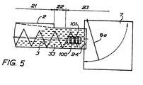
- the braking effect on the movement of the material in the compaction zone 23 by friction against the inner wall of the casing and against the elongate body 100 is supplemented by an additional braking effect by the action from the counterpressure plates 8a,b (Figs. 4, 5) or by reduction of the cross-sectional area of the casing (Fig. 3), or alternatively in that the casing is terminated by the cone 34 (Fig. 4b).
- the material is placed under pressure and the friction (braking effect) on the movement of the material is increased.
- hose - or alternatively hose in combination with container - is progressively forced out from the casing 2 by the action of forces from the material and against the counteraction of the forces designated F, whereby the material will retain the reduced volume occasioned by the earlier compaction, or, alternatively, be further compacted above and beyond the compaction previously attained.
- the conveyor apparatus 50 constitutes a counterpressure member in that the dimensions, pitch and speed of rotation of the casing 52 and the helice 53, respectively, have been selected such that the material is arrested on its passage out from the discharge opening 24 of the casing 2.
- the desired compaction of the material will be attained when the material is in the casing 52 of the receiving combination, and thereby requisite filling of the casing of the receiving combination.
- the above-described special (supplementary) counterpressure members are combined in certain embodiments, such that, for example, one and the same apparatus may include a counterpressure plate 8a,b and a terminating conical portion of the casing; a counterpressure plate 8a,b, and a shiftable receptacle device 26, 28; a cone 34 and a receiving casing 52 with its helice 53, and so on.
- arrest of the movement of the material in the compaction zone is effected to such a considerable extent that, at least in the area most proximal the discharge opening 24, the casing is as good as completely filled with material.
- the thus compacted material is thereafter caused to leave the casing through its discharge opening in batches whose size is determined by the rotation of the helice (that angular displacement which the helice undergoes) in conjunction with each discharge occasion.
- the elongate body 100 is disposed, in certain physical applications, to terminate a distance from the discharge opening of the casing, while, in other physical applications, terminating substantially flush with the discharge opening.
- This latter embodiment is particularly well-suited for the batchwise discharge of material as disclosed in the preceding paragraph, and in which the volume of material discharged on each individual discharge occasion is to be substantially of equal size.
- the casing 2 is disposed such that the material is moved slightly upwardly on its passage in a directior, towards the discharge opening 24. Drainage of the material will be hereby facilitated, since a portion of the liquid passes in a direction counter to the direction of movement of the material and, substantially in the centre of the floating helice, before the liquid runs out through the drainage apertures 33. The liquid will hereby be enabled to reach the drainage apertures of the casing in a region where the material has not yet been compacted to any appreciable degree.
- the mobility in a radial direction eliminates tendencies towards plug-formation, in that the helice is able to "clamber" against the wall of the casinc when material has accumulated on the bottom of the casing. As a result, the effect will be attained, during the continued rotation of the helice, that such material accumulations are progressively worn down and are moved towards the discharge opening of the apparatus.
Applications Claiming Priority (2)
| Application Number | Priority Date | Filing Date | Title |
|---|---|---|---|
| SE8504932A SE450104B (sv) | 1985-10-18 | 1985-10-18 | Anordning for komprimering av material och reduktion av dess vetskeinnehall |
| SE8504932 | 1985-10-18 |
Publications (2)
| Publication Number | Publication Date |
|---|---|
| EP0219785A2 true EP0219785A2 (fr) | 1987-04-29 |
| EP0219785A3 EP0219785A3 (fr) | 1988-12-14 |
Family
ID=20361853
Family Applications (1)
| Application Number | Title | Priority Date | Filing Date |
|---|---|---|---|
| EP86114132A Withdrawn EP0219785A3 (fr) | 1985-10-18 | 1986-10-13 | Dispositif pour le compactage de matériau et la réduction de sa teneur en liquide |
Country Status (5)
| Country | Link |
|---|---|
| US (1) | US4779528A (fr) |
| EP (1) | EP0219785A3 (fr) |
| CA (1) | CA1290186C (fr) |
| DE (1) | DE219785T1 (fr) |
| SE (1) | SE450104B (fr) |
Cited By (5)
| Publication number | Priority date | Publication date | Assignee | Title |
|---|---|---|---|---|
| DE3915528C1 (en) * | 1989-05-12 | 1990-12-13 | Noggerath & Co, 3061 Ahnsen, De | Screw conveyor with material moisture reduction - has spiral brush in grate region, matching pitch of conveyor screw |
| EP0565824A1 (fr) * | 1992-04-11 | 1993-10-20 | Voith Sulzer Stoffaufbereitung GmbH | Presse pour la déshydratation de matières par compression |
| EP0665053A2 (fr) * | 1993-12-29 | 1995-08-02 | General Electric Company | Appareil pour séparer des solides à partir de fluides |
| EP0820859A2 (fr) * | 1991-11-19 | 1998-01-28 | Spirac Engineering AB | Dispositif et procédé pour compacter des matériaux |
| EP1025984A1 (fr) * | 1999-02-01 | 2000-08-09 | Bormet Maschinenbau GmbH | Presse transporteuse |
Families Citing this family (43)
| Publication number | Priority date | Publication date | Assignee | Title |
|---|---|---|---|---|
| US5337658A (en) * | 1984-04-19 | 1994-08-16 | Spirac Engineering Ab | Conveying and compacting apparatus having a shaftless spiral in a casing with drainage openings |
| US5562029A (en) * | 1984-04-19 | 1996-10-08 | Spirac Engineering Ab | Conveying and compacting apparatus having a shaftless spiral in a casing with drainage openings |
| SE456149B (sv) * | 1987-02-18 | 1988-09-12 | Hedemora Ab | Forfarande och anordning for avvattning och pressning av material medelst en skruvpress |
| US5107852A (en) * | 1990-04-02 | 1992-04-28 | W. L. Gore & Associates, Inc. | Catheter guidewire device having a covering of fluoropolymer tape |
| US5013458A (en) * | 1990-04-06 | 1991-05-07 | Rdp Company | Process and apparatus for pathogen reduction in waste |
| US5186840A (en) * | 1991-08-26 | 1993-02-16 | Rdp Company | Process for treating sewage sludge |
| US5229011A (en) * | 1990-04-06 | 1993-07-20 | Christy Sr Robert W | Process for pathogen reduction in waste |
| US5405536A (en) * | 1990-04-06 | 1995-04-11 | Rdp Company | Process and apparatus for pathogen reduction in waste |
| US5421251A (en) * | 1991-11-19 | 1995-06-06 | Spirac Engineering Ab | Apparatus for compacting material |
| US5320861A (en) * | 1992-01-03 | 1994-06-14 | Ocean Spray Cranberries, Inc. | Fruit extraction and infusion |
| GB9220382D0 (en) * | 1992-09-26 | 1992-11-11 | Hamilton Robin | Compacting apparatus |
| DE4419612A1 (de) * | 1994-06-03 | 1995-12-07 | Noggerath Holding Gmbh Co Kg | Spiralförderer |
| AT409108B (de) * | 1996-04-25 | 2002-05-27 | Andritz Ag Maschf | Schneckenpresse zum abtrennen von flüssigkeiten aus feststoff-flüssigkeits-mischungen, insbesondere faserstoffsuspensionen |
| US6440483B1 (en) | 1999-12-28 | 2002-08-27 | Decas Cranberry Products, Inc. | Method and apparatus for producing a fruit product |
| FR2816222B1 (fr) * | 2000-11-03 | 2003-08-15 | Pari | Melangeur a balourd |
| DE20210004U1 (de) * | 2002-06-28 | 2003-11-20 | Cms Spa | Vorrichtung zum Verdichten von Material |
| CA2541737C (fr) * | 2003-10-15 | 2011-03-08 | Nordic Water Products Ab | Appareil et procede pour traiter des boues |
| US6871617B1 (en) | 2004-01-09 | 2005-03-29 | Ford Global Technologies, Llc | Method of correcting valve timing in engine having electromechanical valve actuation |
| US7032545B2 (en) * | 2004-03-19 | 2006-04-25 | Ford Global Technologies, Llc | Multi-stroke cylinder operation in an internal combustion engine |
| US7559309B2 (en) | 2004-03-19 | 2009-07-14 | Ford Global Technologies, Llc | Method to start electromechanical valves on an internal combustion engine |
| US7383820B2 (en) | 2004-03-19 | 2008-06-10 | Ford Global Technologies, Llc | Electromechanical valve timing during a start |
| US7055483B2 (en) * | 2004-03-19 | 2006-06-06 | Ford Global Technologies, Llc | Quick starting engine with electromechanical valves |
| US7028650B2 (en) * | 2004-03-19 | 2006-04-18 | Ford Global Technologies, Llc | Electromechanical valve operating conditions by control method |
| US7031821B2 (en) | 2004-03-19 | 2006-04-18 | Ford Global Technologies, Llc | Electromagnetic valve control in an internal combustion engine with an asymmetric exhaust system design |
| US7072758B2 (en) | 2004-03-19 | 2006-07-04 | Ford Global Technologies, Llc | Method of torque control for an engine with valves that may be deactivated |
| US7555896B2 (en) | 2004-03-19 | 2009-07-07 | Ford Global Technologies, Llc | Cylinder deactivation for an internal combustion engine |
| US7063062B2 (en) | 2004-03-19 | 2006-06-20 | Ford Global Technologies, Llc | Valve selection for an engine operating in a multi-stroke cylinder mode |
| US6938598B1 (en) | 2004-03-19 | 2005-09-06 | Ford Global Technologies, Llc | Starting an engine with electromechanical valves |
| US7194993B2 (en) | 2004-03-19 | 2007-03-27 | Ford Global Technologies, Llc | Starting an engine with valves that may be deactivated |
| US7240663B2 (en) | 2004-03-19 | 2007-07-10 | Ford Global Technologies, Llc | Internal combustion engine shut-down for engine having adjustable valves |
| US7140355B2 (en) | 2004-03-19 | 2006-11-28 | Ford Global Technologies, Llc | Valve control to reduce modal frequencies that may cause vibration |
| US7107947B2 (en) * | 2004-03-19 | 2006-09-19 | Ford Global Technologies, Llc | Multi-stroke cylinder operation in an internal combustion engine |
| US7032581B2 (en) | 2004-03-19 | 2006-04-25 | Ford Global Technologies, Llc | Engine air-fuel control for an engine with valves that may be deactivated |
| US7107946B2 (en) * | 2004-03-19 | 2006-09-19 | Ford Global Technologies, Llc | Electromechanically actuated valve control for an internal combustion engine |
| US7021289B2 (en) | 2004-03-19 | 2006-04-04 | Ford Global Technology, Llc | Reducing engine emissions on an engine with electromechanical valves |
| US7079935B2 (en) | 2004-03-19 | 2006-07-18 | Ford Global Technologies, Llc | Valve control for an engine with electromechanically actuated valves |
| US7128687B2 (en) | 2004-03-19 | 2006-10-31 | Ford Global Technologies, Llc | Electromechanically actuated valve control for an internal combustion engine |
| US7128043B2 (en) * | 2004-03-19 | 2006-10-31 | Ford Global Technologies, Llc | Electromechanically actuated valve control based on a vehicle electrical system |
| US7165391B2 (en) | 2004-03-19 | 2007-01-23 | Ford Global Technologies, Llc | Method to reduce engine emissions for an engine capable of multi-stroke operation and having a catalyst |
| US7017539B2 (en) * | 2004-03-19 | 2006-03-28 | Ford Global Technologies Llc | Engine breathing in an engine with mechanical and electromechanical valves |
| US7958820B2 (en) * | 2006-08-02 | 2011-06-14 | Duperon Innovation, Inc. | Compactor construction |
| US9963299B2 (en) | 2013-07-02 | 2018-05-08 | Kenneth Blanchard | Single flight screw, a single flight high pressure screw pump and compactor containing such a pump |
| US11680379B2 (en) | 2019-02-15 | 2023-06-20 | Douglas Dynamics, L.L.C. | Spreader with shaftless auger |
Citations (8)
| Publication number | Priority date | Publication date | Assignee | Title |
|---|---|---|---|---|
| DE1302893B (de) * | 1960-08-11 | The Bauer Bros. Co., Springfield, Ohio (V.St.A.) | Schneckenpresse für feuchte Massen | |
| GB928608A (en) * | 1959-11-16 | 1963-06-12 | Gustave Julin Et Fils | Improvements in continuous screw presses |
| GB1127889A (en) * | 1966-04-27 | 1968-09-18 | Dorr Oliver Inc | Feeding and dewatering apparatus |
| DE3002326A1 (de) * | 1979-01-23 | 1980-08-07 | Murat Vas Muratidis & Co A I S | Schneckenfoerderer |
| EP0037041A1 (fr) * | 1980-03-27 | 1981-10-07 | Stake Technology Ltd. | Presse pour l'extraction en continu de liquide d'une masse |
| FR2522585A1 (fr) * | 1982-03-02 | 1983-09-09 | Somavi | Pressoir a vis |
| EP0152724A1 (fr) * | 1982-08-18 | 1985-08-28 | COSTARELLI, Edoardo | Presse à vis, en particulier pour des matériaux plastiques, actionnée par un moteur électrique et un réducteur |
| WO1985004837A1 (fr) * | 1984-04-19 | 1985-11-07 | Spirac Engineering Ab | Appareil de transport |
Family Cites Families (10)
| Publication number | Priority date | Publication date | Assignee | Title |
|---|---|---|---|---|
| US2765899A (en) * | 1952-04-29 | 1956-10-09 | Wallace & Tiernan Inc | Dry feeder |
| US3062129A (en) * | 1960-08-16 | 1962-11-06 | Wandel Kurt | Material feeding unit |
| US3230902A (en) * | 1962-01-11 | 1966-01-25 | Constantflo Machinery Co Inc | Device for making blocks of vegetable, animal, or mineral matter |
| LU54716A1 (fr) * | 1967-10-23 | 1968-01-26 | ||
| US3760717A (en) * | 1970-08-18 | 1973-09-25 | Mil Pac Systems Inc | Shredder-compactor |
| US4256035A (en) * | 1979-01-02 | 1981-03-17 | Neufeldt Jacob J | Refuse compacting device |
| DE3043194A1 (de) * | 1980-11-15 | 1982-07-01 | Hermann Berstorff Maschinenbau Gmbh, 3000 Hannover | Einrichtung zum mechanischen trennen von fluessigkeiten aus fluessigkeitsfeststoffgemischen in einer schneckenpresse |
| DE3248059A1 (de) * | 1982-12-24 | 1984-07-05 | Hermann Berstorff Maschinenbau Gmbh, 3000 Hannover | Auspresseinrichtung |
| FR2543487B2 (fr) * | 1983-03-28 | 1985-09-27 | Pressoir a vis | |
| US4655128A (en) * | 1985-08-05 | 1987-04-07 | St Clair Rodney | Bulk material compressor |
-
1985
- 1985-10-18 SE SE8504932A patent/SE450104B/sv not_active IP Right Cessation
-
1986
- 1986-10-13 DE DE198686114132T patent/DE219785T1/de active Pending
- 1986-10-13 EP EP86114132A patent/EP0219785A3/fr not_active Withdrawn
- 1986-10-17 US US06/920,698 patent/US4779528A/en not_active Expired - Fee Related
- 1986-10-17 CA CA000520819A patent/CA1290186C/fr not_active Expired - Fee Related
Patent Citations (8)
| Publication number | Priority date | Publication date | Assignee | Title |
|---|---|---|---|---|
| GB928608A (en) * | 1959-11-16 | 1963-06-12 | Gustave Julin Et Fils | Improvements in continuous screw presses |
| DE1302893B (de) * | 1960-08-11 | The Bauer Bros. Co., Springfield, Ohio (V.St.A.) | Schneckenpresse für feuchte Massen | |
| GB1127889A (en) * | 1966-04-27 | 1968-09-18 | Dorr Oliver Inc | Feeding and dewatering apparatus |
| DE3002326A1 (de) * | 1979-01-23 | 1980-08-07 | Murat Vas Muratidis & Co A I S | Schneckenfoerderer |
| EP0037041A1 (fr) * | 1980-03-27 | 1981-10-07 | Stake Technology Ltd. | Presse pour l'extraction en continu de liquide d'une masse |
| FR2522585A1 (fr) * | 1982-03-02 | 1983-09-09 | Somavi | Pressoir a vis |
| EP0152724A1 (fr) * | 1982-08-18 | 1985-08-28 | COSTARELLI, Edoardo | Presse à vis, en particulier pour des matériaux plastiques, actionnée par un moteur électrique et un réducteur |
| WO1985004837A1 (fr) * | 1984-04-19 | 1985-11-07 | Spirac Engineering Ab | Appareil de transport |
Cited By (11)
| Publication number | Priority date | Publication date | Assignee | Title |
|---|---|---|---|---|
| DE3915528C1 (en) * | 1989-05-12 | 1990-12-13 | Noggerath & Co, 3061 Ahnsen, De | Screw conveyor with material moisture reduction - has spiral brush in grate region, matching pitch of conveyor screw |
| EP0820859A2 (fr) * | 1991-11-19 | 1998-01-28 | Spirac Engineering AB | Dispositif et procédé pour compacter des matériaux |
| EP0820859A3 (fr) * | 1991-11-19 | 1998-07-01 | Spirac Engineering AB | Dispositif et procédé pour compacter des matériaux |
| EP0565824A1 (fr) * | 1992-04-11 | 1993-10-20 | Voith Sulzer Stoffaufbereitung GmbH | Presse pour la déshydratation de matières par compression |
| EP0565823A1 (fr) * | 1992-04-11 | 1993-10-20 | Voith Sulzer Stoffaufbereitung GmbH | Presse pour la déshydratation de matières par compression |
| US5390592A (en) * | 1992-04-11 | 1995-02-21 | Sulzer Escher Wyss Gmbh | Dewatering press for compressibly dewaterable material |
| US5406883A (en) * | 1992-04-11 | 1995-04-18 | Sulzer Escher Wyss Gmbh | Dewatering press for compressibly dewaterable material |
| EP0665053A2 (fr) * | 1993-12-29 | 1995-08-02 | General Electric Company | Appareil pour séparer des solides à partir de fluides |
| EP0665053A3 (fr) * | 1993-12-29 | 1996-03-06 | Gen Electric | Appareil pour séparer des solides à partir de fluides. |
| EP1025984A1 (fr) * | 1999-02-01 | 2000-08-09 | Bormet Maschinenbau GmbH | Presse transporteuse |
| WO2000046019A1 (fr) * | 1999-02-01 | 2000-08-10 | Bormet Maschinenbau Gmbh | Presse a convoyeur |
Also Published As
| Publication number | Publication date |
|---|---|
| SE450104B (sv) | 1987-06-09 |
| US4779528A (en) | 1988-10-25 |
| DE219785T1 (de) | 1987-09-24 |
| SE8504932L (sv) | 1987-04-19 |
| CA1290186C (fr) | 1991-10-08 |
| SE8504932D0 (sv) | 1985-10-18 |
| EP0219785A3 (fr) | 1988-12-14 |
Similar Documents
| Publication | Publication Date | Title |
|---|---|---|
| EP0219785A2 (fr) | Dispositif pour le compactage de matériau et la réduction de sa teneur en liquide | |
| US7958820B2 (en) | Compactor construction | |
| WO2002007941A1 (fr) | Procede et dispositif de deshydratation et de pelletisation de combustible particulaire | |
| US5337658A (en) | Conveying and compacting apparatus having a shaftless spiral in a casing with drainage openings | |
| JPH0910522A (ja) | 固液分離装置 | |
| HU194088B (en) | Screw press for volume decreasing of materials | |
| EP0179842B1 (fr) | Appareil de transport | |
| US4397230A (en) | Screw press improvements | |
| US5562029A (en) | Conveying and compacting apparatus having a shaftless spiral in a casing with drainage openings | |
| US5406883A (en) | Dewatering press for compressibly dewaterable material | |
| US5421251A (en) | Apparatus for compacting material | |
| CN214646124U (zh) | 多级螺旋压榨机耐磨卸料装置 | |
| WO2019025077A1 (fr) | Revêtement pour un rotor d'une machine à fabriquer des comprimés et procédé d'évacuation de matière de comprimé excédentaire d'une chambre de compression d'une machine à fabriquer des comprimés | |
| EP0485909B1 (fr) | Dispositif pour compacter des récipients à petit volume pour liquides, spécialement des boîtes pour bière mal remplies ou des matériaux compactables similaires | |
| EP0105862A1 (fr) | Presse pour ordures | |
| DE2908842A1 (de) | Schneckenverdichter fuer rechengut | |
| KR19990069845A (ko) | 음식쓰레기 처리장치 | |
| EP0675798B1 (fr) | Appareil et procede pour compacter des materiaux | |
| GEP20002005B (en) | Device for fastening in the press the braid-like drainage element for separating liquid substances from solid material | |
| CA1288719C (fr) | Dispositif transporteur | |
| LU503049B1 (de) | Rückstandsvorbehandlungsvorrichtung zur Abwasserbehandlung | |
| CN215320836U (zh) | 一种垃圾固液分离装置 | |
| JPS6068198A (ja) | 泥状物等脱液処理装置 | |
| KR101609608B1 (ko) | 유기폐기물 탈수기 | |
| MD1057C2 (ro) | Dispozitiv de presare |
Legal Events
| Date | Code | Title | Description |
|---|---|---|---|
| PUAI | Public reference made under article 153(3) epc to a published international application that has entered the european phase |
Free format text: ORIGINAL CODE: 0009012 |
|
| AK | Designated contracting states |
Kind code of ref document: A2 Designated state(s): AT BE CH DE ES FR GB GR IT LI LU NL SE |
|
| TCNL | Nl: translation of patent claims filed | ||
| DET | De: translation of patent claims | ||
| PUAL | Search report despatched |
Free format text: ORIGINAL CODE: 0009013 |
|
| AK | Designated contracting states |
Kind code of ref document: A3 Designated state(s): AT BE CH DE ES FR GB GR IT LI LU NL SE |
|
| 17P | Request for examination filed |
Effective date: 19890419 |
|
| 17Q | First examination report despatched |
Effective date: 19900627 |
|
| STAA | Information on the status of an ep patent application or granted ep patent |
Free format text: STATUS: THE APPLICATION IS DEEMED TO BE WITHDRAWN |
|
| 18D | Application deemed to be withdrawn |
Effective date: 19910220 |
|
| RIN1 | Information on inventor provided before grant (corrected) |
Inventor name: BRUKE, RICHARD |