EP0213540A2 - Klimagerät - Google Patents
Klimagerät Download PDFInfo
- Publication number
- EP0213540A2 EP0213540A2 EP86111450A EP86111450A EP0213540A2 EP 0213540 A2 EP0213540 A2 EP 0213540A2 EP 86111450 A EP86111450 A EP 86111450A EP 86111450 A EP86111450 A EP 86111450A EP 0213540 A2 EP0213540 A2 EP 0213540A2
- Authority
- EP
- European Patent Office
- Prior art keywords
- temperature
- room
- defrosting
- heat exchanger
- refrigerant
- Prior art date
- Legal status (The legal status is an assumption and is not a legal conclusion. Google has not performed a legal analysis and makes no representation as to the accuracy of the status listed.)
- Granted
Links
Images


Classifications
-
- F—MECHANICAL ENGINEERING; LIGHTING; HEATING; WEAPONS; BLASTING
- F24—HEATING; RANGES; VENTILATING
- F24F—AIR-CONDITIONING; AIR-HUMIDIFICATION; VENTILATION; USE OF AIR CURRENTS FOR SCREENING
- F24F5/00—Air-conditioning systems or apparatus not covered by F24F1/00 or F24F3/00, e.g. using solar heat or combined with household units such as an oven or water heater
-
- F—MECHANICAL ENGINEERING; LIGHTING; HEATING; WEAPONS; BLASTING
- F25—REFRIGERATION OR COOLING; COMBINED HEATING AND REFRIGERATION SYSTEMS; HEAT PUMP SYSTEMS; MANUFACTURE OR STORAGE OF ICE; LIQUEFACTION SOLIDIFICATION OF GASES
- F25B—REFRIGERATION MACHINES, PLANTS OR SYSTEMS; COMBINED HEATING AND REFRIGERATION SYSTEMS; HEAT PUMP SYSTEMS
- F25B13/00—Compression machines, plants or systems, with reversible cycle
-
- F—MECHANICAL ENGINEERING; LIGHTING; HEATING; WEAPONS; BLASTING
- F25—REFRIGERATION OR COOLING; COMBINED HEATING AND REFRIGERATION SYSTEMS; HEAT PUMP SYSTEMS; MANUFACTURE OR STORAGE OF ICE; LIQUEFACTION SOLIDIFICATION OF GASES
- F25D—REFRIGERATORS; COLD ROOMS; ICE-BOXES; COOLING OR FREEZING APPARATUS NOT OTHERWISE PROVIDED FOR
- F25D21/00—Defrosting; Preventing frosting; Removing condensed or defrost water
- F25D21/002—Defroster control
Definitions
- the present invention relates to an air conditioning apparatus capable of removing frost in an outdoor side heat exchanger while room-warming operation is carried out.
- Figure 1 shows a conventional air conditioning apparatus.
- a reference numeral 1 designates a compressor
- a numeral 2 designates a four-way valve
- a numeral 3 designates a room side heat exchanger
- a numeral 4 designates a capillary tube for room-warming operation
- a numeral 5 designates an outdoor side heat exchanger
- a numeral 6 designates an accumulator
- a numeral 7 designates a capillary tube for cooling and defrosting operations
- numerals 8 and 9 designate check valves
- numerals 10 and 11 designate first and second temperature detectors respectively provided at the inlet and outlet sides of pipings connected to the outdoor side heat exchanger 5
- a numeral 12 designates a controlling device which is electrically connected to the first and second temperature detectors 10, 11; possesses the function of a timer, and outputs a signal to change operations from room-warming to defrosting and vice versa.
- a refrigerant discharged from the compressor 1 is passed through the four-way valve 2, the room side heat exchanger 3, the check valve 8, the capillary tube 4 for room-warming, the outdoor side heat exchanger 5 to be returned to the compressor 1 via the accumulator 6 after it has again been passed through the four-way valve 2.
- the refrigerant discharged from the compressor 1 flows through the four-way valve 2, the outdoor side heat exchanger 5, the check valve 9, the capillary tube 7 for defrosting (cooling), and the room side heat exchanger 3 to return to the compressor 1 via the four-way valve 2 and the accumulator 6; thus a cycle of circulation is formed.
- an integrating timer of the controlling device 12 counts time t, lapsed during the room-warming.
- the controlling device 12 compares the time t, with defrost prohibiting time t o ⁇ set in the controlling device 12 and compares the temperature T, of a piping which is detected by the first temperature detector 10 with a defrost initiating temperature T s .
- the controlling device outputs a signal to changing to the defrosting operation, while when t, > too and T, > T s , the room-warming operation is continued.
- the integrating timer counts time t2 lapsed in the defrosting operation, and the controlling device 12 compares the time t 2 with the longest defrosting time t Dmax set in the controlling device 12 and compares a temperature T of the piping which is detected by the second temperature detector 11 with a defrost ending temperature T E .
- the controlling device outputs a signal for changing to the room-warming operation.
- a timing changing from the room-warming operation to the defrosting operation is determined by the defrost prohibiting time, wherein the timing is usually fixed. Accordingly, the defrosting operation starts even when an amount of frost deposited in the outdoor side heat exchanger is small and the defrosting operation is unnecessary. On the contrary, even though a large amount of the frost remaines due to presence of the maximum defrosting time the room-warming operation is started.
- Figure 2 is the diagram of a controlling circuit in the defrosting operation of a conventional heatpump type air conditioning apparatus disclosed in, for instance, Japanese Unexamined Utility Model Publication 490393/1982.
- the same reference numerals as in Figure 1 designate the same or corresponding parts.
- the contact 13a or 13b in a changing switch 13 is operated.
- the contact 13a of the changing switch 13 is a normally closed contact.
- the contact 13a is opened and the contact 13b is closed.
- the contact 13a is connected to one side of the terminals 15 of a power source through a serial connection of the driving coil of the four-way valve 2 and one of switches 14 for room-warming operation.
- the contact 13b is connected to the one of the terminals 15 of the power source through a relay 16 and the other switch 14.
- the movable contact of the changing switch 13 is connected to the other terminal 15 of the power source. Between the terminals 15 of the power source, a serial connection of a normally closed contact 16a of the relay 16, a fan 17 for the room side heat exchanger 3 and a blowing rate regulating switch 18 is connected in parallel to the serial connection of the changing switch 13, relay 16 or the driving coil 2a and the switch 14.
- the switch 14 for the room-warming is closed to excite the driving coil 2a of the four-way valve whereby the four-way valve 2 is operated for the room-warming operation.
- a high temperature, high pressure gas discharged from the compressor 1 is supplied through the four-way valve 2 to the room side heat exchanger 3 where it is cooled by air forcibly fed by the fan 17.
- the refrigerant liquefied in the room side heat exchanger is supplied to a pressure reducing device 4 where it undergoes adiabatic expansion to become a low pressure refrigerant.
- the low pressure refrigerant evaporates in the outdoor side heat exchanger 5 by the heat of air forcibly blown by the fan for the outdoor side heat exchanger to become a low pressure gas.
- the low pressure gas is then sucked into the compressor 1 through the four-way valve 2.
- a calorie to be taken from the outdoor side heat exchanger 5 to the refrigerant circuit also decreases.
- deposition of frost starts in the outdoor side heat exchanger 5. The frost causes reduction in capability of taking up the heat in the refrigerant.
- the temperature of the pipe at the inlet side of the outdoor side heat exchanger 5 further decreases and it becomes a temperature lower than a predetermined temperature.
- the defrosting condition detector provided on the pipe near the inlet side of the heat exchanger 5 whereby the contact 13a of the changing switch 13 is opened. Accordingly, the driving coil 2a is deenergized to move the four-way valve 2 so that the refrigerant circuit is changed to cooling mode.
- the contact 13b is closed to excite the relay 16.
- the excitation of the relay 16 opens the normally closed contact 16a.
- the fan 17 for the room side heat exchanger is stopped so that cool air is not blown from the room side heat exchanger 3.
- any contact arm in the blowing rate regulating switch 18 is closed.
- the temperature of the temperature sensitive part of the defrosting condition detector 13 increases. Then, the contact 13a of the changing switch 13 is closed, while the contact 13b is opened, whereby the coil 2a of the four-way valve 2 is excited again and the four-way valve 2 is operated so that the operation is returned to room-warming mode.
- the room-warming operation was not carried out during the defrosting operation or for a certain time after the restarting of the room-warming operation. Accordingly, an occupant felt uncom- fortableness due to reduction in the room temperature.
- the present invention also provides an air conditioning apparatus comprising a refrigerant circuit in which a compressor, a four-way valve, a room side heat exchanger, a pressure-reducing device and an outdoor side heat exchanger are connected in this order, characterized by comprisses first check valve interposed between the discharge side of the compressor and the four-way valve, a refrigerant pipe line for connecting the discharge side of the compressor to the inlet side of the outdoor side heat exchanger in the case of room-warming operation, an electromagnetic valve disposed in the refrigerant pipe line and a defrosting condition detector for detecting a temperature for which a defrosting operation is started for said outdoor side heat exchanger, wherein the electromagnetic valve is opened by a signal from the defrosting condition detector, and a refrigerant path for feeding directly a part of a refrigerant from the compressor to the outdoor side heat exchanger, the refrigerant being returned to the compressor, is formed for a predetermined time.
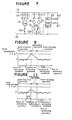
- Figure 3 shows the refrigerant circuit of a first embodiment of the present invention.
- the same reference numerals as in Figure 1 designate the same or corresponding parts.
- a reference numeral 1 designates a compressor
- a numeral 2 designates a four-way valve
- a numeral 3 designates a room side heat exchanger
- a numeral 4 designates a capillary tube for room-warming
- a numeral 5 designates an outdoor side heat exchanger
- a numeral 6 designates an accumulator
- a numeral 7 designates a capillary tube for cooling
- numerals 8 and 9 designate check valves
- a numeral 20 designates a temperature detector
- a numeral 21 designates a controlling device connected to the temperature detector 20.
- the controlling device has a timer for integrating time lapsed during the room-warming or the defrosting operation.
- the controlling device further determines a defrost prohibiting time t DS , a defrost initiating temperature T s and a defrost ending temperature T E , and outputs a signal to change operations from the defrosting to the room-warming and vice versa.
- Figure 4 shows the construction of the controlling device 21 in detail.
- Figure 4 is a diagram of the electric circuit of the controlling device 21 and parts related thereto.
- a reference numeral 21 designates the controlling device consisting of a micro-computer which includes an input circuit 23 and a CPU 24.
- the input circuit 23 receives signals from the temperature detector 20 and a room temperature detector 22 and outputs a signal to the CPU 24.
- the controlling device 21 is also provided with a timer 25 which passes and receives data to and from the CPU 24.
- the output of the CPU 24 is supplied to a relay coil 27 and a semiconductor relay 28 through an output circuit 26.
- the relay coil 27 has a contact 31.
- the contact 31 and an electromagnetic valve 30 is serially connected between the both polarities of a power source 33.
- the electromagnetic valve 30 is adapted to be excited or deenergized by opening and closing operations of the contact 31 depending on actuation and deenergization of the relay coil 27.
- a serial connection of the semiconductor relay 28 and a fan 29 for the room side heat exchanger is connected across the both polarities of the power source 33.
- the semiconductor relay 28 receives a signal from the output circuit 26, a conduction rate to the fan 29 is changed to thereby change the revolution of the fan 29.
- the primary coil of a transformer 32 is connected between the both polarities of the power source 33 to apply a voltage each part of the controlling device 21.
- T s represents a defrost initiating temperature
- T E represents a defrost ending temperature
- the temperature T, of the pipe line near the outdoor side heat exchanger 5 is detected by the temperature detector 20 provided on the pipe line connected to the outdoor side heat exchanger 5 at its inlet side during the room-warming operation (Step S3).
- Step 4 When the room-warming operation is established (Step 4), the time t, laped during the room-warming operation is integrated at Step S5 and the integrated time t, is compared with the initially set defrost prohibiting time Too at Step S6. On the other hand, the temperature T, of the pipe line is compared with the defrost initiating temperature T s at Step S7. When T, ⁇ t DS1 and T, 5 T s , a signal for changing to the defrosting operation is output, and at the same time, the time t, is cleared (Step S8). The room-warming operation is continued when the above-mentioned conditions do not establish.
- Step S9 when the defrosting operation is carried out (Step S9), the room temperature T S1 at the time of initiating defrosting operation is detected, and the defrosting timeAt D is integrated at Step S10. Then, the room temperature T s2 T a minutes after the initiation of the defrosting operation is detected at Step S11. The temperature T2 of the pipe line is detected at Step S12. The temperature T 2 of the pipe line is compared with the defrost ending temperature T E at Step S13. If T 2 ⁇ T E , the defrosting time ⁇ T D is compared with the maximum defrosting time T Dmax at Step S14.
- Step S17 When a room-warming changing signal is output, the defrosting time is cleared (Step S17).
- the defrosting operation is started at the optimum timing and unnecessary defrosting operation is prevented. Accordingly, the air conditioning apparatus can be operated at high efficiency, and comfortableness in a room can be obtained.
- the defrosting controlling device 36 generally comprises a micro-computer which includes a program ROM, a data RAM, an ALU (operating unit).
- the output terminal OUT1 of the defrosting controlling device 36 is adapted to change over the switching contact 13. Namely, the defrosting controlling device 36 reads the detecting signal input from the input terminals IN1, IN2 and sends the signal to the switching contact 13 from the output terminal OUT1 to perform the defrosting operation.
- Figure 8 is a flow chart showing the defrosting controlling device 36 actuated by the output signal of the defrosting condition detector 40
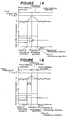
- Figure 9 is a diagram showing a relation between time and the room temperature during the defrosting operation.
- the increment of temperatureAT may be determined depending on a load in the room.
- the time AS may be determined in consideration that the capacity of room-warming is greately reduced by deposition of a large amount of frost in the outdoor side heat exchanger 5.
- the defrosting controlling device to let a set room temperature increase before initiation of the defrosting operation. Accordingly, reduction in the room temperature during the defrosting operation can be prevented and comfortableness in a living space can be obtained by a simple structure.
- the defrosting controlling device 36 consisting of a micro-computer is provided with input terminals IN1, IN2 and output terminals OUT1, OUT2 and includes a program ROM, a data RAM and ALU (operating unit).
- the input terminal IN1 receives a detecting signal from the defrosting condition detector 40.
- the input terminal IN2 receives a detecting signal from the room temperature detector 37 which senses a room temperature in a room.
- the defrosting controlling device 36 reads the detecting signals received in the input terminals IN1, IN2 and outputs from the output terminals OUT1 an output signal so that the changing switch 13 is operated to start the defrosting operation.
- the controlling device 36 also outputs from the output terminal OUT2 an output signal to the waveform regulating part 38.
- the waveform regulating part 38 is connected between the terminals 15 for the power source and controls the revolution of the compressor 1 de- peding on the output signal from the output terminal OUT2.
- the waveform regulating part 38 generally constitutes a device for driving an induction motor.
- Step S9 is taken to return the room-warming operation.
- the revolution of the compressor 1 is determined to be F3 ( Figure 14) which can be arbitrarity determined in the room-warming operation, and then, instruction is given to the room temperature detector 37 to have the originally set room temperature T; thus the condition is returned to the original room-warming operation (Step S11).
- the revolution of the compressor 1 is increased to (F1 + AF) just before the initiation of the defrosting operation and the room temperature is increased to (T +AT).
- the same effect can be obtained by starting the defrosting operation after the lapse of a certain time AS as shown in Figure 16 showing a relation between the room temperature and time.
- the defrosting operation is started after the time AS has lapsed during which the revolution of the compressor 1 and the room temperature has been increased.
- Fugures 17, 18 and 19 show a fourth embodiment of the present invention.
- the same reference numerals as in Figure 1, Figure 7 and Figure 12 designate the same or corresponding parts.
- Figure 17 is a diagram of the fourth embodi- merit.
- the fourth embodiment is so constructed that the defrosting condition detector 40 and the room temperature detector 37 are provided; when an output of the defrosting condition detector 40 is input to a set temperature increasing means 48, it lets a set temperature in the room temperature detector 37 increase; when a defrosting operation means 49 detects that the room temperature to be
- FIGS. 18 and 19 are respectively a circuit diagram and a block diagram of the defrosting controlling device according to the fourth embodiment of the present invention.
- a reference numeral 51 designates a defrosting controlling device comprising a micro-computer and includes a CPU 51A, a memory 51 B, an input circuit 51 C and an output circuit 51 D.
- the defrosting condition detector 40 is connected to an input terminal 11
- the room temperature detector 37 is connected to another input terminal 12 of the input circuit 51C
- the changing switch 13 is connected to an output terminal 01 of the output circuit 51 D.
- Step S1 the room-warming operation is performed at Step S1.
- Step S3 is taken so that a set temperature is determined to be (T + ⁇ T1) for starting of the defrosting operation, while the room-warming operation is continued.
- the temperature AT1 is determined by a value of reduction in the room temperature which has been detected by the room temperature dectector 37 in the previous defrosting operation. AT1 is zero before initiation of the first defrosting operation when the air conditioning apparatus has been started.
- the defrosting operation means 49 operates the changing switch 13 (Step 5) to start the defrosting operation.
- Step S8 the value ⁇ T2 is memorized as a value of an increment of the room temperature which is used for the next defrosting operation. Thereafter, the room-warming operation is restarted at Step S9.
- Step S10 the originally set temperature T is used and the original room-warming operation is carried out.
- Figure 21 is a diagram showing a relation between the room temperature and time in which the defrosting operations are repeatedly performed. Namely, a component AT a which is an amount of reduction of the room temperature in the previous defrosting operation is added to the next defrosting operation, and a component ⁇ Tb which is an amount of reduction in the room temperature in the instant defrosting operation is added to the further next defrosting operation. Accordingly, the room temperature just after the completion of a certain defrosting operation becomes almost near the original room temperature T. Thus, temperature is detected for each defrosting operation and a reduced temperature is used for the subsequent defrosting operation depending on a load in a room.
- Figures 22 and 23 are respectively a flow chart and a diagram showing a relation between room temperature and time in a modified form of the above-mentioned fourth embodiment.
- the modified embodiment is controlled such that an upper limit ofAT1 is provided.
- determination is made whether or not the increment of the room temperature A T1 is larger than a component ⁇ Tx of the upper limit of the room temperature at Step S11. If it is smaller than the upper limit temperature, then Step S3 is taken. On the other hand, if it is larger than the limit, a component of increased room temperature ⁇ T1 is changed to ⁇ Tx for the next defrosting operation at Step S12. ⁇ Tx is determined to be lower than the maximum room temperature of an air conditioning apparatus.
- the structure of the apparatus is made simple, while excessive reduction in the room temperature during the defrosting operation is prevented and a living space is kept in a comfortable condition.
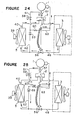
- Figures 24 and 25 show a fifth embodiment of the present invention.
- reduction in the room temperature during the defrosting operation can be prevented and noise generated from the four-way valve when it is operated can be eliminated.
- Figure 24 is a diagram of the refrigerant circuit in the room-warming operation, and Figure 25 is in the defrosting operation.
- a reference numeral 1 designates a compressor, a numeral 2 a four-way valve, a numeral 3 a room side heat exchanger, a numeral 5 an outdoor side heat exchanger, a numeral 46 a pipe line for a refrigerant, a numeral 17 a fan for the room side heat exchanger, a numeral 39 a fan for the outdoor side heat exchanger and a numeral 40 a defrosting condition detector.
- a mechanical type expansion valve 56 is placed in the pipe line 46 between the room side heat exchanger 3 and the outdoor side heat exchanger 5.
- a first check valve 57 is interposed between the outlet side of the compressor 1 and the four-way valve 2.
- a numeral 58 designates an electromagnetic valve, a numeral 59 a second check valve and a numeral 60 a capillary tube.
- a first by-pass line 61 is connected at its one end to the refrigerant pipe between the outlet side of the compressor 1 and the first check valve 57, and the other end of the first by-pass line is connected to the second check valve 59.
- a second by-pass line 62 extends between the second check valve 59 and the refrigerant pipe 46 between the outdoor side heat exchanger and the mechanical type expansion valve 56.
- a third by-pass line 63 extends between the first by-pass line 61 between the electromagnetic valve 58 and the second check valve 59 and the refrigerant pipe 46 between the compressor 1 and the four-way valve 2.
- the first by-pass line 61 includes the electromagnetic valve 58
- the third by-pass line 63 includes the capillary tube 60.
- a high temperature, high pressure refrigerant gas compressed in the compressor 1 is supplied through the first check valve 57 and the four-way valve 2 to the room side heat exchanger 3 where it is condensed while a room is warmed.
- the refrigerant liquid is then flown to the mechanical type expansion valve 56.
- the refrigerant is subjected to pressure-reduction in the expansion valve 56 and evaporates in the outdoor side heat exchanger 5.
- the refrigerant gas is then returned to the compressor 1 through the four-way valve 2. In this case, the refrigerant is not flown into the second and third by-pass lines 62, 63, since the electromagnetic valve 58 in the first by-pass line 61 is closed.
- the evaporation temperature for the refrigerant in the outdoor side heat exchanger 5 decreases to become a dew point temperature or lower, whereby deposition of frost in the outdoor side heat exchanger 5 begins. Accordingly, the temperature of the outdoor side heat changer 5 decreases.
- the defrosting condition detector 40 detects the diposition of frost, and the defrosting operation is started.
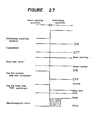
- Figure 27 shows a state of operation which is changed from the room-warming operation to the defrosting operation.
- Figure 25 shows the refrigerant circuit in the defrosting operation.
- the fan 39 for the outdoor side heat exchanger is stopped while the compressor 1 is continuously driven.
- the revolution of the fan 17 for the room side heat exchanger is lowered.
- the electromagnetic valve 58 undergoes repeated opening and closing operations for a predetermined time and a fixed intervals, after which the valve is opened.
- the operation of the electromagnetic valve 58 relieves a sudden change of pressure when operations is switched from the room-warming operation to the defrosting operation, and allows the high temperature, high pressure refrigerant gas compressed in the compressor 1 to send the second and third by-pass lines 62, 63 through the first by-pass line 61.
- the refrigerant forwarded in the second by-pass line 62 is directly supplied through the second check valve 59 to the outdoor side heat exchanger 5 to dissolve the frost while the refrigerant itself is condensed.
- the condesed refrigerant is mixed with the high temperature, high pressure refrigerant gas which is forwarded in the third by-pass line 63 through the capillary pipe 60.
- the refrigerant becomes a saturated gas at the down stream of the four-way valve 2, and finally it sucked into the compressor 1.
- the expansion valve 56 is closed. Accordingly, in the refrigerant circuit extending from the check valve 57 through the room side heat exchanger 3 to the expansion valve 56, a high pressure condition in the room-warming operation is maintained. Accordingly, warm air can be supplied in the room even in the defrosting operation, by sending a gentle stream of air by the fan 17 for the room side heat exchanger 3.
- modification may be made in such a manner that a current limiting valve 64 is provided in the first by-pass line 61 instead of the electromagnetic valve 58.
- Figure 28 is a time chart for the modified embodiment in which the current limiting valve 64 is provided.
- the valve body of the current limiting valve 64 is gradually opened whereby the high temperature, high pressure refrigerant gas compressed in the compressor 1 is supplied to the second and third by-pass lines 62, 63 through the first by-pass line 61.
- the same effect as the fifth embodiment can be obtained.
- the defrosting operation can be performed for a short time and a cool refrigerant is not forwarded in the room side heat exchanger, whereby the room-warming operation can be restarted quickly after the completion of the defrosting operation. Further, a living space in the room can be kept in comfortable condition.
- Figures 29 to 34 show the sixth embodiment of the present invention in which the same reference numerals designate the same or corresponding parts.
- Figure 29 is a diagram showing the refrigerant circuit of the sixth embodiment.
- a numeral 57 designates a check valve inserted between the outlet side of the compressor 1 and a four-way valve 2;
- a numeral 67 designates an electric type expansion valve in which the valve body - (not shown) is controlled between the entirely closed condition and the entirely opened condition by receiving an input signal
- a numeral 68 designates an electromagnetic valve connected between the outlet side of the compressor 1 and the inlet side of the outdoor side heat exchanger 5 in the room warming operation, and
- a numeral 69 designates a pipe temperature detector which is provided at a pipe line near the outdoor side heat exchanger 3 to detect its temperature.
- fans 17 and 39 as shown in Figure 24 are omitted.
- Figure 30 is a block diagram showing the entire construction of the defrosting controlling device.
- the device comprises the defrosting condition detector 40, an electromagnetic valve operating means 71 which receives an output from the defrosting condition detector 40 and outputs a signal to the electromagnetic valve 68 to control the same, an expansion valve controlling means 72 receives the output of the defrosting condition detector 40 and the output of the pipe temperature detector 69 and outputs a signal to the electric type expansion valve to control the degree of opening of the expansion valve 67.
- Figures 31 and 32 are respectively an electric circuit of an important part of the air conditioning apparatus of the sixth embodiment and a block diagram of a defrosting controlling device.
- a reference numeral 73 designates an defrosting controlling device comprising a micro-computer and includes a CPU 73A, a memory 73B, an input circuit 73C and an output circuit 73D.
- the defrosting condition detector 40 is connected to an input terminal 11 of the input circuit 73C, and the pipe temperature detector 69 is connected to another input terminal 12.
- a driving device (not shown) for a contact 74 of the electromagnetic valve 68 is connected to the output terminal 01 of the output circuit 73D, and electric type expansion valve 67 is connected to output terminals 02, 03.
- Figure 33 is a flow chart showing an operating program stored in the memory 73B in the defrosting controlling device 73
- Figure 34 is a diagram showing the operation of the electric type expansion valve 67.
- Step S1 the defrosting condition detector 40 observes whether the temperature at the outdoor side heat exchanger satisfies the defrosting condition (Step S2).
- Step S3 is taken to generate an output from the output terminal 01 of the defrosting controlling device 73 to thereby open the electromagnetic valve 68 by making the contact 74.
- an output is generated from the output terminal 03 at Step 4.
- the magnitude of the output is variable and the electromagnetic expansion valve 67 is driven so that the valve body is forced to be opened depending on the magnitude of the output as shown in Figure 34.
- Opening of the electromagnetic valve 68 permits the high temperature refrigerant gas produced in the compressor 1 to enter into the outdoor side heat exchanger 5 through the electromagnetic valve 68 so as to dissolve the frost deposited in the heat exchanger.
- the expansion valve 67 is entirely opened, and the high temperature refrigerant stayed in the room side heat exchanger 3 when the room-warming operation has been carried out is supplied into the outdoor side heat exchanger 5.
- the refrigerant from the room side heat exchanger 3 shortens a defrosting time.
- Step S5 determination is made by the pipe temperature detector 69 as to whether or not the temperature of the room side heat exchanger 3 is lower than a temperature T which gives cool feeling to the occupant (Step S5).
- Step S6 When the temperature of the room side heat exchanger 3 is lower than the temperature T, an output signal is generated from the output terminal 02 of the controlling device 73 (Step S6).
- the output signal drives the electric type expansion valve 6 in the direction closing the valve body depending on the magnitude of the output as shown in Figure 34. As a result, an amount of the refrigerant flowing from the room side heat exchanger 3 is decreased and the temperature of the room side heat exchanger 3 is increased whereby the feeling of warm is increased.
- Step S7 is taken to open the expansion valve 67 thereby shortening the defrosting time.
- Step S8 determination as to whether or not the defrosting condition is released is made at Step S8.
- the electromagnetic valve 68 is closed (Step S9) and thereafter the room-warming operation is restarted (Step S10).
- the temperature T is a critical temperature at which an occupant feels temperature reduction in the warming operation and corresponds to the temperature of blown air in the room-warming operation.
- the temperature T may be determined optionally.
- Figure 35 is a flow chart of a modified form of the sixth embodiment.
- the electric type expansion valve 67 is entirely opened for a predetermined time and thereafter it is entirely closed in contrast with the embodiment shown in Figure 33 in which the degree of opening of the valve body of the expansion valve 67 is controlled depending on the output of the pipe temperature detector 69 during the defrosting operation.
- the electric type expansion valve 67 is entirely opened.
- time A S is counted.
- the expansion valve 67 is entirely closed at Step S12.
- the process in Figure 35 is the same as those in Figure 33 except for the above-mentioned.
- the timeAS may be detemined by a time for which the occupant feels shortage of warming from the temperature of the room side heat exchanger 3 after the expansion valve 67 has been entirely opened.
- the modified embodiment provides the same function as the sixth embodiment. Further, it is unnecessary to use the pipe temperature detector 69, which simplifies the air conditioning apparatus.
Landscapes
- Engineering & Computer Science (AREA)
- Mechanical Engineering (AREA)
- General Engineering & Computer Science (AREA)
- Physics & Mathematics (AREA)
- Thermal Sciences (AREA)
- Chemical & Material Sciences (AREA)
- Combustion & Propulsion (AREA)
- Life Sciences & Earth Sciences (AREA)
- Sustainable Development (AREA)
- Air Conditioning Control Device (AREA)
Applications Claiming Priority (12)
| Application Number | Priority Date | Filing Date | Title |
|---|---|---|---|
| JP184905/85 | 1985-08-22 | ||
| JP60184905A JPS6246152A (ja) | 1985-08-22 | 1985-08-22 | 空気調和機 |
| JP184901/85 | 1985-08-22 | ||
| JP184904/85 | 1985-08-22 | ||
| JP60184901A JPS62116843A (ja) | 1985-08-22 | 1985-08-22 | 空気調和装置 |
| JP60184904A JPS6246151A (ja) | 1985-08-22 | 1985-08-22 | 空気調和機 |
| JP60229074A JPS6291759A (ja) | 1985-10-15 | 1985-10-15 | ヒートポンプ用冷凍サイクルの除霜方法 |
| JP229074/85 | 1985-10-15 | ||
| JP267825/85 | 1985-11-28 | ||
| JP60267826A JPH0621726B2 (ja) | 1985-11-28 | 1985-11-28 | 空気調和機 |
| JP267826/85 | 1985-11-28 | ||
| JP60267825A JPS62129638A (ja) | 1985-11-28 | 1985-11-28 | 空気調和機 |
Publications (3)
| Publication Number | Publication Date |
|---|---|
| EP0213540A2 true EP0213540A2 (de) | 1987-03-11 |
| EP0213540A3 EP0213540A3 (en) | 1990-05-23 |
| EP0213540B1 EP0213540B1 (de) | 1992-07-01 |
Family
ID=27553564
Family Applications (1)
| Application Number | Title | Priority Date | Filing Date |
|---|---|---|---|
| EP86111450A Expired - Lifetime EP0213540B1 (de) | 1985-08-22 | 1986-08-19 | Klimagerät |
Country Status (7)
| Country | Link |
|---|---|
| US (1) | US4709554A (de) |
| EP (1) | EP0213540B1 (de) |
| KR (1) | KR900005979B1 (de) |
| CN (2) | CN1005210B (de) |
| AU (1) | AU580509B2 (de) |
| DE (1) | DE3685862T2 (de) |
| HK (1) | HK15093A (de) |
Cited By (2)
| Publication number | Priority date | Publication date | Assignee | Title |
|---|---|---|---|---|
| EP0330230A1 (de) * | 1988-02-26 | 1989-08-30 | Sanden Corporation | Abtauverfahren eines Kältemittelkreislaufs zur Anwendung in einem Kühlwagen |
| EP0462679A1 (de) * | 1990-06-21 | 1991-12-27 | S.S.P. Lichtenvoorde B.V. | Verfahren und Vorrichtung zur Herstellung von Eis |
Families Citing this family (28)
| Publication number | Priority date | Publication date | Assignee | Title |
|---|---|---|---|---|
| JPH079331B2 (ja) * | 1986-12-26 | 1995-02-01 | 松下電器産業株式会社 | ヒートポンプ式空気調和機の運転制御方法 |
| US5131240A (en) * | 1988-12-23 | 1992-07-21 | Mitsubishi Denki Kabushiki Kaisha | Air conditioning apparatus |
| JPH0452441A (ja) * | 1990-06-18 | 1992-02-20 | Sanyo Electric Co Ltd | ヒートポンプ式空気調和機の着霜検知方式 |
| JP3495858B2 (ja) * | 1996-10-31 | 2004-02-09 | 東芝キヤリア株式会社 | 空気調和機 |
| US6237357B1 (en) * | 1999-06-07 | 2001-05-29 | Mitsubishi Heavy Industries, Ltd. | Vehicular air conditioner using heat pump |
| WO2003071193A2 (de) * | 2002-02-22 | 2003-08-28 | Karl Heinz Gast | Heizungssystem, verfahren zum betreiben eines heizungssystems und verwendung |
| CN100447508C (zh) * | 2004-06-03 | 2008-12-31 | 广东科龙电器股份有限公司 | 风冷冰箱的冷凝蒸发一体式除霜系统 |
| US8567689B2 (en) * | 2004-09-17 | 2013-10-29 | Carrier Corporation | Sanitary operator of a hot water heat pump |
| JP3786133B1 (ja) * | 2005-03-03 | 2006-06-14 | ダイキン工業株式会社 | 空気調和装置 |
| CN101187517B (zh) * | 2006-11-17 | 2010-05-12 | 海尔集团公司 | 空调除霜方法 |
| JP2009210161A (ja) * | 2008-02-29 | 2009-09-17 | Sanyo Electric Co Ltd | 機器制御システム、制御装置及び制御プログラム |
| WO2012077166A1 (ja) * | 2010-12-09 | 2012-06-14 | 三菱電機株式会社 | 空気調和装置 |
| US10747243B2 (en) * | 2011-12-14 | 2020-08-18 | Ademco Inc. | HVAC controller with HVAC system failure detection |
| CN104246382B (zh) * | 2012-03-14 | 2017-03-08 | 大金工业株式会社 | 调湿装置 |
| CN103353196A (zh) * | 2013-07-02 | 2013-10-16 | 天津大学 | 一种利用冷凝热的过冷水制冰装置除冰堵系统 |
| CN104864494B (zh) * | 2014-02-21 | 2018-11-09 | 大金工业株式会社 | 空调机室内机 |
| JP6466682B2 (ja) * | 2014-10-15 | 2019-02-06 | シャープ株式会社 | 空気調和機 |
| CN106918105A (zh) * | 2017-04-27 | 2017-07-04 | 广东美的制冷设备有限公司 | 空调系统 |
| CN110617643B (zh) * | 2018-07-08 | 2020-08-25 | 张宸浩 | 一种自除霜型的节能环保空调机组 |
| CN111623568A (zh) * | 2020-04-28 | 2020-09-04 | 珠海格力电器股份有限公司 | 一种制冷机组及其控制方法 |
| CN111692683A (zh) * | 2020-06-15 | 2020-09-22 | 云能科技有限公司 | 一种空气源热泵系统及其除霜、消毒方法 |
| CN114076400B (zh) * | 2020-08-21 | 2023-09-01 | 广东美的制冷设备有限公司 | 空调器的电子膨胀阀控制方法、设备、存储介质及装置 |
| CN112066610A (zh) * | 2020-10-10 | 2020-12-11 | 昆山台佳机电有限公司 | 一种空气源热泵机组的融霜控制系统 |
| CN112817267A (zh) * | 2020-12-28 | 2021-05-18 | 杭州新新制冷设备有限公司 | 一种尸体杀菌解冻机控制系统 |
| CN113465125B (zh) * | 2021-06-17 | 2023-05-26 | 青岛海尔空调电子有限公司 | 空调器的除霜控制方法、计算机可读存储介质及控制装置 |
| CN116398982A (zh) * | 2023-04-14 | 2023-07-07 | 青岛海尔空调器有限总公司 | 制冷系统、制冷系统的控制方法和空调 |
| CN116772287B (zh) * | 2023-05-16 | 2025-08-26 | 海信(广东)空调有限公司 | 一种空调器及空调器的除霜控制方法 |
| CN118856664B (zh) * | 2024-07-08 | 2025-11-25 | 中山市爱美泰电器有限公司 | 一种热泵装置及其控制方法 |
Family Cites Families (8)
| Publication number | Priority date | Publication date | Assignee | Title |
|---|---|---|---|---|
| US4406133A (en) * | 1980-02-21 | 1983-09-27 | The Trane Company | Control and method for defrosting a heat pump outdoor heat exchanger |
| JPS5749093A (en) * | 1980-09-08 | 1982-03-20 | Hitachi Ltd | Electric fan |
| US4356962A (en) * | 1980-11-14 | 1982-11-02 | Levine Michael R | Thermostat with adaptive operating cycle |
| JPS58115235A (ja) * | 1981-12-29 | 1983-07-08 | Sharp Corp | 空気調和機の制御回路 |
| JPS6069445A (ja) * | 1983-09-26 | 1985-04-20 | Toshiba Corp | 空気調和機 |
| JPS6082735A (ja) * | 1983-10-12 | 1985-05-10 | Toshiba Corp | ヒ−トポンプ式空気調和機 |
| JPS60144548A (ja) * | 1983-12-29 | 1985-07-30 | Matsushita Electric Ind Co Ltd | 空気調和機の除霜運転制御装置 |
| US4627245A (en) * | 1985-02-08 | 1986-12-09 | Honeywell Inc. | De-icing thermostat for air conditioners |
-
1986
- 1986-07-30 KR KR1019860006265A patent/KR900005979B1/ko not_active Expired
- 1986-08-19 EP EP86111450A patent/EP0213540B1/de not_active Expired - Lifetime
- 1986-08-19 DE DE8686111450T patent/DE3685862T2/de not_active Expired - Lifetime
- 1986-08-21 US US06/898,492 patent/US4709554A/en not_active Expired - Lifetime
- 1986-08-22 AU AU61785/86A patent/AU580509B2/en not_active Expired
- 1986-08-22 CN CN86105455.5A patent/CN1005210B/zh not_active Expired
-
1988
- 1988-09-07 CN CN88106586A patent/CN1008131B/zh not_active Expired
-
1993
- 1993-02-25 HK HK150/93A patent/HK15093A/en not_active IP Right Cessation
Cited By (4)
| Publication number | Priority date | Publication date | Assignee | Title |
|---|---|---|---|---|
| EP0330230A1 (de) * | 1988-02-26 | 1989-08-30 | Sanden Corporation | Abtauverfahren eines Kältemittelkreislaufs zur Anwendung in einem Kühlwagen |
| US4944158A (en) * | 1988-02-26 | 1990-07-31 | Sanden Corporation | Method of defrosting a refrigerating circuit for use in cooling a vehicular chamber |
| EP0462679A1 (de) * | 1990-06-21 | 1991-12-27 | S.S.P. Lichtenvoorde B.V. | Verfahren und Vorrichtung zur Herstellung von Eis |
| US5203176A (en) * | 1990-06-21 | 1993-04-20 | S.S.P. Lichtenvoorde B.V. | Methods and device for preparing ice |
Also Published As
| Publication number | Publication date |
|---|---|
| KR870002423A (ko) | 1987-03-31 |
| AU580509B2 (en) | 1987-02-26 |
| DE3685862D1 (de) | 1992-08-06 |
| AU6178586A (en) | 1987-02-26 |
| US4709554A (en) | 1987-12-01 |
| HK15093A (en) | 1993-03-05 |
| KR900005979B1 (ko) | 1990-08-18 |
| CN1008131B (zh) | 1990-05-23 |
| DE3685862T2 (de) | 1993-02-18 |
| EP0213540A3 (en) | 1990-05-23 |
| EP0213540B1 (de) | 1992-07-01 |
| CN86105455A (zh) | 1987-02-18 |
| CN1005210B (zh) | 1989-09-20 |
| CN1032389A (zh) | 1989-04-12 |
Similar Documents
| Publication | Publication Date | Title |
|---|---|---|
| EP0213540A2 (de) | Klimagerät | |
| EP0151493A2 (de) | Wärmepumpe zum Heizen oder Kühlen von Räumen und zum Liefern von heissem Wasser | |
| JPH04270876A (ja) | ヒートポンプ式空気調和機の除霜制御装置 | |
| JPH0769087B2 (ja) | 空気調和装置の運転制御装置 | |
| JPS62162834A (ja) | 空気調和機 | |
| JPH05264113A (ja) | 空気調和装置の運転制御装置 | |
| JPH0633896B2 (ja) | 空気調和機の除霜制御方法 | |
| JPH07174389A (ja) | 空気調和機の除霜制御装置 | |
| JPS62186157A (ja) | 空気調和機の除霜制御装置 | |
| KR100237927B1 (ko) | 공기 조화기 구동 방법 | |
| JPH0395338A (ja) | 空気調和機の除霜制御装置 | |
| JPH09222271A (ja) | 冷凍装置 | |
| JPH0721345B2 (ja) | 空気調和装置の制御装置 | |
| KR930006061B1 (ko) | 공기 조화기의 제어방법 | |
| JP3033260B2 (ja) | 冷凍装置の除霜制御装置 | |
| JP2748703B2 (ja) | 空気調和装置 | |
| JPH07190574A (ja) | 車両用空調装置 | |
| JP3337264B2 (ja) | 空気調和機の除霜装置 | |
| JPH0532659B2 (de) | ||
| JPH05157431A (ja) | 冷凍機の制御装置 | |
| KR20000038749A (ko) | 공기조화기 및 그 제어방법 | |
| JP2567710B2 (ja) | 冷却装置の運転制御装置 | |
| JPH01155154A (ja) | 空気調和機 | |
| JPH09152169A (ja) | マルチ形空気調和機 | |
| JPH0426833Y2 (de) |
Legal Events
| Date | Code | Title | Description |
|---|---|---|---|
| PUAI | Public reference made under article 153(3) epc to a published international application that has entered the european phase |
Free format text: ORIGINAL CODE: 0009012 |
|
| AK | Designated contracting states |
Kind code of ref document: A2 Designated state(s): BE DE FR GB IT NL SE |
|
| PUAL | Search report despatched |
Free format text: ORIGINAL CODE: 0009013 |
|
| AK | Designated contracting states |
Kind code of ref document: A3 Designated state(s): BE DE FR GB IT NL SE |
|
| 17P | Request for examination filed |
Effective date: 19900816 |
|
| 17Q | First examination report despatched |
Effective date: 19910123 |
|
| GRAA | (expected) grant |
Free format text: ORIGINAL CODE: 0009210 |
|
| AK | Designated contracting states |
Kind code of ref document: B1 Designated state(s): BE DE FR GB IT NL SE |
|
| ITF | It: translation for a ep patent filed | ||
| REF | Corresponds to: |
Ref document number: 3685862 Country of ref document: DE Date of ref document: 19920806 |
|
| ET | Fr: translation filed | ||
| PLBE | No opposition filed within time limit |
Free format text: ORIGINAL CODE: 0009261 |
|
| STAA | Information on the status of an ep patent application or granted ep patent |
Free format text: STATUS: NO OPPOSITION FILED WITHIN TIME LIMIT |
|
| 26N | No opposition filed | ||
| EAL | Se: european patent in force in sweden |
Ref document number: 86111450.2 |
|
| ITPR | It: changes in ownership of a european patent |
Owner name: OFFERTA DI LICENZA AL PUBBLICO |
|
| REG | Reference to a national code |
Ref country code: GB Ref legal event code: 746 Effective date: 19960611 |
|
| REG | Reference to a national code |
Ref country code: FR Ref legal event code: D6 |
|
| PGFP | Annual fee paid to national office [announced via postgrant information from national office to epo] |
Ref country code: NL Payment date: 20000831 Year of fee payment: 15 |
|
| PGFP | Annual fee paid to national office [announced via postgrant information from national office to epo] |
Ref country code: BE Payment date: 20001024 Year of fee payment: 15 |
|
| PG25 | Lapsed in a contracting state [announced via postgrant information from national office to epo] |
Ref country code: BE Free format text: LAPSE BECAUSE OF NON-PAYMENT OF DUE FEES Effective date: 20010831 |
|
| REG | Reference to a national code |
Ref country code: GB Ref legal event code: IF02 |
|
| BERE | Be: lapsed |
Owner name: MITSUBISHI DENKI K.K. Effective date: 20010831 |
|
| PG25 | Lapsed in a contracting state [announced via postgrant information from national office to epo] |
Ref country code: NL Free format text: LAPSE BECAUSE OF NON-PAYMENT OF DUE FEES Effective date: 20020301 |
|
| NLV4 | Nl: lapsed or anulled due to non-payment of the annual fee |
Effective date: 20020301 |
|
| PGFP | Annual fee paid to national office [announced via postgrant information from national office to epo] |
Ref country code: SE Payment date: 20050804 Year of fee payment: 20 |
|
| PGFP | Annual fee paid to national office [announced via postgrant information from national office to epo] |
Ref country code: FR Payment date: 20050809 Year of fee payment: 20 |
|
| PGFP | Annual fee paid to national office [announced via postgrant information from national office to epo] |
Ref country code: DE Payment date: 20050811 Year of fee payment: 20 |
|
| PGFP | Annual fee paid to national office [announced via postgrant information from national office to epo] |
Ref country code: GB Payment date: 20050817 Year of fee payment: 20 |
|
| PGFP | Annual fee paid to national office [announced via postgrant information from national office to epo] |
Ref country code: IT Payment date: 20050829 Year of fee payment: 20 |
|
| PG25 | Lapsed in a contracting state [announced via postgrant information from national office to epo] |
Ref country code: GB Free format text: LAPSE BECAUSE OF EXPIRATION OF PROTECTION Effective date: 20060818 |
|
| REG | Reference to a national code |
Ref country code: GB Ref legal event code: PE20 |
|
| EUG | Se: european patent has lapsed |