EP0206860B1 - Vorrichtung zum Zentrieren und Auflegen eines Adapters auf einen Rohling eines optischen Glases sowie zum Steuern einer Schleifmaschine - Google Patents
Vorrichtung zum Zentrieren und Auflegen eines Adapters auf einen Rohling eines optischen Glases sowie zum Steuern einer Schleifmaschine Download PDFInfo
- Publication number
- EP0206860B1 EP0206860B1 EP86401062A EP86401062A EP0206860B1 EP 0206860 B1 EP0206860 B1 EP 0206860B1 EP 86401062 A EP86401062 A EP 86401062A EP 86401062 A EP86401062 A EP 86401062A EP 0206860 B1 EP0206860 B1 EP 0206860B1
- Authority
- EP
- European Patent Office
- Prior art keywords
- screen
- image
- frame
- blank
- adaptor
- Prior art date
- Legal status (The legal status is an assumption and is not a legal conclusion. Google has not performed a legal analysis and makes no representation as to the accuracy of the status listed.)
- Expired
Links
Images

Classifications
-
- B—PERFORMING OPERATIONS; TRANSPORTING
- B24—GRINDING; POLISHING
- B24B—MACHINES, DEVICES, OR PROCESSES FOR GRINDING OR POLISHING; DRESSING OR CONDITIONING OF ABRADING SURFACES; FEEDING OF GRINDING, POLISHING, OR LAPPING AGENTS
- B24B13/00—Machines or devices designed for grinding or polishing optical surfaces on lenses or surfaces of similar shape on other work; Accessories therefor
- B24B13/005—Blocking means, chucks or the like; Alignment devices
- B24B13/0055—Positioning of lenses; Marking of lenses
Definitions
- the present invention relates to the centering of the blanks of optical glasses prior to the operation of grinding them to the dimension of the circles of a given frame, on a grinding machine, as well as the control of a precalibrated glass.
- an optical glass blank is held between two ends of a divided shaft of a grinding machine by means of an adapter, which is usually a suction cup applied with precision on the axis of rotation of the blank. .
- This centering of the adapter is a complex operation which must be carried out taking into account various factors which are different for each user.
- the precision of this operation conditions the correct execution of the rectification of the blank and the best adaptation of the lenses to the user of the finished spectacles.
- Patent EP-A-0 092 364 describes in particular a method and an apparatus for its implementation, as well as patent FR-A-2 547 930 which more particularly relates to a grinder with numerical control.
- the object of the invention is to simplify these various operations by providing an improved device for centering and fitting the adapter on a blank of optical glass in a more precise manner, this device itself establishing the information necessary for ordering. direct from the grinding machine according to the user's specific morphological data and that of the chosen frame.
- the object of the invention is for this purpose an apparatus for centering and placing an adapter on a blank of optical glass and for automatically establishing the information necessary for the rectification of the blank on a grinding machine, and suitable for directly controlling the latter, this device being of the type comprising a stored data bank, a computer with a display screen and a mechanical device for fitting an adapter, characterized in that it comprises a flat electronic display screen, a control device for moving on said screen an image stored in said bank of a mount, or of a given template, an electronic device for recording the displacements of said image on the screen, memorizing the differences in its final coordinates relative to a position reference formed by the intersection of two orthogonal axes X, Y and calculate the resulting information and apply it directly to a grinding machine, and a disposi swivel lens for optical aiming and fitting an adapter.
- said flat screen is of the liquid crystal type.
- a sheet of transparent material arranged on said screen and having in its middle two graduated orthogonal axes.
- said means for displaying and moving an image of a frame or a template given on the screen are constituted by a programmable electronic computer.
- said means for recording the displacements of the image on the screen and memorizing the differences in these final coordinates with respect to the data entry or storage position are constituted by said computer.
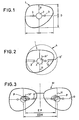
- a caliber 1 is usually drilled in the center of a hole 2 and also includes two small holes 3 located at an equal distance from the center of the hole 2 and determining an axis of origin O which is parallel to a straight line joining the pupils of the user when the template is mounted on a pair of glasses worn by the user.
- the template also includes a second axis H orthogonal to axis 0 and passing through the geometric center of the template.
- An optical glass blank designated by the reference 4 in FIG. 2 carries, traced thereon, two orthogonal axes 0 'and H' crossed at the optical center of the blank and which are usually traced by means of an erasable ink.
- the pupils P of a user wearing a frame M are spaced by a distance called pupillary distance EP while the geometric centers of the templates (or circles of the frames) are spaced by a distance EGM representing the geometrical difference of the frame which, in this example, is a little greater than the distance EP.
- an adapter is placed on the center of rotation of the lens which corresponds to the geometric center of the template, in known manner.
- the apparatus according to the invention allows this centering to be carried out with ease and precision.
- This device shown in perspective in Figure 4 includes a support 5 having a keyboard 6, the assembly having for example a shape similar to that of a conventional typewriter.
- the support 5 carries at its upper part a flat electronic screen 7 which is for example a display screen of the liquid crystal type.
- an optical sighting device Opposite the keyboard relative to the screen 7 is mounted an optical sighting device which will be described in more detail below.
- the support 5 contains an electronic assembly constituted by a computer 8 connected to the screen 7 in an appropriate manner, a data bank 9 or other suitable memory system, and a data entry device 10. This electronic assembly is linked to a grinder 11 with numerical control. On the screen 7 is disposed a sheet 12 for example of transparent plastic or glass carrying in its middle two orthogonal axes X, Y which are graduated.
- the keyboard 6 includes a control device 14 which, according to the example shown, consists of keys.
- the device mounted on the rear part of the support 5 comprises a fixed vertical upright 15 on which is slidably mounted an elongated body 16 urged upwards against a stop 17 by means of a spring 18.
- the body 16 has at one end a first arm 19 extending horizontally and at its opposite end a second arm 20 also extending horizontally but offset by 90 ° C relative to arm 19 and of the same length.
- the arm 19 carries at its end an optical device 24, the length of the arm being adapted so that this device 24 can be brought to the vertical of the intersection of the axes X, Y of the sheet 12.
- the arm 20 carries at its end a support 21 adapted to receive an adapter 22 constituted for example by a suction cup in a removable manner.
- the body 16 is rotatably mounted on the axis 15 and can be displaced in height by translation on this axis, by means of a control member 23.
- the screen 7 is displayed on the screen 7 by means of the computer 8 of a chosen frame of which the data are stored in the bank 9.
- the computer having in memory the data corresponding to the chosen frame progressively records the displacements of the shape from its position from the entry or storage position and calculates the differences with respect to the data of the frame and restores the shape of the frame centered according to the pupil position of the user.
- the glass blank is then placed manually on the screen so that its optical center coincides with the intersection of the X, Y axes and is checked by means of the optical device 24 which makes it possible to observe the image without correction of parallax that the image of the mounting circle (or template) is indeed contained in the blank.
- the body 16 of the device is then rotated by 90 ° to bring the adapter 22 into position above the blank and place it thereon.
- the input device 10 contained in the electronic assembly of the device can be a device as described in FR-A-2 229 213 which comprises a probe adapted to follow the contours of a frame circle or a template and send signals which can be entered directly into the computer 8 in place of the data stored in the bank 9.
- the device according to the invention makes it possible, from a frame shape or a chosen template and by entering into the calculator linked to the screen, the particular morphological data of a user, automatically establish the information necessary to order a grinding machine, and also determine the characteristics of the glass: maximum diameter and critical radii for the purchase of special glasses (precalibrated glasses).
- the device according to the invention makes it possible to directly control the grinding machine as a function of the measurements carried out by moving the image of the frame or of the templates on the screen 7 of the device.
- the device according to the invention allows centering to be carried out at the particular dimensions of the end user of the frame and that, if desired, a printer can be connected to the computer 8 in order to print all the dimensions d '' a given lens, intended for the manufacturer to make this lens for a given frame and a given client (pre-calibrated lenses).
- the screen 7 used having a definition of a few tenths of a millimeter, we obtain with the apparatus according to the invention a completely satisfactory precision.
- the computer can be adapted to display the orthogonal axes X, Y directly on the screen.
Landscapes
- Engineering & Computer Science (AREA)
- Mechanical Engineering (AREA)
- Grinding And Polishing Of Tertiary Curved Surfaces And Surfaces With Complex Shapes (AREA)
Claims (7)
Priority Applications (1)
| Application Number | Priority Date | Filing Date | Title |
|---|---|---|---|
| AT86401062T ATE37678T1 (de) | 1985-06-10 | 1986-05-20 | Vorrichtung zum zentrieren und auflegen eines adapters auf einen rohling eines optischen glases sowie zum steuern einer schleifmaschine. |
Applications Claiming Priority (2)
| Application Number | Priority Date | Filing Date | Title |
|---|---|---|---|
| FR8508723A FR2582975B1 (fr) | 1985-06-10 | 1985-06-10 | Appareil pour centrer et poser un adaptateur sur une ebauche de verre optique et pour commander une rectifieuse |
| FR8508723 | 1985-06-10 |
Publications (3)
| Publication Number | Publication Date |
|---|---|
| EP0206860A1 EP0206860A1 (de) | 1986-12-30 |
| EP0206860B1 true EP0206860B1 (de) | 1988-10-05 |
| EP0206860B2 EP0206860B2 (de) | 1996-12-11 |
Family
ID=9320043
Family Applications (1)
| Application Number | Title | Priority Date | Filing Date |
|---|---|---|---|
| EP86401062A Expired - Lifetime EP0206860B2 (de) | 1985-06-10 | 1986-05-20 | Vorrichtung zum Zentrieren und Auflegen eines Adapters auf einen Rohling eines optischen Glases sowie zum Steuern einer Schleifmaschine |
Country Status (6)
| Country | Link |
|---|---|
| US (1) | US4737918A (de) |
| EP (1) | EP0206860B2 (de) |
| JP (1) | JPH0611469B2 (de) |
| AT (1) | ATE37678T1 (de) |
| DE (1) | DE3660852D1 (de) |
| FR (1) | FR2582975B1 (de) |
Cited By (1)
| Publication number | Priority date | Publication date | Assignee | Title |
|---|---|---|---|---|
| DE19601710A1 (de) * | 1995-01-20 | 1996-07-25 | Buchmann Optical Eng | Vorrichtung zur genauen Positionierung eines optischen Glasrohlings sowie Apparat zur zentrierten Positionierung eines Adapters auf einem Rohling |
Families Citing this family (56)
| Publication number | Priority date | Publication date | Assignee | Title |
|---|---|---|---|---|
| DE3829488A1 (de) * | 1988-08-31 | 1990-03-01 | Wernicke & Co Gmbh | Vorrichtung zum zentrieren von brillenglaesern und aufbringen eines halteteils auf diesen sowie anwendung der vorrichtung |
| FR2636143B1 (fr) * | 1988-09-08 | 1990-11-02 | Briot Int | Installation de transmission de donnees, destinee a faciliter et accelerer la fabrication de verres de lunettes |
| ES2014801A6 (es) * | 1989-07-17 | 1990-07-16 | Indo International S A | Aparato para el centrado y bloqueado de lentes oftalmologicas> |
| JPH0822496B2 (ja) * | 1989-10-17 | 1996-03-06 | 株式会社トプコン | レンズ加工方法及びそのための装置 |
| US5155940A (en) * | 1989-10-30 | 1992-10-20 | Kabushiki Kaisha Topcon | Apparatus for judging whether an uncut lens should be machined or not and lens grinding machine having the same |
| JPH0818236B2 (ja) * | 1989-10-30 | 1996-02-28 | 株式会社トプコン | 吸着済レンズの加工可否判定装置およびそれを有する玉摺機 |
| GB2241911B (en) * | 1990-03-14 | 1993-11-17 | Norville Optical Co Ltd | Ophthalmic lens manufacture |
| US5333412A (en) * | 1990-08-09 | 1994-08-02 | Nidek Co., Ltd. | Apparatus for and method of obtaining processing information for fitting lenses in eyeglasses frame and eyeglasses grinding machine |
| FR2676383B1 (fr) * | 1991-05-16 | 1993-09-10 | Buchmann Optical Eng | Dispositif de pose d'un adaptateur sur une ebauche de verre optique. |
| FR2676676B1 (fr) * | 1991-05-22 | 1993-09-10 | Buchmann Optical Eng | Dispositif pour le positionnement precis d'une ebauche de verre. |
| DE4127094C2 (de) * | 1991-08-16 | 1994-09-08 | Wernicke & Co Gmbh | Anlage zum Schleifen der optischen Oberflächen und/oder des Umfangsrandes von Brillengläsern |
| US5257198A (en) * | 1991-12-18 | 1993-10-26 | Schoyck Carol G Van | Method of transmitting edger information to a remote numerically controlled edger |
| FR2685501A1 (fr) * | 1991-12-18 | 1993-06-25 | Essilor Int | Appareil de centrage pour lentille ophtalmique. |
| US5283980A (en) * | 1992-12-04 | 1994-02-08 | Coburn Optical Industries, Inc. | Lens blocker |
| US5425665A (en) * | 1992-12-09 | 1995-06-20 | National Optronics, Inc. | Optical lens blocker and method |
| US5505654A (en) * | 1993-09-07 | 1996-04-09 | Gerber Optical, Inc. | Lens blocking apparatus |
| US5489954A (en) * | 1993-10-06 | 1996-02-06 | Coburn Optical Industries, Inc. | Lens projecting device |
| US5428448A (en) * | 1993-10-20 | 1995-06-27 | Augen Wecken Plasticos S.R.L. De C.V. | Method and apparatus for non-contact digitazation of frames and lenses |
| DE4414784C2 (de) * | 1994-04-28 | 1996-07-18 | Wernicke & Co Gmbh | Anlage zum Schleifen des Umfangsrandes und/ oder einer optischen Oberfläche von Brillengläsern |
| FR2720312B1 (fr) * | 1994-05-24 | 1996-08-14 | Buchmann Optical Eng | Agencement pour la visualisation de la zone du double foyer d'un verre ophtalmique, et appareil comportant un tel agencement. |
| US5498200A (en) * | 1994-08-12 | 1996-03-12 | Wernicke & Co. Gmbh | Device for parallex-free centering of a blank for a glass lens for spectacles and for providing markings and/or attaching a holder before inserting the blank into a grinding machine for blanks for glass lenses |
| US6929364B1 (en) * | 1995-04-04 | 2005-08-16 | Oakley, Inc. | Contoured metal eyeglass frames |
| US5805261A (en) * | 1995-04-04 | 1998-09-08 | Oakley, Inc. | Biased eyeglass frames |
| US5715167A (en) * | 1995-07-13 | 1998-02-03 | General Electric Company | Fixture for calibrated positioning of an object |
| US5815848A (en) * | 1995-07-14 | 1998-10-06 | Oakley, Inc. | Impact resistant face shield for sporting helmets |
| DE19616572C2 (de) * | 1995-08-26 | 1998-03-26 | Wernicke & Co Gmbh | Verfahren und Vorrichtung zum Vermessen eines Brillengestells oder eines Brillenglases oder einer Formscheibe |
| US5648832A (en) * | 1995-12-05 | 1997-07-15 | Oakley, Inc. | Decentered noncorrective lens for eyewear |
| FR2743626B1 (fr) * | 1996-01-17 | 1998-03-20 | Essilor Int | Appareil de lecture de contour, notamment pour verre de lunettes |
| JPH09248746A (ja) * | 1996-03-12 | 1997-09-22 | Takubo Seiki Seisakusho:Kk | 軸打機 |
| US6011630A (en) * | 1996-11-12 | 2000-01-04 | Gerber Optical, Inc. | System and method for blocking a lens |
| DE19702287C2 (de) * | 1997-01-23 | 1999-02-11 | Wernicke & Co Gmbh | Verfahren zum Ermitteln des Facettenverlaufs auf dem Rand von formzubearbeitenden Brillengläsern und zum Steuern des Formbearbeitens entsprechend dem ermittelten Facettenverlauf |
| US6056399A (en) * | 1997-01-29 | 2000-05-02 | Oakley, Inc. | Interchangeable nosepiece system |
| JP2786848B2 (ja) * | 1997-02-07 | 1998-08-13 | 株式会社トプコン | 吸着済レンズの画像表示装置 |
| FR2762247B1 (fr) * | 1997-04-18 | 1999-07-09 | Briot Int | Systeme de fabrication d'un verre optique a partir d'une ebauche |
| ES2136541B1 (es) * | 1997-05-06 | 2000-08-01 | Indo Int Sa | Aparato para el centrado y bloqueo de un disco de lente oftalmica. |
| US5919080A (en) * | 1997-05-30 | 1999-07-06 | Micro Optics Design Corporation | Ophthalmic lens blocker |
| US5956253A (en) * | 1997-09-09 | 1999-09-21 | Glassline Corporation | Camera controlled CNC apparatus for processing blanks |
| US6012965A (en) * | 1997-10-07 | 2000-01-11 | Micro Optics Design Corp. | Manufacturing ophthalmic lenses using lens structure cognition and spatial positioning system |
| DE69920542T3 (de) † | 1998-01-30 | 2012-05-24 | Nidek Co., Ltd. | Vorrichtung zum Anbringen eines Halteteils |
| US6798501B1 (en) | 1998-01-30 | 2004-09-28 | Nidek Co., Ltd. | Cup attaching apparatus |
| JP3929595B2 (ja) | 1998-03-31 | 2007-06-13 | 株式会社ニデック | 眼鏡レンズ加工システム |
| US6009564A (en) * | 1998-06-24 | 2000-01-04 | Oakley, Inc. | Optically corrected goggle |
| FR2792566B1 (fr) * | 1999-04-20 | 2001-08-03 | Briot Int | Procede de pose d'un adaptateur de meulage sur une ebauche de verre de lunettes |
| JP3828686B2 (ja) | 1999-08-31 | 2006-10-04 | 株式会社ニデック | カップ取付装置 |
| FR2799545B1 (fr) * | 1999-10-07 | 2002-01-18 | Briot Int | Procede et appareil de centrage d'une lentille ophtalmique |
| JP3842953B2 (ja) * | 2000-04-28 | 2006-11-08 | 株式会社ニデック | カップ取付け装置 |
| FR2825308B1 (fr) * | 2001-06-05 | 2003-10-10 | Essilor Int | Dispositif automatique ou semi-automatique pour le detourage d'un verre ophtalmique |
| US20040230335A1 (en) * | 2003-05-13 | 2004-11-18 | Gerding David W. | System for capturing shape data for eyeglass lenses, and method for determining shape data for eyeglass lenses |
| FR2866718B1 (fr) * | 2004-02-24 | 2006-05-05 | Essilor Int | Dispositif centreur-bloqueur d'une lentille ophtalmique de lunettes, methode de detection automatique et methodes de centrage manuel associees |
| FR2866719B1 (fr) * | 2004-02-24 | 2006-05-19 | Essilor Int | Methode de contrage manuel d'une lentille ophtalmique de lunettes dans un centreur-bloqueur et dispositif centreur-bloqueur associe |
| FR2866721B1 (fr) * | 2004-02-24 | 2006-05-19 | Essilor Int | Methode de centrage manuel d'une lentille ophtalmique de lunettes avec affichage intermittent d'un signe opaque servant a la correction de l'erreur de deviation prismatique induite par la lentille |
| FR2878043B1 (fr) * | 2004-11-12 | 2007-03-23 | Briot Internat Sa | Systeme de chargement d'informations dans une machine automatisee de taille d'un verre optique a partir d'une ebauche |
| US7448750B2 (en) * | 2006-09-22 | 2008-11-11 | Oakley, Inc. | Quadrilateral lens |
| JP7225645B2 (ja) * | 2018-09-28 | 2023-02-21 | 株式会社ニデック | カップ取付装置 |
| JP7275515B2 (ja) * | 2018-09-28 | 2023-05-18 | 株式会社ニデック | カップ取付装置 |
| IT201900002339A1 (it) * | 2019-02-18 | 2020-08-18 | Thelios S P A | Metodo per realizzare una lente di occhiali rivestita mediante deposizione fisica di vapore pvd e corpo di supporto per uno sbozzato di lente |
Family Cites Families (8)
| Publication number | Priority date | Publication date | Assignee | Title |
|---|---|---|---|---|
| FR1493482A (fr) * | 1966-05-14 | 1967-09-01 | Lunetiers Cottet Poichet Soc D | Dispositif pour la mise en place de verres de lunettes sur la machine à meuler en fonction de l'écartement pupillaire du porteur et de l'entr'axe des arcatures de la monture |
| DE1948644A1 (de) * | 1969-09-26 | 1971-04-01 | Zeiss Carl Fa | Vorrichtung zum Ausrichten einer rohkantigen Linse zur Formschablone ihrer Fassung |
| DE2220373A1 (de) * | 1972-04-26 | 1973-11-15 | Wernicke & Co Kg | Vorrichtung zum zentrieren von brillenglaesern, insbesondere von brillenglaesern mit nahteil, und zum anbringen eines halteteils auf dem brillenglas |
| JPS591143A (ja) * | 1982-06-25 | 1984-01-06 | Hitachi Ltd | レンズ芯取り機 |
| US4524419A (en) * | 1982-09-13 | 1985-06-18 | Intelab Medical Systems, Inc. | System for determining the optimal ground depth of an ophthalmic lens having a closed homeomorphic boundary |
| DE3316619A1 (de) * | 1983-05-06 | 1984-11-08 | Otto 4010 Hilden Helbrecht | Schleifmaschine fuer die raender von brillenglaesern |
| FR2570013B1 (fr) * | 1984-09-11 | 1987-02-13 | Essilor Int | Machine a meuler pour le biseautage ou rainurage guide ou libre d'une lentille ophtalmique |
| US4656590A (en) * | 1984-11-07 | 1987-04-07 | Ronald Ace | Method and apparatus for making patterns for eyeglasses |
-
1985
- 1985-06-10 FR FR8508723A patent/FR2582975B1/fr not_active Expired
-
1986
- 1986-05-20 EP EP86401062A patent/EP0206860B2/de not_active Expired - Lifetime
- 1986-05-20 AT AT86401062T patent/ATE37678T1/de not_active IP Right Cessation
- 1986-05-20 DE DE8686401062T patent/DE3660852D1/de not_active Expired
- 1986-06-04 US US06/870,775 patent/US4737918A/en not_active Expired - Lifetime
- 1986-06-05 JP JP61129338A patent/JPH0611469B2/ja not_active Expired - Lifetime
Cited By (2)
| Publication number | Priority date | Publication date | Assignee | Title |
|---|---|---|---|---|
| DE19601710A1 (de) * | 1995-01-20 | 1996-07-25 | Buchmann Optical Eng | Vorrichtung zur genauen Positionierung eines optischen Glasrohlings sowie Apparat zur zentrierten Positionierung eines Adapters auf einem Rohling |
| DE19601710C2 (de) * | 1995-01-20 | 1998-07-30 | Buchmann Optical Eng | Vorrichtung zum Ausrichten eines optischen Brillenglasrohlinges auf einer ebenen Fläche vor der Anbringung eines Adapters zum Einspannen des Brillenglasrohlinges in einer Brillenglasrandschleifmaschine |
Also Published As
| Publication number | Publication date |
|---|---|
| FR2582975A1 (fr) | 1986-12-12 |
| DE3660852D1 (en) | 1988-11-10 |
| JPS61284372A (ja) | 1986-12-15 |
| US4737918A (en) | 1988-04-12 |
| EP0206860B2 (de) | 1996-12-11 |
| ATE37678T1 (de) | 1988-10-15 |
| FR2582975B1 (fr) | 1987-08-28 |
| EP0206860A1 (de) | 1986-12-30 |
| JPH0611469B2 (ja) | 1994-02-16 |
Similar Documents
| Publication | Publication Date | Title |
|---|---|---|
| EP0206860B1 (de) | Vorrichtung zum Zentrieren und Auflegen eines Adapters auf einen Rohling eines optischen Glases sowie zum Steuern einer Schleifmaschine | |
| EP1392472B1 (de) | Automatische oder halbautomatische maschine für das aussenkonturfräsen einer linse | |
| EP1817562B9 (de) | Einrichtung zum automatischen messen von kenngrössen einer brillenlinse | |
| EP1827756B1 (de) | Vorrichtung zur automatischen befestigungsvorbereitung für ophthalmische linsen, die die gleichzeitige behandlung mehrerer linsen ermöglicht | |
| EP1393036B1 (de) | Vorrichtung zur automatischen feststellung der charakteristiken eines ophthalmiches glass mit einer automatischen positionierungsvorrichtung eines zentrier- und antriebstückes | |
| EP1836025B1 (de) | Verfahren und vorrichtung zur automatischen vorbereitung einer zu befestigenden ophthalmischen linse | |
| EP1827757B1 (de) | Verfahren und vorrichtung zur montagevorbereitung zum einsatz zweier ophthalmischer linsen im selben brillenpaar | |
| FR2905478A1 (fr) | Procede et dispositif de preparation de lntilles de lunettes en vue de leur montage sur la monture choisie par le porteur. | |
| EP1828742A1 (de) | Verfahren und vorrichtung zur lokalen messung der brechungseigenschaften einer linse an einem oder mehreren bestimmten punkten dieser linse | |
| EP1833639A1 (de) | Verfahren und vorrichtung zur automatischen befestigungsvorbereitung einer opthalmischen linse | |
| EP2196845B1 (de) | Verfahren zur Vorbereitung einer ophthalmischen Linse zwecks ihres Einbaus in eine gewölbte Brillenfassung | |
| EP3164759A1 (de) | Verfahren zum betrachten von markierungen auf einer brille | |
| EP0930954B1 (de) | Herstellungssystem einer optischen linse ausgehend von einem rohling | |
| FR3013620A1 (fr) | Procede de biseautage d'une lentille ophtalmique | |
| WO2006061477A1 (fr) | Procede et dispositif de preparation automatique au montage d'une lentille ophtalmique au moyen d'une paire de nez de prehension transfert et blocage | |
| EP1882207B1 (de) | Verfahren zum aufzeichnen von geometrischen kenngrössen einer zweiten linse mittels abtasten einer ersten linse, wobei beide linsen aus derselben charge stammen | |
| FR2878978A1 (fr) | Methode de blocage d'une lentille ophtalmique en vue de son detourage et dispositif de preparation automatique au montage d'une lentille ophtalmique | |
| WO2005092571A1 (fr) | Methode de centrage manuel d'une lentille ophtalmique de lunettes avec affichage intermittent d'un signe opaque servant à la correction de l'erreur de déviation prismatique induite par la lentille | |
| FR2878976A1 (fr) | Procede et dispositif de blocage d'une lentille ophtalmique par dissociation des fonctions de reference de centrage et d'immobilisation |
Legal Events
| Date | Code | Title | Description |
|---|---|---|---|
| PUAI | Public reference made under article 153(3) epc to a published international application that has entered the european phase |
Free format text: ORIGINAL CODE: 0009012 |
|
| 17P | Request for examination filed |
Effective date: 19860521 |
|
| AK | Designated contracting states |
Kind code of ref document: A1 Designated state(s): AT BE CH DE GB IT LI LU NL SE |
|
| 17Q | First examination report despatched |
Effective date: 19871009 |
|
| ITF | It: translation for a ep patent filed |
Owner name: BARZANO' E ZANARDO MILANO S.P.A. |
|
| GRAA | (expected) grant |
Free format text: ORIGINAL CODE: 0009210 |
|
| AK | Designated contracting states |
Kind code of ref document: B1 Designated state(s): AT BE CH DE GB IT LI LU NL SE |
|
| REF | Corresponds to: |
Ref document number: 37678 Country of ref document: AT Date of ref document: 19881015 Kind code of ref document: T |
|
| GBT | Gb: translation of ep patent filed (gb section 77(6)(a)/1977) | ||
| REF | Corresponds to: |
Ref document number: 3660852 Country of ref document: DE Date of ref document: 19881110 |
|
| PLBI | Opposition filed |
Free format text: ORIGINAL CODE: 0009260 |
|
| PLBI | Opposition filed |
Free format text: ORIGINAL CODE: 0009260 |
|
| 26 | Opposition filed |
Opponent name: ESSILOR INTERNATIONAL (COMP. GENERALE D'OPTIQUE) Effective date: 19890608 |
|
| 26 | Opposition filed |
Opponent name: WECO WERNICKE & CO. GMBH, Effective date: 19890704 Opponent name: ESSILOR INTERNATIONAL (COMP. GENERALE D'OPTIQUE) Effective date: 19890608 |
|
| NLR1 | Nl: opposition has been filed with the epo |
Opponent name: ESSILOR INTERNATIONAL (COMP. GENERALE D KOPTIQUE) |
|
| NLR1 | Nl: opposition has been filed with the epo |
Opponent name: WECO WERNICKE & CO. GMBH, |
|
| RAP2 | Party data changed (patent owner data changed or rights of a patent transferred) |
Owner name: BRIOT INTERNATIONAL |
|
| NLT2 | Nl: modifications (of names), taken from the european patent patent bulletin |
Owner name: BRIOT INTERNATIONAL TE PONT DE L'ARCHE, FRANKRIJK. |
|
| REG | Reference to a national code |
Ref country code: CH Ref legal event code: PFA Free format text: BRIOT INTERNATIONAL |
|
| PLAB | Opposition data, opponent's data or that of the opponent's representative modified |
Free format text: ORIGINAL CODE: 0009299OPPO |
|
| ITTA | It: last paid annual fee | ||
| R26 | Opposition filed (corrected) |
Opponent name: ESSILOR INTERNATIONAL (COMP. GENERALE D'OPTIQUE) * Effective date: 19890608 |
|
| EPTA | Lu: last paid annual fee | ||
| EAL | Se: european patent in force in sweden |
Ref document number: 86401062.4 |
|
| PLAW | Interlocutory decision in opposition |
Free format text: ORIGINAL CODE: EPIDOS IDOP |
|
| PUAH | Patent maintained in amended form |
Free format text: ORIGINAL CODE: 0009272 |
|
| STAA | Information on the status of an ep patent application or granted ep patent |
Free format text: STATUS: PATENT MAINTAINED AS AMENDED |
|
| ITF | It: translation for a ep patent filed |
Owner name: BARZANO' E ZANARDO MILANO S.P.A. |
|
| APAC | Appeal dossier modified |
Free format text: ORIGINAL CODE: EPIDOS NOAPO |
|
| APAC | Appeal dossier modified |
Free format text: ORIGINAL CODE: EPIDOS NOAPO |
|
| 27A | Patent maintained in amended form |
Effective date: 19961211 |
|
| AK | Designated contracting states |
Kind code of ref document: B2 Designated state(s): AT BE CH DE GB IT LI LU NL SE |
|
| GBTA | Gb: translation of amended ep patent filed (gb section 77(6)(b)/1977) |
Effective date: 19961211 |
|
| REG | Reference to a national code |
Ref country code: CH Ref legal event code: AEN Free format text: MAINTIEN DU BREVET DONT L'ETENDUE A ETE MODIFIEE |
|
| NLR2 | Nl: decision of opposition | ||
| NLR3 | Nl: receipt of modified translations in the netherlands language after an opposition procedure | ||
| REG | Reference to a national code |
Ref country code: GB Ref legal event code: IF02 |
|
| PGFP | Annual fee paid to national office [announced via postgrant information from national office to epo] |
Ref country code: AT Payment date: 20050414 Year of fee payment: 20 |
|
| PGFP | Annual fee paid to national office [announced via postgrant information from national office to epo] |
Ref country code: SE Payment date: 20050415 Year of fee payment: 20 Ref country code: CH Payment date: 20050415 Year of fee payment: 20 |
|
| PGFP | Annual fee paid to national office [announced via postgrant information from national office to epo] |
Ref country code: NL Payment date: 20050425 Year of fee payment: 20 |
|
| PGFP | Annual fee paid to national office [announced via postgrant information from national office to epo] |
Ref country code: LU Payment date: 20050427 Year of fee payment: 20 |
|
| PGFP | Annual fee paid to national office [announced via postgrant information from national office to epo] |
Ref country code: GB Payment date: 20050506 Year of fee payment: 20 |
|
| PGFP | Annual fee paid to national office [announced via postgrant information from national office to epo] |
Ref country code: DE Payment date: 20050510 Year of fee payment: 20 |
|
| PGFP | Annual fee paid to national office [announced via postgrant information from national office to epo] |
Ref country code: IT Payment date: 20050519 Year of fee payment: 20 |
|
| PGFP | Annual fee paid to national office [announced via postgrant information from national office to epo] |
Ref country code: BE Payment date: 20050609 Year of fee payment: 20 |
|
| APAH | Appeal reference modified |
Free format text: ORIGINAL CODE: EPIDOSCREFNO |
|
| PG25 | Lapsed in a contracting state [announced via postgrant information from national office to epo] |
Ref country code: GB Free format text: LAPSE BECAUSE OF EXPIRATION OF PROTECTION Effective date: 20060519 |
|
| PG25 | Lapsed in a contracting state [announced via postgrant information from national office to epo] |
Ref country code: NL Free format text: LAPSE BECAUSE OF EXPIRATION OF PROTECTION Effective date: 20060520 |
|
| REG | Reference to a national code |
Ref country code: GB Ref legal event code: PE20 |
|
| REG | Reference to a national code |
Ref country code: CH Ref legal event code: PL |
|
| EUG | Se: european patent has lapsed | ||
| NLV7 | Nl: ceased due to reaching the maximum lifetime of a patent |
Effective date: 20060520 |
|
| BE20 | Be: patent expired |
Owner name: *BRIOT INTERNATIONAL Effective date: 20060520 |