EP0203904B1 - Schalungs- und Bewehrungswand - Google Patents
Schalungs- und Bewehrungswand Download PDFInfo
- Publication number
- EP0203904B1 EP0203904B1 EP86870072A EP86870072A EP0203904B1 EP 0203904 B1 EP0203904 B1 EP 0203904B1 EP 86870072 A EP86870072 A EP 86870072A EP 86870072 A EP86870072 A EP 86870072A EP 0203904 B1 EP0203904 B1 EP 0203904B1
- Authority
- EP
- European Patent Office
- Prior art keywords
- plate
- shuttering
- section
- elements
- along
- Prior art date
- Legal status (The legal status is an assumption and is not a legal conclusion. Google has not performed a legal analysis and makes no representation as to the accuracy of the status listed.)
- Expired
Links
- 238000009416 shuttering Methods 0.000 title claims description 32
- 238000005304 joining Methods 0.000 claims description 19
- 238000003780 insertion Methods 0.000 claims description 16
- 230000037431 insertion Effects 0.000 claims description 16
- 239000007787 solid Substances 0.000 claims description 10
- 238000009412 basement excavation Methods 0.000 claims description 5
- 229910052751 metal Inorganic materials 0.000 claims description 3
- 239000002184 metal Substances 0.000 claims description 3
- 239000002861 polymer material Substances 0.000 claims description 3
- 239000004568 cement Substances 0.000 claims description 2
- 210000002105 tongue Anatomy 0.000 claims 11
- 230000000063 preceeding effect Effects 0.000 claims 6
- 238000009415 formwork Methods 0.000 description 90
- 239000004567 concrete Substances 0.000 description 30
- 230000000903 blocking effect Effects 0.000 description 8
- 238000000576 coating method Methods 0.000 description 8
- 239000011248 coating agent Substances 0.000 description 7
- 238000005553 drilling Methods 0.000 description 5
- 229920001971 elastomer Polymers 0.000 description 5
- 210000000078 claw Anatomy 0.000 description 4
- 230000000295 complement effect Effects 0.000 description 4
- 238000004519 manufacturing process Methods 0.000 description 4
- 238000000034 method Methods 0.000 description 3
- 239000002689 soil Substances 0.000 description 3
- 239000010959 steel Substances 0.000 description 3
- 229910001018 Cast iron Inorganic materials 0.000 description 2
- 229910001208 Crucible steel Inorganic materials 0.000 description 2
- 238000004026 adhesive bonding Methods 0.000 description 2
- 229910052782 aluminium Inorganic materials 0.000 description 2
- XAGFODPZIPBFFR-UHFFFAOYSA-N aluminium Chemical compound [Al] XAGFODPZIPBFFR-UHFFFAOYSA-N 0.000 description 2
- 230000005540 biological transmission Effects 0.000 description 2
- 230000006835 compression Effects 0.000 description 2
- 238000007906 compression Methods 0.000 description 2
- 238000006073 displacement reaction Methods 0.000 description 2
- 238000009826 distribution Methods 0.000 description 2
- 230000000694 effects Effects 0.000 description 2
- 230000008595 infiltration Effects 0.000 description 2
- 238000001764 infiltration Methods 0.000 description 2
- 238000005086 pumping Methods 0.000 description 2
- 229920002994 synthetic fiber Polymers 0.000 description 2
- 239000012209 synthetic fiber Substances 0.000 description 2
- 238000003466 welding Methods 0.000 description 2
- 229910000831 Steel Inorganic materials 0.000 description 1
- 239000004809 Teflon Substances 0.000 description 1
- 229920006362 Teflon® Polymers 0.000 description 1
- 229910045601 alloy Inorganic materials 0.000 description 1
- 239000000956 alloy Substances 0.000 description 1
- 239000011324 bead Substances 0.000 description 1
- 230000015572 biosynthetic process Effects 0.000 description 1
- 230000009194 climbing Effects 0.000 description 1
- 238000010276 construction Methods 0.000 description 1
- 238000001816 cooling Methods 0.000 description 1
- 238000005520 cutting process Methods 0.000 description 1
- 230000007547 defect Effects 0.000 description 1
- 239000000806 elastomer Substances 0.000 description 1
- 239000000835 fiber Substances 0.000 description 1
- 239000012530 fluid Substances 0.000 description 1
- 238000010438 heat treatment Methods 0.000 description 1
- 239000000463 material Substances 0.000 description 1
- -1 multiplex Substances 0.000 description 1
- 229920000642 polymer Polymers 0.000 description 1
- 230000002787 reinforcement Effects 0.000 description 1
- 238000004904 shortening Methods 0.000 description 1
- 230000005641 tunneling Effects 0.000 description 1
- 239000002699 waste material Substances 0.000 description 1
- 239000002023 wood Substances 0.000 description 1
Images


Classifications
-
- E—FIXED CONSTRUCTIONS
- E04—BUILDING
- E04G—SCAFFOLDING; FORMS; SHUTTERING; BUILDING IMPLEMENTS OR AIDS, OR THEIR USE; HANDLING BUILDING MATERIALS ON THE SITE; REPAIRING, BREAKING-UP OR OTHER WORK ON EXISTING BUILDINGS
- E04G11/00—Forms, shutterings, or falsework for making walls, floors, ceilings, or roofs
- E04G11/06—Forms, shutterings, or falsework for making walls, floors, ceilings, or roofs for walls, e.g. curved end panels for wall shutterings; filler elements for wall shutterings; shutterings for vertical ducts
- E04G11/062—Forms for curved walls
- E04G11/065—Forms for curved walls with mechanical means to modify the curvature
-
- E—FIXED CONSTRUCTIONS
- E04—BUILDING
- E04G—SCAFFOLDING; FORMS; SHUTTERING; BUILDING IMPLEMENTS OR AIDS, OR THEIR USE; HANDLING BUILDING MATERIALS ON THE SITE; REPAIRING, BREAKING-UP OR OTHER WORK ON EXISTING BUILDINGS
- E04G11/00—Forms, shutterings, or falsework for making walls, floors, ceilings, or roofs
- E04G11/06—Forms, shutterings, or falsework for making walls, floors, ceilings, or roofs for walls, e.g. curved end panels for wall shutterings; filler elements for wall shutterings; shutterings for vertical ducts
- E04G11/062—Forms for curved walls
-
- E—FIXED CONSTRUCTIONS
- E04—BUILDING
- E04G—SCAFFOLDING; FORMS; SHUTTERING; BUILDING IMPLEMENTS OR AIDS, OR THEIR USE; HANDLING BUILDING MATERIALS ON THE SITE; REPAIRING, BREAKING-UP OR OTHER WORK ON EXISTING BUILDINGS
- E04G11/00—Forms, shutterings, or falsework for making walls, floors, ceilings, or roofs
- E04G11/06—Forms, shutterings, or falsework for making walls, floors, ceilings, or roofs for walls, e.g. curved end panels for wall shutterings; filler elements for wall shutterings; shutterings for vertical ducts
- E04G11/08—Forms, which are completely dismantled after setting of the concrete and re-built for next pouring
- E04G11/087—Fill-in form panels in the plane of two adjacent forms
-
- E—FIXED CONSTRUCTIONS
- E21—EARTH OR ROCK DRILLING; MINING
- E21D—SHAFTS; TUNNELS; GALLERIES; LARGE UNDERGROUND CHAMBERS
- E21D11/00—Lining tunnels, galleries or other underground cavities, e.g. large underground chambers; Linings therefor; Making such linings in situ, e.g. by assembling
- E21D11/04—Lining with building materials
- E21D11/10—Lining with building materials with concrete cast in situ; Shuttering also lost shutterings, e.g. made of blocks, of metal plates or other equipment adapted therefor
- E21D11/102—Removable shuttering; Bearing or supporting devices therefor
Definitions
- the present invention will be described below with reference to its preferred application which is the production of formwork for the execution of tunnel coatings of concrete poured in place, and, more particularly, in the case of tunnels made in underground excavations.
- the coating is carried out at the same work rate as the tunneling, by pumping fresh concrete into the free space between the machine shield and the concrete already poured and which is hardening, maintained by the fitted formwork.
- the advancement jacks to rest on the lining of the tunnel by means of the mounted formwork.
- the longitudinal forces of propulsion of the shield thus pass by friction between said formwork and the concrete in the lining of the tunnel, which makes it possible to work with a finite length of formwork, the formwork being able to be dismantled when the concrete is hard.
- GB Patent No. 954,595 describes a tunnel lining formed by one or more annular sections which are each formed by the assembly of concrete segments (or section parts). Each section consists of a number of these segments and a key. The joints between these segments are curved and parallel to the axis of the section and allow a certain relative movement between the segments. The key is placed between two segments by a longitudinal translational movement parallel to the axis of the section.
- each section consists of at least two parts assembled end to end in a rigid or articulated manner so that the joining edges are parallel to the axis of the section (and of the tunnel), in order to facilitate its transport and all placement operations inside the tunnel.
- One of these parts therefore at least comprises a curved portion.
- the parts which constitute the sections of formwork are made of cast iron, steel or concrete. These parts are, therefore, heavy and bulky, therefore difficult to handle and have a fixed arcuate shape and cannot be modified.
- the object of the present invention is a formwork and shielding wall which is easy to handle and place, which, while allowing the transmission of the compressive, tensile and shear forces, both transverse and longitudinal, caused by the advancement of the shield.
- the drilling machine and by pouring and setting the concrete is constructed from a maximum of standard recoverable elements which can be used repeatedly, does not require the use of an additional formwork skin and can be adapt to all desired shapes, and to all dimensions of tunnels, by varying the number of standard elements used.
- the standard elements are relatively small in size and weight, and can therefore be easily manipulated by the force of the arms and therefore without the use of lifting devices, etc.
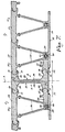
- the stiffening core is connected to the formwork plate by means of two V-shaped connecting elements, which can be either solid webs or reticular structures.
- the formwork plate carries, on its face opposite to the formwork surface, two parallel ribs provided, along their free edge, with a solid cylindrical knot, and the free edge of each of connecting elements of the triangular prismatic structure is provided with a hollow imprint of said node, the nesting of said two nodes in said imprints thus allowing the assembly of a main element.
- the formwork plate can be connected to the integral V-shaped structure either by welding or by gluing.
- the means for assembling the end elements with the key each consist of a plate, one face of which constitutes a sliding surface compatible with one of the sliding surfaces of the key, and of an intermediate plate. allowing attachment to the nearest end element.
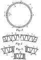
- Fig. 2 shows, on a larger scale, the section, with partial cutaway, of a portion of section 3 (or 4, the parts 3 and 4 being identical), constituted by the edge-to-edge assembly of a number of main elements 7 and having an end element 8 at one end, and an end element 9 at the other, these end elements 8 and 9 allowing assembly with the nearest end element 8 , 9 of a part of a neighboring section.
- Each element 7 comprises a plate 14, the edges of which are parallel to the axis of the section are provided with joining means allowing articulation with neighboring elements.
- the ends of the section portions 2 and 5 between which the key 6 must be inserted have surfaces 41 and 42 respectively, capable of allowing the insertion of the key 6 from the interior of the tunnel to the excavated soil.
Landscapes
- Engineering & Computer Science (AREA)
- Architecture (AREA)
- Structural Engineering (AREA)
- Civil Engineering (AREA)
- Mechanical Engineering (AREA)
- Mining & Mineral Resources (AREA)
- Life Sciences & Earth Sciences (AREA)
- General Life Sciences & Earth Sciences (AREA)
- Geochemistry & Mineralogy (AREA)
- Geology (AREA)
- Lining And Supports For Tunnels (AREA)
- Forms Removed On Construction Sites Or Auxiliary Members Thereof (AREA)
- Moulds, Cores, Or Mandrels (AREA)
Claims (17)
Applications Claiming Priority (2)
| Application Number | Priority Date | Filing Date | Title |
|---|---|---|---|
| FR8507988 | 1985-05-28 | ||
| FR8507988A FR2582718B1 (fr) | 1985-05-28 | 1985-05-28 | Paroi de coffrage et de blindage |
Publications (2)
| Publication Number | Publication Date |
|---|---|
| EP0203904A1 EP0203904A1 (de) | 1986-12-03 |
| EP0203904B1 true EP0203904B1 (de) | 1988-11-02 |
Family
ID=9319607
Family Applications (1)
| Application Number | Title | Priority Date | Filing Date |
|---|---|---|---|
| EP86870072A Expired EP0203904B1 (de) | 1985-05-28 | 1986-05-27 | Schalungs- und Bewehrungswand |
Country Status (6)
| Country | Link |
|---|---|
| US (1) | US4730427A (de) |
| EP (1) | EP0203904B1 (de) |
| CN (1) | CN1003248B (de) |
| BE (1) | BE902530A (de) |
| DE (2) | DE3661090D1 (de) |
| FR (1) | FR2582718B1 (de) |
Families Citing this family (26)
| Publication number | Priority date | Publication date | Assignee | Title |
|---|---|---|---|---|
| EP0378618A4 (en) * | 1988-05-31 | 1991-12-04 | Richard Alexander Carr | Modular moulding system |
| US5472295A (en) * | 1992-10-30 | 1995-12-05 | The Victaulic Company Of Japan Limited | Shield tunneling method using flexible segments, flexible segments for shield tunneling method, and flexible segments for secondary application of shield tunneling method |
| US5448860A (en) * | 1993-04-16 | 1995-09-12 | Menke; John L. | Prefabricated observatory dome structure |
| US5470178A (en) * | 1994-02-17 | 1995-11-28 | Weholt; Raymond L. | Insulating tunnel liner system |
| JP3847072B2 (ja) * | 2000-10-13 | 2006-11-15 | 株式会社クボタ | 合成セグメント |
| BRPI0416332A (pt) * | 2003-11-13 | 2007-01-09 | Gustavo Serrano Rodriguez | trabalho de perfiladura metálico do tipo modular e com painéis modulares |
| ES2336516B1 (es) * | 2007-06-13 | 2011-03-11 | Alpi Sistemas, S.L. | Sistema de encofrado perdido de material plastico. |
| JP5463077B2 (ja) * | 2008-07-17 | 2014-04-09 | 株式会社湘南合成樹脂製作所 | 更生管用セグメント |
| US8016518B2 (en) * | 2008-09-25 | 2011-09-13 | Terra Technologies, LLC | Sheet pile for the subterranean support of underground conduits |
| US8342778B2 (en) * | 2009-04-16 | 2013-01-01 | Hercules Machinery Corporation | Method and apparatus for facilitating the subterranean support of underground conduits having a fixed insertion axis |
| JP5457130B2 (ja) * | 2009-06-03 | 2014-04-02 | 株式会社湘南合成樹脂製作所 | 既設管の更生工法 |
| US8096733B2 (en) * | 2009-07-10 | 2012-01-17 | Hercules Machinery Corporation | Apparatus for inserting sheet pile having an independently adjustable insertion axis and method for using the same |
| CN102022127B (zh) * | 2010-11-08 | 2013-03-13 | 中铁隧道集团有限公司 | 一种隧道施工用的拱架安装设备 |
| NL2008020C2 (nl) | 2011-12-22 | 2013-06-26 | Gte B V | Werkwijze voor het vormen van een buisvormig constructie-element. |
| FR2992010B1 (fr) * | 2012-06-14 | 2016-03-04 | Hussor | Raidisseur pour paroi deformable d'une banche |
| CN105735634A (zh) * | 2016-03-31 | 2016-07-06 | 大连交通大学 | 一种可活动式拱模结构及其安装方法 |
| CN105822059B (zh) * | 2016-04-26 | 2019-01-04 | 王洋 | 一种模板架总成 |
| CN105945479A (zh) * | 2016-05-24 | 2016-09-21 | 中交航局第四工程有限公司 | 拱式胎膜架及利用拱式胎膜架制作盾构管片钢筋笼的方法 |
| CN106677800B (zh) * | 2016-12-21 | 2019-01-11 | 中国水电建设集团十五工程局有限公司 | 大型隧洞变截面段砼衬砌施工方法 |
| CN107795120B (zh) * | 2017-10-21 | 2024-04-02 | 广西广投同力德科技有限公司 | 多曲面自由伸缩建筑模架系统设备 |
| CN108296661B (zh) * | 2018-01-24 | 2024-01-09 | 中国核工业华兴建设有限公司 | 一种弧形双层钢面板结构立式制作方法及其制作工装 |
| CN110778336A (zh) * | 2019-11-07 | 2020-02-11 | 四川省交通勘察设计研究院有限公司 | 一种多重体系的半装配式隧道衬砌结构及其施工方法 |
| CN113982629B (zh) * | 2021-10-29 | 2024-04-05 | 成都未来智隧科技有限公司 | 隧道支护结构 |
| CN114541389B (zh) * | 2022-03-22 | 2022-10-04 | 北京市地质工程有限责任公司 | 一种人工挖孔桩的护壁结构及其施工方法 |
| CN115263365B (zh) * | 2022-08-04 | 2023-09-29 | 广东省水利水电第三工程局有限公司 | 一种适用于箱涵结构的智能台车的灵活组合方式 |
| CN115288430A (zh) * | 2022-08-15 | 2022-11-04 | 中国建筑第八工程局有限公司 | 柱模板安装加固装置及其加固方法 |
Family Cites Families (18)
| Publication number | Priority date | Publication date | Assignee | Title |
|---|---|---|---|---|
| US1197140A (en) * | 1914-10-10 | 1916-09-05 | Richard E Findlay | Section or block for sewer or conduit construction. |
| US1353274A (en) * | 1917-05-12 | 1920-09-21 | Henry W Schlueter | Tunnel construction |
| US3102367A (en) * | 1957-09-18 | 1963-09-03 | Peter S Pedersen | Building block |
| GB954595A (en) * | 1962-01-15 | 1964-04-08 | Kinnear Moodie & Company Ltd | Improvements in or relating to prefabricated concrete tunnel or like shaft linings |
| FR1569600A (de) * | 1967-11-17 | 1969-06-06 | ||
| US3488965A (en) * | 1968-05-02 | 1970-01-13 | Gilbert F Chesnov | Modular brace for shaft liner retention |
| FR1588873A (de) * | 1968-08-27 | 1970-03-16 | ||
| FR2028855A1 (de) * | 1969-01-22 | 1970-10-16 | Holzmann Philipp Ag | |
| CA953937A (en) * | 1970-01-19 | 1974-09-03 | Ivan I. Melnikov | Device for erection of pressed monolithic lining in underworkings |
| AT329620B (de) * | 1971-02-27 | 1976-05-25 | Hoesch Ag | Bogen- oder ringausbau fur die wasserdichte auskleidung von unterirdischen strecken, tunneln, stollen, schachten od.dgl. |
| US3710581A (en) * | 1971-07-06 | 1973-01-16 | Reynolds Metals Co | Tubular construction |
| BE792501A (fr) * | 1971-12-22 | 1973-03-30 | Walbroehl H T | Procede et coffrage pour la realisation du revetement en beton de galeries, tunnels, puits, etc. |
| AT354055B (de) * | 1974-06-01 | 1979-12-27 | Maier Josef | Grossflaechenschalung |
| DE2546755C3 (de) * | 1975-10-18 | 1981-02-19 | Gewerkschaft Eisenhuette Westfalia, 4670 Luenen | Verfahren und Einrichtung zum Betrieb eines Verbauschildes |
| ATE5988T1 (de) * | 1979-06-25 | 1984-02-15 | Pantex-Stahl Ag. | Tuebbingausbau, verwendung dieses tuebbingausbaues und verfahren zu dessen herstellung. |
| GB2094860B (en) * | 1981-03-14 | 1985-01-23 | Dunlop Ltd | Lining of tubular structures |
| GB2108187B (en) * | 1981-10-19 | 1985-10-02 | Tileman And Co Ltd | Concrete forming apparatus |
| US4454693A (en) * | 1982-03-05 | 1984-06-19 | Rochester Silo, Inc. | Continuous-unloading silo |
-
1985
- 1985-05-28 FR FR8507988A patent/FR2582718B1/fr not_active Expired
- 1985-05-29 BE BE0/215093A patent/BE902530A/fr unknown
-
1986
- 1986-05-22 US US06/866,048 patent/US4730427A/en not_active Expired - Fee Related
- 1986-05-27 DE DE8686870072T patent/DE3661090D1/de not_active Expired
- 1986-05-27 EP EP86870072A patent/EP0203904B1/de not_active Expired
- 1986-05-27 DE DE198686870072T patent/DE203904T1/de active Pending
- 1986-05-28 CN CN86103897A patent/CN1003248B/zh not_active Expired
Also Published As
| Publication number | Publication date |
|---|---|
| DE203904T1 (de) | 1987-04-30 |
| CN1003248B (zh) | 1989-02-08 |
| US4730427A (en) | 1988-03-15 |
| BE902530A (fr) | 1985-09-16 |
| CN86103897A (zh) | 1987-03-11 |
| FR2582718B1 (fr) | 1987-08-28 |
| EP0203904A1 (de) | 1986-12-03 |
| DE3661090D1 (en) | 1988-12-08 |
| FR2582718A1 (fr) | 1986-12-05 |
Similar Documents
| Publication | Publication Date | Title |
|---|---|---|
| EP0203904B1 (de) | Schalungs- und Bewehrungswand | |
| EP0081402B1 (de) | Verfahren zur Herstellung von hohlen Elementen wie etwa Leitungen, Silos oder Bunkern | |
| WO1998003737A1 (fr) | Element prefabrique en beton pour la construction d'un ouvrage d'art a paroi voutee | |
| EP2483476B1 (de) | Transversale verbindungsstelle mit zwei gegenüberstehenden transversalen enden von zwei fortlaufenden vorgefertigten fahrbahnelementen und verbindungssystem dafür | |
| CH642416A5 (fr) | Procede de construction d'ouvrages souterrains a parois verticales, dispositif pour l'execution du procede et ouvrage souterrain. | |
| EP0244890B2 (de) | Verfahren zur Herstellung von hohlen Elementen, wie etwa Leitungen, Silos oder Bunker und Elemente, hergestellt durch dieses Verfahren | |
| EP0065486B1 (de) | Längliches Werk mit konstantem Querschnitt und Verfahren zum Bauen dieses Werkes | |
| EP0883719A1 (de) | Schalung für eine betonwand | |
| EP0392912B1 (de) | Fluidtransportleitung | |
| EP0767881B1 (de) | Flüssigkeitsrohr | |
| FR2687711A1 (fr) | Procede de construction d'un edifice, tel qu'abri souterrain, par assemblage d'elements prefabriques. | |
| FR3023867A1 (fr) | Voussoir special pour un revetement pour un tunnel, ensemble de tels voussoirs speciaux, revetement comprenant un tel ensemble et procede associe | |
| EP0774027B1 (de) | Unterirdischer durchgang | |
| EP2563975B1 (de) | Formteilwand mit fertigteilverkleidung | |
| FR2852662A1 (fr) | Procede d'installation d'armatures de precontrainte autour d'une conduite cylindrique enterree | |
| FR3097886A1 (fr) | Système constructif en BFUP / Element tubulaire composite | |
| EP0584298B1 (de) | Langförmige abdeckung grossen durchmessers sowie herstellungsverfahren | |
| FR2617881A1 (fr) | Procede pour realiser une paroi moulee dans le sol et coffrages destines notamment a sa mise en oeuvre | |
| FR2740806A1 (fr) | Procede et dispositif de construction de piscine | |
| FR2547607A1 (fr) | Procede d'obtention de conduits souterrains de grande section, se trouvant sous forte couverture, et conduits obtenus par ce procede | |
| FR2542780A1 (fr) | Procede et dispositif pour ameliorer la jonction entre panneaux successifs d'une paroi en beton arme moulee dans des terrains | |
| FR2647486A1 (fr) | Buse arche en beton arme | |
| BE505786A (de) |
Legal Events
| Date | Code | Title | Description |
|---|---|---|---|
| PUAI | Public reference made under article 153(3) epc to a published international application that has entered the european phase |
Free format text: ORIGINAL CODE: 0009012 |
|
| AK | Designated contracting states |
Kind code of ref document: A1 Designated state(s): BE CH DE FR GB LI LU NL |
|
| 17P | Request for examination filed |
Effective date: 19861107 |
|
| TCNL | Nl: translation of patent claims filed | ||
| DET | De: translation of patent claims | ||
| 17Q | First examination report despatched |
Effective date: 19871105 |
|
| RAP1 | Party data changed (applicant data changed or rights of an application transferred) |
Owner name: COMPAGNIE INTERNATIONALE DES PIEUX ARMES FRANKIG Owner name: COMPAGNIE D'ENTREPRISES CFE, S.A. |
|
| GRAA | (expected) grant |
Free format text: ORIGINAL CODE: 0009210 |
|
| AK | Designated contracting states |
Kind code of ref document: B1 Designated state(s): BE CH DE FR GB LI LU NL |
|
| GBT | Gb: translation of ep patent filed (gb section 77(6)(a)/1977) | ||
| REF | Corresponds to: |
Ref document number: 3661090 Country of ref document: DE Date of ref document: 19881208 |
|
| PLBE | No opposition filed within time limit |
Free format text: ORIGINAL CODE: 0009261 |
|
| STAA | Information on the status of an ep patent application or granted ep patent |
Free format text: STATUS: NO OPPOSITION FILED WITHIN TIME LIMIT |
|
| 26N | No opposition filed | ||
| PGFP | Annual fee paid to national office [announced via postgrant information from national office to epo] |
Ref country code: GB Payment date: 19910522 Year of fee payment: 6 |
|
| PGFP | Annual fee paid to national office [announced via postgrant information from national office to epo] |
Ref country code: CH Payment date: 19910531 Year of fee payment: 6 |
|
| PGFP | Annual fee paid to national office [announced via postgrant information from national office to epo] |
Ref country code: LU Payment date: 19910621 Year of fee payment: 6 |
|
| PGFP | Annual fee paid to national office [announced via postgrant information from national office to epo] |
Ref country code: DE Payment date: 19910731 Year of fee payment: 6 |
|
| EPTA | Lu: last paid annual fee | ||
| PG25 | Lapsed in a contracting state [announced via postgrant information from national office to epo] |
Ref country code: LU Free format text: LAPSE BECAUSE OF NON-PAYMENT OF DUE FEES Effective date: 19920527 Ref country code: GB Effective date: 19920527 |
|
| PG25 | Lapsed in a contracting state [announced via postgrant information from national office to epo] |
Ref country code: LI Effective date: 19920531 Ref country code: CH Effective date: 19920531 |
|
| GBPC | Gb: european patent ceased through non-payment of renewal fee |
Effective date: 19920527 |
|
| REG | Reference to a national code |
Ref country code: CH Ref legal event code: PL |
|
| PG25 | Lapsed in a contracting state [announced via postgrant information from national office to epo] |
Ref country code: DE Effective date: 19930202 |
|
| PGFP | Annual fee paid to national office [announced via postgrant information from national office to epo] |
Ref country code: FR Payment date: 19940317 Year of fee payment: 9 |
|
| PGFP | Annual fee paid to national office [announced via postgrant information from national office to epo] |
Ref country code: BE Payment date: 19940527 Year of fee payment: 9 |
|
| PGFP | Annual fee paid to national office [announced via postgrant information from national office to epo] |
Ref country code: NL Payment date: 19940531 Year of fee payment: 9 |
|
| PG25 | Lapsed in a contracting state [announced via postgrant information from national office to epo] |
Ref country code: BE Effective date: 19950531 |
|
| BERE | Be: lapsed |
Owner name: CIE INTERNATIONALE DES PIEUX ARMES FRANKIGNOUL Effective date: 19950531 Owner name: S.A. CIE D'ENTREPRISES CFE Effective date: 19950531 |
|
| PG25 | Lapsed in a contracting state [announced via postgrant information from national office to epo] |
Ref country code: NL Effective date: 19951201 |
|
| NLV4 | Nl: lapsed or anulled due to non-payment of the annual fee |
Effective date: 19951201 |
|
| PG25 | Lapsed in a contracting state [announced via postgrant information from national office to epo] |
Ref country code: FR Effective date: 19960229 |
|
| REG | Reference to a national code |
Ref country code: FR Ref legal event code: ST |
|
| REG | Reference to a national code |
Ref country code: FR Ref legal event code: ST |