EP0584298B1 - Langförmige abdeckung grossen durchmessers sowie herstellungsverfahren - Google Patents
Langförmige abdeckung grossen durchmessers sowie herstellungsverfahren Download PDFInfo
- Publication number
- EP0584298B1 EP0584298B1 EP93902376A EP93902376A EP0584298B1 EP 0584298 B1 EP0584298 B1 EP 0584298B1 EP 93902376 A EP93902376 A EP 93902376A EP 93902376 A EP93902376 A EP 93902376A EP 0584298 B1 EP0584298 B1 EP 0584298B1
- Authority
- EP
- European Patent Office
- Prior art keywords
- slab
- arch
- plates
- lateral
- longitudinal
- Prior art date
- Legal status (The legal status is an assumption and is not a legal conclusion. Google has not performed a legal analysis and makes no representation as to the accuracy of the status listed.)
- Expired - Lifetime
Links
Images


Classifications
-
- E—FIXED CONSTRUCTIONS
- E02—HYDRAULIC ENGINEERING; FOUNDATIONS; SOIL SHIFTING
- E02D—FOUNDATIONS; EXCAVATIONS; EMBANKMENTS; UNDERGROUND OR UNDERWATER STRUCTURES
- E02D29/00—Independent underground or underwater structures; Retaining walls
- E02D29/045—Underground structures, e.g. tunnels or galleries, built in the open air or by methods involving disturbance of the ground surface all along the location line; Methods of making them
- E02D29/05—Underground structures, e.g. tunnels or galleries, built in the open air or by methods involving disturbance of the ground surface all along the location line; Methods of making them at least part of the cross-section being constructed in an open excavation or from the ground surface, e.g. assembled in a trench
-
- E—FIXED CONSTRUCTIONS
- E02—HYDRAULIC ENGINEERING; FOUNDATIONS; SOIL SHIFTING
- E02B—HYDRAULIC ENGINEERING
- E02B9/00—Water-power plants; Layout, construction or equipment, methods of, or apparatus for, making same
- E02B9/02—Water-ways
- E02B9/06—Pressure galleries or pressure conduits; Galleries specially adapted to house pressure conduits; Means specially adapted for use therewith, e.g. housings, valves, gates
-
- Y—GENERAL TAGGING OF NEW TECHNOLOGICAL DEVELOPMENTS; GENERAL TAGGING OF CROSS-SECTIONAL TECHNOLOGIES SPANNING OVER SEVERAL SECTIONS OF THE IPC; TECHNICAL SUBJECTS COVERED BY FORMER USPC CROSS-REFERENCE ART COLLECTIONS [XRACs] AND DIGESTS
- Y02—TECHNOLOGIES OR APPLICATIONS FOR MITIGATION OR ADAPTATION AGAINST CLIMATE CHANGE
- Y02E—REDUCTION OF GREENHOUSE GAS [GHG] EMISSIONS, RELATED TO ENERGY GENERATION, TRANSMISSION OR DISTRIBUTION
- Y02E10/00—Energy generation through renewable energy sources
- Y02E10/20—Hydro energy
-
- Y—GENERAL TAGGING OF NEW TECHNOLOGICAL DEVELOPMENTS; GENERAL TAGGING OF CROSS-SECTIONAL TECHNOLOGIES SPANNING OVER SEVERAL SECTIONS OF THE IPC; TECHNICAL SUBJECTS COVERED BY FORMER USPC CROSS-REFERENCE ART COLLECTIONS [XRACs] AND DIGESTS
- Y02—TECHNOLOGIES OR APPLICATIONS FOR MITIGATION OR ADAPTATION AGAINST CLIMATE CHANGE
- Y02P—CLIMATE CHANGE MITIGATION TECHNOLOGIES IN THE PRODUCTION OR PROCESSING OF GOODS
- Y02P70/00—Climate change mitigation technologies in the production process for final industrial or consumer products
- Y02P70/50—Manufacturing or production processes characterised by the final manufactured product
Definitions
- the subject of the invention is an elongated enclosure of large cross section, capable of withstanding a high internal pressure, possibly greater than 10 bars, as well as external stresses, and applies more particularly to the production of a fluid transfer pipe. under pressure, intended to be produced in the open air and possibly buried under an embankment.
- the invention can be applied to the production of any pipe with a high flow rate of transfer of pressurized fluid, for example for the production of sanitation or water supply systems, district heating. , or penstocks for the supply of hydroelectric factories.
- the fluid transfer pipes are generally produced by means of sections of metal tubes, of circular cross section, which are placed end to end and connected in a sealed manner.
- the pipe is placed at the bottom of a trench and buried under an embankment.
- the trench is backfilled before pressurizing the pipe which is thus subjected, empty, to external stresses applied by the backfill and possible overloads. After commissioning, these external stresses are compensated for by the internal pressure, but this can vary and sometimes be eliminated. In all these cases, the applied load can cause ovalization and even crushing of the pipe.
- buried pipes are usually made up either of fairly thick metal tubes with external stiffeners, or of reinforced concrete tubes with or without prestressing.
- the metal vault when the pipe is under pressure, the metal vault is subjected only to tensile forces and can be made up of thin metal wall elements of relatively small thickness, easy to handle and which can be connected by welding to ensure sealing under pressure.
- the flat base which serves as a stiffener, is subjected to bending forces, but can resist it under good conditions because it consists of a concrete slab whose thickness and reinforcement can be determined according to sustained efforts.
- a flat base gives the pipe a good seating surface allowing the forces applied to the ground to be distributed and to resist differential settlement.
- the slab can advantageously be cast in place, on advancement, or else be made up of prefabricated elements placed one after the other. other.
- the metal vault is connected to the slab, along its two lateral edges, by profiles comprising an upper part tangentially connecting to the vault and a lower part sealed on the upper face of the slab in a way that makes it possible to resist the tearing forces and, at the same time, to ensure sealing.
- Such a method of attachment is well suited to the case where the slab consists of prefabricated elements, but can complicate the production when the slab is cast in place. In addition, for high internal pressures, one may fear, in the long run, cracking of the concrete, taking into account the applied forces.
- the subject of the invention is therefore new provisions which make it possible to simplify the method of fixing the metal vault, to reduce the risks of cracking of the concrete and to lighten the slab.
- the production of the entire pipe can be considerably simplified by the implementation of these new provisions.
- the invention therefore applies, in general, to an elongated enclosure of the type described in patent EP 0392,912, consisting of a lower part formed by a rigid concrete slab, comprising a lower face resting on the ground. , an upper face and two lateral faces parallel to the longitudinal axis, and an upper part consisting of a thin metal wall in the form of a curved arch extending between two lateral ends parallel to the longitudinal axis and connected to the slab, each by a longitudinal junction piece having an upper part which is connected tangentially to the lateral end of the vault and a lower part fixed to the slab.
- the upper face of the slab has a width substantially equal to the spacing between the two lateral ends of the curved arch and each junction piece is constituted by a flat plate applied from the outside against the lateral face. corresponding to the slab and associated with holding means capable of opposing the sliding of said plate along the corresponding lateral face of the slab under the effect of the forces due to the internal pressure and the detachment of said plates under the effect of external stresses.
- the vault substantially covers a semicircle centered substantially at the level of the upper face of the slab.
- the vault may be advantageous to give the vault an angle at the center greater than 180 °.
- the two lateral faces of the slab can be inclined with respect to the horizontal upper face by an angle corresponding to the orientation of the tangent at the start of the arch, so as to allow the application of the two plates lateral fixing of the vault, placed in the extension thereof.
- the longitudinal fixing plates are applied against the lateral faces of the slab under a pressure at least sufficient to oppose, by friction, the sliding of the plate.
- the two longitudinal plates for fixing the vault to the slab can be connected together by a plurality of transverse bars distributed over the entire length of the enclosure and each extending over the entire width of the slab, passing through the two plates and the slab, each bar being provided, at each end, with an external means of bearing on the corresponding plate, said bars being subjected to a prestressing tension capable of simultaneously ensuring the resistance of the slab to bending forces due to internal pressure and the application of each fixing plate to the corresponding lateral face of the slab under sufficient pressure to oppose the sliding of the plate.
- the tubular enclosure is entirely limited by metal walls welded together.
- the two lateral ends of the vault are connected to each other by a thin transverse plate covering one of the horizontal faces, respectively upper or lower, of the slab and comprising two parallel longitudinal edges rigidly fixed and sealingly, respectively along each lateral end of the arch.
- This transverse plate therefore simultaneously seals and maintains the longitudinal plates, in particular to oppose their separation under the effect of external stresses.
- each fixing plate can be advantageously provided, on its turned internal face towards the slab, at least one projecting hooking part, such as a rib, cooperating with at least one conjugate hollow part, such as a groove, formed at the desired level on the corresponding lateral face of the slab .
- each vault section comprises a central part in the form of a half-shell constituting the vault proper and extended, on each side, by a substantially flat part constituting the fixing flange, each half-shell constituting, with its two flanges, a single piece covering the entire cross section.
- the vault can also consist of at least three prefabricated elements, respectively at least one curved central element in the form of a vault and two lateral elements, each comprising a flat lower part forming the fixing plate. on the corresponding side face of the slab and an upper part capable of tangentially connecting to a lateral edge of the central element and connected to the latter by a continuous weld.
- this upper part of the plate projecting above the level of the upper face of the slab advantageously constitutes a centering rim of the arch element.
- the two longitudinal plates can be fixed in advance on a transverse plate so as to constitute a prefabricated assembly capable of being placed separately on the slab, the arch element then being fixed on the upper edges of the two longitudinal plates.
- the transverse plate can, moreover, consist of two separate parts welded, respectively, each on one of the lateral elements and extending towards one another, partially overlapping so as to allow a slight approximation of the lateral elements when fixed to the slab and when prestressed, the two parts of the transverse plate being welded after stabilization.
- Such an elongated enclosure can be produced in different ways.
- a continuous slab of reinforced or prestressed concrete is produced on advancement, which can be poured in place between two flat forms, the spacing of which, at least at the level of the upper face of the slab, is substantially equal to the spacing between the lateral ends of the circular sector and, to make each section of the metallic upper part, one applies to the lateral faces of the slab, two longitudinal plates which are welded to the ends of the plates already laid and the vault section is laid by welding it, on the one hand, along the transverse joint with the previously laid section and, on the other hand, on the upper ends of the longitudinal plates.
- this can be welded in advance to two of the longitudinal plates so as to form a junction assembly which can be placed on the slab and slide the along it until contact with the previously installed assembly with which it is welded.
- junction assembly can also be used as a formwork in which the corresponding part of the slab is molded, which then consists of prefabricated elements placed one after the other, each element consisting of a junction assembly. associated with a slab element.
- To make a new section of the enclosure first lay a slab element by aligning it with the part already laid, weld the facing edges of the longitudinal plates and transverse plates, then install the arch on the corresponding assembly by welding it along its lateral ends with the longitudinal plates and along a transverse joint with the adjacent arch element already in place.
- the metal part of the enclosure consists of prefabricated sections each comprising a curved wall extended by two longitudinal plates and the lower edges of which are connected by a transverse plate.
- the metal part of the enclosure consists of prefabricated sections each comprising a curved wall extended by two longitudinal plates and the lower edges of which are connected by a transverse plate.
- Such an embodiment can be further improved by connecting the two longitudinal plates by two transverse walls fixed respectively along the lower edges and along the upper ends of the longitudinal plates.
- the assembly of the two transverse walls and the two longitudinal plates thus forms a metal box with closed section which is filled with concrete so as to constitute the slab, the latter being reinforced by the metal wall of said box.
- the site will be equipped with a bender allowing the vault elements to be produced on site, the sheets being thus transported flat.
- This bender can also be placed on the already concrete slab.
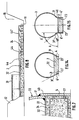
- Figure 1 is a schematic view, in cross section, of an elongated enclosure according to the invention.
- Figure 2 is a cross-sectional figure of another embodiment.
- Figure 3 is a detail view on an enlarged scale of the fixing of a plate by prestressing.
- FIGS 4 and 5 schematically represent, in cross section, other modes for producing an enclosure according to the invention.
- Figure 6 shows, in two stages, the production of a prefabricated lower element.
- Figure 7 is a detail view of a particular method of mounting the vault.
- Figures 8, 9, 10, 11 show, schematically, the successive stages of construction of a pipe according to different processes each adapted to one of the embodiments of the enclosure.
- Figure 12 shows, in longitudinal section, a transverse joint between two prefabricated slab elements.
- Figure 13 shows, in perspective, a particular embodiment allowing a gradual change of section.
- Figures 14, 15 and 16 show, in cross section, other embodiments of the invention.
- FIG 1 there is shown schematically and in cross section, an elongated enclosure 1 placed in a trench 10 and resting on the bottom 11 flattened and compacted thereof, the enclosure being covered, after installation, with a embankment 12.
- the enclosure 1 is made up of two parts, respectively a lower part 2 made up of a flat rigid slab made, normally, of reinforced or prestressed concrete, and an upper part 3 made up of a thin metal wall in the shape of a cylindrical vault limiting , with the slab, a tubular space A with a truncated circular section in which a fluid can be circulated at a high pressure P which can, for example, exceed 10 bars.
- the rigid slab 2 is preferably cast in place, when advancing, but it can also consist of prefabricated elements placed end to end.
- the upper part 3 consists of thin metal wall elements forming sections placed one after the other.
- Each section has the shape of a curved vault in an arc between two lateral ends 31, 31 ′, tangentially extended by two flat plates 4, 4 ′.
- the arch 3 covers a semicircle.
- the slab 2 which rests on the ground by its lower face 21, is limited by a horizontal upper face 22 and two lateral faces 23, 23 ', parallel to the axis of the enclosure.
- the side faces 23, 23 ' are vertical.
- other arrangements are possible as will be seen below.
- the width of the upper face 22, which corresponds to the spacing of the lateral faces 23, 23 ', is equal to the distance between the lateral ends 31, 31', of the cylindrical arch 3 that is to say, in the example shown, the diameter of the circular section.
- the two longitudinal plates 4, 4 ', extending downwards the arch 3 can be applied from the outside to the side faces 23, 23', on which they are fixed.
- the arch 3 Under the effect of the radial forces 15 due to the internal pressure P, the arch 3 is subjected to tensile stresses which are taken up at the lateral ends 31, 31 ', by the plates 4, 4'. These can therefore be fixed on slab 2 by means making it possible simply to resist the shifting forces which are exerted along the lateral faces 23, 23 ′ of the slab when the enclosure is pressurized.
- the upper part 3 resists well, by arching effect, to external stresses 13 applied by the fill 12 or overloads, even when the internal pressure is removed. It is simply necessary to keep the spacing of the lateral ends 31, 31 'of the arch 3 constant and this can be easily obtained by means of a thin plate 32 which covers the upper face 22 of the slab 2 and is welded by its lateral edges on the ends 31, 31 'of the arch.
- the horizontal plate 22 forms with the longitudinal plates 4, 4 ', a box which can be secured to the slab 2 by simple sealing tabs distributed over the entire surface.
- the reinforced concrete slab 2 which ensures the stiffening of the enclosure 1, is particularly capable of withstanding the bending forces to which it is subjected. It suffices, in fact, to determine the dimensional characteristics and the reinforcement of the slab according to the forces resulting from the internal pressure.
- the longitudinal plates 4, 4 ' can be applied with a certain pressure on the lateral faces 23, 23', of the slab.
- the tension of the bars 5 may be simply sufficient to secure the connection of the vault 3 with the slab 2, by virtue of the friction generated, and thus resist the tendency to detach and lift the vault under the action of the internal pressure P .
- the bars 5 oppose the tendency for the lateral ends 31, 31 ′ to move apart, under the effect of the external stresses 13 exerted by the fill 12 and ensure the maintenance of the semi-circular shape of the wall 3 which thus resists buckling and the tendency to ovalization under the loads applied by the fill.
- the bars 5 can also constitute prestressing bars put under a sufficient tension to allow the slab 2 to resist the bending forces to which it is subjected under the action of internal pressure P. Thanks to this prestressing, it is possible to significantly reduce the slab 2 and its frame 24.
- the prestressing of the slab 2 can be carried out in a conventional manner, for example as shown in detail in Figure 3.
- Each bar 5 passes with clearance in a channel 53, formed in the thickness of the slab 2, perpendicularly to the two lateral faces 23, 23 ', of the latter.
- Each end 51 of a bar 5 passes through the corresponding plate 4 through an orifice 41 provided for this purpose and is threaded so as to allow the screwing of a nut 52 which bears on the plate 4, by means of an O-ring piece 53 and a support piece 54 of conjugate shapes.
- the bars 5 are put at the desired prestressing tension and they are blocked by means of the nuts 52 then, by a vent 56 provided for this purpose, a cement grout is injected into the channel 53 so as to secure the prestressing bars with slab 2.
- the reinforcement 24 essentially serves to allow the handling of the slab when the latter consists of prefabricated elements and to avoid the risks of cracking, in particular under the effect of prestressing.
- each plate 4, 4' is provided, on its internal face turned towards the slab, with protruding parts constituted, for example, by angles welded 42, which engage in corresponding grooves 25 formed on the side faces 23, 23 ', of the slab.
- the plate 4 is provided with a reinforcement piece 43 which surrounds the orifice 41 and enters a corresponding housing formed on the lateral face 23 of the slab.
- tubular closed space for circulation of the fluid is entirely limited by welded metal walls, according to the arrangement shown in Figure 1.
- the slab 2 is then covered with a transverse plate 32 welded to the lateral ends of the vault 3. Sealing is thus easily carried out, the wall being entirely welded, and contact between the concrete and the transported fluid is avoided.
- the plate 32 As the plate 32 is applied to the slab 2 by the pressure P, it can constitute a simple thin sealing skin as shown in FIG. 3.
- prestressing bars 5 the maintenance of the spacing of the lateral ends 31, 31 ', which can be ensured simply by the plate 32.
- the longitudinal plates 4, 4' can then be fixed on the lateral faces 23, 23 ', of the slab 2, for example by anchor bolts allowing to apply the plates 4, 4 ′, on the lateral faces 23, 23 ′, with a pressure simply sufficient to ensure, by friction, the maintenance of the shape of the arch 3 while preventing the ends 31, 31 ′ from being raised, arch 3.
- the spacing of the longitudinal plates 4, 4 ′ corresponds exactly to that of the lateral faces 23, 23 ′ of the slab.
- Contact can be ensured by adjusting shims, but it is more advantageous, as indicated in FIG. 5, to produce the transverse plate 32 in two parts, a part 32a which extends substantially over the entire width of the slab 2 but is only welded on one side, on one of the longitudinal plates 4 ', and a second part 32b welded by one side on the other longitudinal plate 4 and of width such that its other side covers the 'end of the part 32.
- the two plates 4, 4', associated respectively with the two parts 32b, 32a are placed on the slab 2 without difficulty, 'and can possibly come together for the application of the plates 4 , 4 ', on the faces 23, 23', then, after stabilization, the ends which overlap the two parts 32a, 32b are welded to each other.
- each metal section consists of a vault 3, the ends of which are connected by a base 38 which rests on the ground.
- the slab 2 is then located inside the closed metal wall thus formed and is advantageously poured inside the formwork thus formed by the lower part of the metal structure.
- the vault 3 can be produced in a single assembly as shown in FIG. 1, the semi-cylindrical curved part 3 being simply extended, beyond its lateral ends 31, 31 ′, by parts planes which constitute the two longitudinal fixing plates 4, 4 '. Each half-shell then constitutes, with its two flanges 4, 4 ′, a monobloc element which covers the entire cross section.
- the metal part in several parts, respectively a central element 33 curved in the shape of an arch and the two longitudinal plates 4, 4 ′, of which most of it is applied against the lateral faces 23, 23 ′, and the upper edges 40, 40 ′ of which are connected and are fixed by welds 35 on the lower lateral edges of the central element 33.
- the welds 35, 35 ' can be placed at the lateral ends 31, 31', and the transverse plate 32.
- the curved wall 33 covers the entire vault.
- welds 35, 35 ' can also be placed at a certain distance above the lateral ends 31, 31 ', each longitudinal plate 4, 4', then comprising a flat lower fixing part and a curved upper part 40, 40 ', tangentially connecting to the arch 33.
- connection and the welding can be done edge to edge as indicated in Figures 2 and 5. But it is also possible to provide an overlap of each lateral end 31 (31 ') of the arch by the upper part 40 (40 ') of the plate 4 (4'), as shown in Figure 7. Such an arrangement facilitates the establishment and centering of the arch 3, as will be seen later.
- the two longitudinal plates 4, 4 ′ can be connected in advance with the transverse plate 32 so as to constitute a one-piece metallic assembly 36 with rectangular cross section which can advantageously serve as formwork for the production of a slab element, the way shown in Figure 6.
- the metal assembly 36 thus formed can be turned over to form a mold having the transverse plate 32 for its bottom and the two plates 4, 4 ′ for sides, the other two sides can be closed with removable panels.
- the reinforcement 24 is placed and, where appropriate, tubes 53 'opening into orifices 41, 41' formed in the elements 34, 34 '. Then pour the concrete 25.
- the horizontal plate 32 has been provided, on its face turned towards the inside of the mold, with protruding hooking parts intended to secure the plate with the concrete 25.
- profiles 42 could be placed in advance on the internal faces of the plates 4, 4 ', so as to be incorporated into the concrete during the casting of the slab 2.
- Each slab element 20 thus prefabricated is therefore provided in advance with the transverse plate 32 and the two longitudinal plates 4, 4 ′, on which a vault element 33 can be placed and welded, as shown in the right side of Figure 6.
- FIGS. 8, 9, 10 and 11 each schematically represent the different stages of construction of a pipe according to either of the embodiments previously described.
- Figure 8 shows the construction of a pipe in the most general embodiment shown in Figure 1.
- the trench 10 is first opened over a certain length, leaving a flat and packed bottom 11 which can be covered with clean concrete 15 or a protective sheet of nonwoven fabric.
- the slab 2 is poured in advance using known means, for example for the realization of concrete pavements.
- the reinforcement 24 is first placed between two lateral formwork panels which are advantageously constituted by the fixing plates 4, 4 ′, themselves. As shown in Figure 7, these can be held by the reinforcement 24 by means of support members 28.
- each new plate 4 is fixed by its rear vertical edge 44 to the corresponding front edge of the last plate 4a sealed on the end of the already made slab.
- the next part of the slab 2 is then poured between the plates 4, 4 ′, then the transverse plates 32 are placed, each welding, by its rear transverse edge, to the preceding plate and by its lateral edges to the plates fixing 4, 4 '.
- the plates 32, as well as the plates 4, 4 ′, can be provided, on their internal face, with sealing lugs ensuring the connection with the slab 2.
- the plates 4, 4 ′ are optionally applied under pressure to the lateral faces of the slab 2 by means of anchor bolts or tension bars 5.
- the plates 4, 4 ′ it is advantageous for the plates 4, 4 ′ to extend above the level of the upper face 22 of the slab 2 since their upper parts 40 then form centering flanges facilitating installation of the arch element 33.
- the latter is then welded to the last arch element already laid, along a transverse joint as well as on the fixing plates 4, 4 ', and, optionally, the transverse plate 32, along its lateral ends 31, 31'.
- the enclosure consists solely of the slab cast in place, on advancement, and of metal panels which can be easily transported to the site. These panels can be shaped and formed in the workshop or on site using a bending machine placed near the site or even, directly, on the already concreted slab.
- Such an embodiment is therefore particularly rational and allows rapid and safe installation of the tubular enclosure.
- each arch element 3, tangentially extended by the two longitudinal plates 4, 4 ′ can be made in one piece, possibly shaped on site.
- the slab can also be poured between two temporary forms, as shown in FIG. 9.
- the fixing plates 4, 4 ′ are placed on the slab 2 which can moreover be assembled in advance with the transverse plate 32 to form a box which covers the slab 2 and can slide along this to align with the last element 36a already installed. We welds the edges opposite the side panels 34, 34 ′ and the transverse plates 32.
- the arch element 33 is then placed by welding it to the upper edges of the side panels 34, 34 ', and to the front edge of the last arch element 33a of the part already laid.
- transverse plate in two parts 32, 32 ′, as shown in FIG. 6.
- the dimensions of the arch element 33 are such that one can fear an ovalization of the latter during installation, one can use a temporary hanger 26 which rests on the slab 2 and ensures the perfect connection edges of the arch elements 3 and 3a.
- the next step is to install and tension the prestressing bars 5.
- the resistance of the slab 2 to differential settlement is ensured by its reinforcement 24 and, if necessary, by longitudinal prestressing bars.
- the embankment 12 can then be put in place.
- each section forms a one-piece assembly comprising the arch 3 extended by the two fixing plates 4, 4 ′, and welded in advance to the plate 32.
- the various metal sections are each successively laid forming a monobloc assembly 37 consisting of the arch 3 extended by the fixing plates 4, 4 ′, the lower edges of which are connected by the bottom plate 38.
- the slab 2 can also consist of prefabricated elements placed one after the other, in particular when using the embodiment of Figure 6 in which the two longitudinal plates 4, 4 ', assembled with the transverse plate 32 , form a lost formwork for the casting of the slab elements.
- a slab element 20 is first placed which is aligned with the last element 20a of the part already made and the opposite edges of the plates 4 are welded together. , 4 ', and transverse plates 32 which are placed in the extension of one another.
- the next step is to install and tension the prestressing bars 5.
- the laying process can continue in successive stages by digging the trench 10 and then closing it as the pipe advances.
- connection by welding of the metal parts of the successive elements ensures the sealing of the pipe and the joining of the different sections.
- the slab elements can also be joined together in the longitudinal direction, for example by longitudinal prestressing bars placed and tensioned as they move forward, to ensure better joining of the slab allowing it, in particular, to resist differential settlement and avoid the risk of cracking.
- Each transverse seal 6 between the longitudinal ends of two successive elements 2a, 2b, of the slab 2 is then formed by projecting parts 61 limited by inclined faces 62, so that two projecting ends 61a, 61b, form a V-shaped groove open between them.
- the two faces 62a, 62b are covered with a sealing sheet of deformable material 63.
- a transverse piece forming a corner 64 of shape combined with that of the faces 62a, 62b is introduced into the V-shaped groove thus formed, and the corner 64 is tightened by means that are easy to design, for example threaded rods bearing on one side on the corner and on the other on the two elements 2a, 2b.
- the pipe consisting of a slab 2a and a vault 3a is connected, in this case, to a pipe 1b consisting of a slab 2b of greater width and a vault 3b of larger diameter by an intermediate part lc.
- This consists of a slab 2c, the lateral faces 23c of which gradually move apart in order to connect to the lateral faces. 23b of slab 2b.
- the vault 3c has a slightly frustoconical shape to ensure the junction between the vaults 3a and 3b of different diameters.
- the vault 3c is extended by fixing plates 4c which are applied to the lateral faces 23c of the slab 2c.
- Such an arrangement thus makes it possible to gradually increase or decrease the passage section of the pipe, but may also be used to change the height and width of the vault while retaining the passage section, for example to respect a maximum level or minimal or to pass in a tight space.
- the enclosure has been given a semicircular section to obtain optimal resistance to crushing, but this is not essential, other sections being able to be advantageous in certain cases.
- the metal vault 3 forms a surpassed arc, the upper face 22 of the slab 2 being spaced downward relative to the axis of the circular section.
- Such an arrangement can be advantageous for very large sections because it makes it possible to reduce the width of the concrete slab and, consequently, to lighten it, the bending forces being less significant.
- the planes tangent to the vault 3 along its lateral ends 31, 31 ′, form obtuse dihedrons B with the upper face 22 of the slab 2 and the lateral faces 23, 23 ', of the slab are inclined at the same angle so that the fixing plates 4, 4', which extend tangentially in the extension of the lateral ends 31, 31 ', each apply to the inclined faces 23, 23'.
- each longitudinal plate 4, 4' has a flat lower part applied from the outside against the lateral face 23, 23 ' , and an upper part 40, 40 ′, curved towards the outside so as to be tangentially connected to the corresponding lateral end 31, 31 ′, of the arch 3.
- the invention will find multiple applications, not only for the production of pressurized fluid transport pipes, buried or not, but also for the construction of expansion or damping chambers on hydraulic or pneumatic networks, for the storage of gases or fluids under pressure and, in general, in all circumstances where an elongated enclosure can be subjected simultaneously or alternately to internal or external stresses.
- the two longitudinal plates 4, 4 ' are in fact connected together by two transverse plates spaced from one another, respectively a lower plate 38' fixed on the lower edges 43, 43 ', and a upper plate 32 'fixed on the upper ends 40, 40', of the two longitudinal plates 4, 4 '.
- the assembly of the two longitudinal plates 4, 4 'and the transverse plates 32', 38 ', forms a closed box 35 with rectangular section which is filled with concrete 20 so as to constitute the slab.
- the concrete 20 being simply poured so as to completely fill the box 35 while adhering perfectly to the four metal plates which limit it.
- the concrete 2 is advantageously poured so as to allow a slight pressure to remain after hardening and possible removal.
- the internal faces of the four plates can be provided with means such as ridges or steps to improve the grip.
- the metal box 35 can be made on advancement over a certain length, as in the case of FIG. 11, the concrete being injected inside the box 35 under a certain pressure.
- prefabricated sections in advance in a manner similar to that which has been described with reference to FIG. 10.
- four plates 4, 4 ', 32', 38 ', of the same length are first assembled and welded to form a box into which the concrete is poured under light pressure.
- the prefabricated slab elements thus produced are placed successively one after the other, by welding the rear edges of the four plates of the new element to the front edges of the last element already laid. After welding, it is possible to inject a mortar under pressure into the transverse joint between two successive slab elements.
- the slab 2 can withstand, in the longitudinal direction, bending moments both negative and positive, the characteristics, and in particular the thicknesses of the plates being simply adapted to the stresses supported.
- Such a pipe can rest on spaced supports and not only on a continuous laying surface.
- This embodiment can therefore advantageously be used in the case of penstocks, in the mountains, but also whenever the ground does not provide a resistant seating surface, for example on the bottom of a river or, d '' in general, to cross a free space between two supports.
- the lower plate 38 ′ which serves as a frame and is subjected to significant tensile forces, will normally be thicker than the upper plate 32 ′ intended to close the box and to ensure sealing .
Landscapes
- Engineering & Computer Science (AREA)
- General Engineering & Computer Science (AREA)
- Mining & Mineral Resources (AREA)
- Civil Engineering (AREA)
- Structural Engineering (AREA)
- Environmental & Geological Engineering (AREA)
- Life Sciences & Earth Sciences (AREA)
- General Life Sciences & Earth Sciences (AREA)
- Paleontology (AREA)
- Mechanical Engineering (AREA)
- Forms Removed On Construction Sites Or Auxiliary Members Thereof (AREA)
- Reinforcement Elements For Buildings (AREA)
- Magnetic Resonance Imaging Apparatus (AREA)
- Building Environments (AREA)
- Bridges Or Land Bridges (AREA)
- Steroid Compounds (AREA)
- Manufacturing Of Tubular Articles Or Embedded Moulded Articles (AREA)
- Insulating Bodies (AREA)
- Glass Compositions (AREA)
- Buildings Adapted To Withstand Abnormal External Influences (AREA)
- Rigid Pipes And Flexible Pipes (AREA)
- Lining And Supports For Tunnels (AREA)
- Cigarettes, Filters, And Manufacturing Of Filters (AREA)
- Yarns And Mechanical Finishing Of Yarns Or Ropes (AREA)
- Underground Structures, Protecting, Testing And Restoring Foundations (AREA)
Claims (25)
- Langgestrecktes, sich entlang einer Längsachse erstrekkendes rohrförmiges Gebilde (1), geeignet zum Standhalten eines 10 bar übersteigendkönnenden Innendruckes und das einen geschlossenen, dichten und rohrförmigen Raum mit einem abgestumpften Querschnitt bildet, wobei dieses Gebilde (1) aus einem Unterteil, das aus einer starren Stahlbetonplatte (2) mit einer dem Innendruck standhaltenden Biegefestigkeit, und mit einer auf dem Boden aufliegenden Unterseite (2), einer Oberseite (22) und zwei zur Längsachse parallelen Seitenflächen (23) gebildet ist, und einem Oberteil (3), das aus einer als gekrümmtes Gewölbe ausgebildeten Metallwand gebildet ist, die zwischen zwei zur Längsachse parallelen Seitenenden (31, 31') verläuft, die mit der Bodenplatte (2) jeweils über ein längsgerichtetes Verbindungselement verbunden sind, das ein sich tangential an das Seitenende (31, 31') des Gewölbes (3) anschliessendes Oberteil und ein auf der Bodenplatte (2) befestigtes Unterteil aufweist, besteht, dadurch gekennzeichnet, dass die Oberfläche (22) der Bodenplatte (2) eine im wesentlichen dem Abstand zwischen den beiden Seitenenden (31) (31') des gekrümmten Gewölbes entsprechende Breite aufweist, und dass jedes Verbindungselement aus einer ebenen Platte (4) (4') besteht, die von aussen gegen die entsprechende Seitenfläche (23) (23') der Bodenplatte (2) angedrückt wird und welcher Haltemittel (5) (42) zugeordnet sind, die sich dem Verschieben dieser Platte (4) (4') entlang der entsprechenden Seitenfläche (23) (23') der Bodenplatte (2) unter der Wirkung der durch den Innendruck (15) erzeugten Kräfte und dem Abheben dieser Platten (4) (4') unter der Wirkung der äusseren Beanspruchungen (13) widersetzen können.
- Langgestrecktes Gebilde nach Anspruch 1, dadurch gekennzeichnet, dass jede längsverlaufende Befestigungsplatte (4, 4') des Gewölbes (3) gegen die entsprechende Seitenfläche (23, 23') der Bodenplatte (2) mit mindestens einem ausreichenden Druck zur Anlage kommt, um dem Verschieben der Platte durch Reibung entgegenzuwirken.
- Langgestrecktes Gebilde nach Anspruch 2, dadurch gekennzeichnet, dass die Haltemittel der beiden längsverlaufenden Befestigungsplatten (4, 4') des Gewölbes (3) an den Seitenflächen (23, 23') der Bodenplatte (2) aus einer Mehrzahl über die gesamte Länge des Gebildes verteilten quergerichteten Zugstangen (5) bestehen, die unter Durchquerung der beiden Platten (4, 4') und der Bodenplatte (2) sich jeweils über die gesamte Breite der Bodenplatte (2) erstrecken, wobei jede Zugstange (5) an jedem Ende ein externes Abstützungsmittel (52) auf der entsprechenden Platte (4, 4') aufweist, und wobei diese Stangen (5) mit einer Spannung beaufschlagt werden, damit gleichzeitig der Widerstand der Bodenplatte gegen die durch den Innendruck erzeugten Biegekräfte und die Anlage der jeweiligen Befestigungsplatte (4, 4') an der entsprechenden Seitenfläche (23, 23') der Bodenplatte (2) mit einem ausreichenden Druck gewährleistet ist, um einem Verschieben der Platte durch Reibung entgegenzuwirken.
- Langgestrecktes Gebilde nach einem der Ansprüche 1 bis 3, dadurch gekennzeichnet, dass zwischen jeder Befestigungsplatte (4, 4') und der Seitenfläche (23, 23') der Bodenplatte (2) eine auf dieser aufgedrückten Dichtungsschnur (26) dazwischengeschaltet ist.
- Langgestrecktes Gebilde nach einem der Ansprüche 1 bis 3, dadurch gekennzeichnet, dass die beiden Seitenenden (31, 31') des Gewölbes (3) durch eine den rohrförmigen Raum (A) dicht verschliessende Querplatte (32) miteinander verbunden sind, welche je eine obere bzw. untere waagerechte Fläche der Bodenplatte (2) abdeckt und zwei parallele Längskanten aufweist, welche entlang des jeweiligen Seitenendes (31, 31') des Gewölbes (3) starr und dicht befestigt sind.
- Langgestrecktes Gebilde nach Anspruch 5, dadurch gekennzeichnet, dass die Querplatte (32) aus zwei getrennten Teile (32a, 32b) besteht, die jeweils entlang einer der Seitenenden (31, 31') des Gewölbes (3) angeschweisst werden und sich teilweise überdecken, sodass eine geringfügige Annäherung der seitlichen Befestigungsplatten (4, 4') ermöglicht wird, wobei nach einer Stabilisierung diese Teile (32a, 32b) der Querplatte geschweisst werden.
- Langgestrecktes Gebilde nach einem der Ansprüche 5 und 6, dadurch gekennzeichnet, dass die Querplatte (32) an deren zur Bodenplatte hin gerichteten Seite vorspringende, in der Bodenplatte (2) verankerte Befestigungselemente aufweist.
- Langgestrecktes Gebilde nach einem der vorangehenden Ansprüche, dadurch gekennzeichnet, dass jede Befestigungsplatte (4, 4') an ihrer zur Bodenplatte (2) hin gerichteten Innenseite mindestens ein vorspringendes Verankerungsteil (42) aufweist, das mindestens mit einem in der gewünschten Höhe auf der entsprechenden Seitenfläche (23) der Bodenplatte (2) angeordneten, vertieft ausgebildeten konjugierten Teil (25) zusammenwirkt.
- Langgestrecktes Gebilde nach Anspruch 8, dadurch gekennzeichnet, dass die Verankerungsteile (42) aus an den Innenseiten der Befestigungsplatten (4) parallel zur Längsachse angeordneten Rippen bestehen, die in an den Seitenflächen (23) der Bodenplatte (2) angeordneten, eine vertieft ausgebildete konjugierte Form aufweisende Rillen (25) eingreifen können.
- Langgestrecktes Gebilde nach einem der vorangehenden Ansprüche, dadurch gekennzeichnet, dass jeder Abschnitt des Gewölbes (3) aus einem einzigen Teil besteht, das ein halbschalenförmig ausgebildetes, das eigentliche Gewölbe (3) bildende Mittelteil, das beidseitig durch ein im wesentlichen ebenes, die Befestigungsplatte (4, 4') bildendes Teil verlängert ist, aufwest, wobei das Gewölbe (3) aus vorgefertigten, hintereinander angeordneten Längsabschnitte (3a, 3b) besteht.
- Langgestrecktes Gebilde nach Anspruch 5, dadurch gekennzeichnet, dass die beiden Seitenplatten (4, 4') von jedem Abschnitt vorab an die Querplatte (32) zur Bildung einer auf der Bodenplatte (2) getrennt anzuordnenden vorgefertigen Einheit geschweisst werden, wobei das Gewölbeteil (33) entlang dessen Seitenkanten (31, 31') an die oberen Enden (40, 40') dieser Seitenplatten (4, 4') geschweisst wird, und wobei das Gewölbe (3) aus vorgefertigten, hintereinander angeordneten Längsabschnitte (3a, 3b) besteht.
- Langgestrecktes Gebilde nach einem der vorangehenden Ansprüche, dadurch gekennzeichnet, dass das Gewölbe (3) im wesentlichen einen hauptsächlich auf die Oberfläche (22) der Bodenplatte (2) zentrierten Halbkreis abdeckt.
- Langgestrecktes Gebilde nach einem der Ansprüche 1 bis 11, dadurch gekennzeichnet, dass das Gewölbe (3) ein im wesentlichen kreisförmigen, über der Oberfläche (22) der Bodenplatte (2) zentrierten Sektor abdeckt, wobei die zum Gewölbe (3) entlang dessen Seitenenden (31, 31') verlaufenden Tangentialebenen mit dieser Oberfläche (22) der Bodenplatte (2) stumpfe Dieder (B) bilden.
- Langgestrecktes Gebilde nach Anspruch 13, dadurch gekennzeichnet, dass die Seitenflächen (23, 23') der Bodenplatte (2) zur Oberfläche (22) einen Neigungswinkel aufweisen, welcher demjenigen der Ebenen entspricht, die zu den Füssen (31, 31') des Gewölbes (3) tangieren, und dass die Befestigungsplatten (4, 4') jeweils entlang der entsprechenden Tangentialebene verlaufen.
- Langgestrecktes Gebilde nach Anspruch 13, dadurch gekennzeichnet, dass jede Befestigungsplatte (4, 4') an ihrem oberen Ende ein gekrümmtes Teil (40, 40') aufweist, dessen Oberkante mit der Befestigungsplatte (4, 4') ein den Neigungswinkel (A) ergänzenden Winkel (A') der zum Fuss des Gewölbes (3) tangierenden Ebene bildet, um sich tangential an die Seitenkante (31, 31') des Gewölbes anzuschliessen, wobei die Seitenflächen (23, 23') der Bodenplatte (2) parallel und im wesentlichen senkrecht sind.
- Langgestrecktes Gebilde nach einem der vorangehenden Ansprüche, dadurch gekennzeichnet, dass die Unterkanten der Längsplatten (4, 4') über eine Querplatte (33) verbunden sind, die das auf der Verlegungsfläche sich abstützende Gebildeunterteil bildet, wobei die Betonplatte (2) in die durch diese Querplatte (33) und die beiden Längsplatten (4, 4') gebildete Schalung gegossen wird.
- Langgestrecktes Gebilde nach Anspruch 16, dadurch gekennzeichnet, dass die Längsplatten (4, 4) über zwei parallele Querplatten, je eine Verbindungsplatte (33) zwischen den Unterkanten (43, 43') und eine Verbindungsplatte (32) zwischen den oberen Enden (40, 40') der Längsplatten (4, 4) miteinander verbunden sind, wobei die beiden Querplatten (32, 33) und die beiden Längsplatten (4, 4') zusammen einen im Querschnitt geschlossenen Kasten (35) bilden, in welchen Beton (20) zur Bildung einer Platte (2) gegossen wird, deren Armierung aus der Metallwand dieses Kastens (35) besteht.
- Verfahren zur Ausführung eines langgestreckten rohrförmigen Gebildes (1), das aus einem Unterteil, welches aus einer ebenen starren Stahlbetonplatte (2) mit einer auf dem Boden aufliegenden Unterseite (21), einer Oberseite (22) und zwei zur Längsachse parallelen Seitenflächen (23, 23') gebildet ist, und aus einem oberen als Gewölbe (3) ausgebildetes Metallteil besteht, das aus einer gekrümmten, als Bogenstück ausgebildeten dünnen Wand besteht, die zwischen zwei auf dieser Platte (2) befestigten Seitenenden (31, 31') verläuft, dadurch gekennzeichnet, dass im Arbeitsgang mindestens über eine bestimmte Länge eine vor Ort gegossene durchgehende Betonplatte (2) mit einer eingelassenen Armierung hergestellt wird, wobei diese Platte (2) zwischen zwei ebenen Schalungen gegossen wird, deren Abstand mindestens an der Plattenoberseite im wesentlichen dem Abstand zwischen den Seitenenden des Bogenstückes entspricht, und dass zur Ausführung jeweils des oberen Metallteilabschnittes zwei Längsplatten (4, 4') an die Seitenflächen (23, 23') der Platte (2) angeordnet werden, welche mit den Enden der bereits angebrachten benachbarten Längsplatten verschweisst werden, und dass der Gewölbeabschnitt (33) eingesetzt wird, der einerseits entlang der Querfuge mit dem vorher eingesetzten Gewölbeabschnitt (33a) und anderseits an den oberen Enden (40, 40') der Längsplatten (4, 4') verschweisst wird, und Haltemittel (5) der Längsplatten (4, 4') an den Seitenflächen (23, 23') der Platte (2) mit einem zum Zusammenbau des Gewölbes (3) mit der Bodenplatte (2) ausreichenden Druck montiert werden.
- Verfahren zur Ausführung eines langgestreckten Gebildes nach Anspruch 18, dadurch gekennzeichnet, dass jeder Oberteilabschnitt als ein einziges Teil ausgeführt wird, das aus einem durch eine Längsplatte (4, 4') an jedem Seitenende (31, 31') verlängerten Rundgewölbe (3) besteht, und dass unter Anbringung der Platten (4, 4') an den Seitenflächen (23, 23') der Platte (2) dieser Abschnitt eingesetzt und entlang der Querfuge mit dem vorher eingesetzten Abschnitt verschweisst wird und schliesslich die Längsplatten (4, 4') an der Platte (2) befestigt werden.
- Verfahren zur Ausführung eines langgestreckten Gebildes nach Anspruch 18, dadurch gekennzeichnet, dass mindestens über eine bestimmte Länge die Längsplatten (4, 4') gleichzeitig mit der Armierung so montiert werden, dass diese Platten (4, 4') die Seitenschalungen bilden, zwischen denen das Vergiessen der Betonplatte (2) erfolgt.
- Verfahren zur Ausführung eines langgestreckten rohrförmigen Gebildes (1), bestehend aus einem Unterteil, das aus einer ebenen starren Betonplatte (2), die eine auf dem Boden aufliegende Unterseite (21), eine Oberseite (22) und zwei zur Längsachse parallele Seitenflächen (23, 23') aufweist, und aus einem oberen als Gewölbe ausgebildeten Metallteil aus einer gekrümmten dünnen Wand, deren beiden Seitenenden (31, 31') an der Bodenplatte (2) befestigt sind, wobei das Gebilde (1) aus entlang einer Längsachse hintereinander angeordneten vorgefertigten Abschnitte besteht, dadurch gekennzeichnet, dass man einerseits zwischen der Platte und dem Oberteil Verbindungsbaugruppen (36) mit jeweils zwei über eine obere Querplatte (32) miteinander verbundenen parallelen Längsplatten (4, 4'), und anderseits Gewölbeteile (33), die je aus einer sich tangential an die Längsplatten (4, 4') anschliessbaren gekrümmten Wand besteht, fertigt, dass jede Verbindungsbaugruppe (36) als Schalung zur Ausbildung der entsprechenden Teile der Bodenplatte (2) eingesetzt wird, und dass, nach Ausführung einer Auflagefläche, zuerst der Einbau der Einheiten (20) erfolgt, die jeweils aus einer einem Element der Platte (2) zugeordneten Verbindungebaugruppe (36) bestehen, die Ausrichtung mit den bereits angeordneten Elemente (20a), alsdann das Schweissen der Kanten gegenüber den Längsplatten (4, 4') und der Querplatten (32) erfolgt, schliesslich jedes Gewölbeteil (33) auf die entsprechende Einheit gesetzt wird, wobei diese entlang deren Seitenenden (31, 31') mit den Längsplatten (4, 4') und entlang einer Querfuge mit dem bereits angeordneten benachbarten Gewölbeteil (33a) verschweisst wird.
- Verfahren zur Ausführung eines langgestreckten rohrförmigen Gebildes (1), bestehend aus einem Unterteil, das aus einer ebenen starren Betonplatte (2) mit einer Armierung (24) gebildet ist, einer auf dem Boden aufliegenden Unterseite (21), eine Oberseite (22) und zwei zur Längsachse (23, 23') parallele Seitenflächen (23, 23') aufweist, und aus einem oberen als Gewölbe ausgebildetes Metallteil aus einer gekrümmten dünnen Wand (3), wobei deren beiden Seitenenden (31, 31') an der Bodenplatte (2) befestigt sind, dadurch gekennzeichnet, dass das Metallteil des Gebildes (1) aus vorgefertigten Abschnitte (37) besteht, die jeweils eine gekrümmte durch zwei Längsplatten (4, 4') verlängerte Wand (3) aufweisen, deren Unterkanten (43) über eine untere Querplatte (38) verbunden sind, und dass, nach Anordnung einer Auflagefläche (11), zuerst diese Metallabschnitte angeordnet werden, wobei jeder Abschnitt (37) auf der dessen Unterteil bildenden Querplatte (38) aufliegt, dann diese Abschnitte (37) über mindestens eine bestimmte Länge zusammengeschweisst werden, die Armierung (24) eingesetzt wird, und die Betonplatte (2) in die das Unterteil des Gebildes (1) somit bildende Schalung gegossen wird.
- Verfahren zur Ausführung eines Gebildes (1) nach einem der Ansprüche 18 bis 22, dadurch gekennzeichnet, dass die Längsplatten (4, 4') mittels regelmässig im Abstand angeordneten vorgespannten Stangen (5) zur Anlage kommen, welche quer zur Längsachse verlaufende in der Platte (2) angeordnete Kanäle (53) durchqueren, wobei diese Stangen (5) mit einer Vorspannung beaufschlagt werden, damit gleichzeitig die Biegefestigkeit der Platte (2) und das Festhalten der Längsplatten (4, 4) an den Seitenflächen (23, 23') gewährleistet wird.
- Verfahren zur Ausführung eines langgestreckten Gebildes (1) nach einem der Ansprüche 18 bis 23, dadurch gekennzeichnet, dass die Querplatte aus zwei getrennten, jeweils entlang eines der Seitenenden des Gewölbes (3) zusammengeschweissten Teile (32a, 32b) besteht, und zueinander bei teilweiser Überlappung verlaufen, sodass eine geringfügige Annäherung der Längsplatten (4, 4') zu deren Befestigung an der Bodenplatte (2) ermöglicht wird, wobei nach einer Stabilisierung die beiden Querplattenteile geschweisst werden.
- Verfahren zur Ausführung eines langgestreckten rohrförmigen Gebildes (1), bestehend aus einem Unterteil, das aus einer ebenen starren Stahlbetonplatte (2) gebildet ist, die eine Unterseite (21), eine Oberseite (22) und zwei zur Längsachse parallelen Seitenflächen (23, 23') aufweist, und aus einem oberen als Gewölbe ausgebildeten Metallteil aus einer gekrümmten dünnen Wand (3), deren beiden Seitenenden (31, 31') an der Bodenplatte (2) befestigt sind, wobei das Gebilde (1) aus entlang einer Längsachse hintereinander angeordneten Fertigabschnitte besteht, dadurch gekennzeichnet, dass vorgefertigte Plattenelemente hergestellt werden, bestehend jeweils aus zwei parallelen Längsplatten (4, 4'), welche durch zwei im Abstand angeordneten, je eine untere (38') bzw. eine obere (32') parallelen Querplatten miteinander verbunden werden, sodass einer im Querschnitt geschlossener Kasten (35) begrenzt wird, in den Beton (20) mit ausreichendem Druck gegossen wird zur einwandfreien Haftung an den Innenflächen der Platten (4, 4', 32', 38'), und dass, zur Herstellung des langgestreckten Gebildes über eine bestimmte Länge, diese Elemente der Bodenplatte (2) hintereinander angeordnet werden, in dem jeder Metallkasten (35) an den bereits angeordneten benachbarten Kasten entlang dessen entsprechenden Kanten geschweisst wird, ein Mörtel in jede Querfuge zwischen zwei Plattenelemente mit Druck eingespritzt wird, dann auf dieser durchgehend so gebildeten Platte Gewölbeteile (33) jeweils aus einer gekrümmten Wand angeordnet werden, sodass sie sich an den oberen Enden (40, 40') der Längsplatten (4, 4') tangential anschliessen und jedes Gewölbeteil (33) mit dem bereits angeordneten benachbarten Gewölbeteil (33a) entlang deren gegenüberliegenden Kanten und an die oberen Enden (40, 40') der Längsplatten (4, 4') entlang den Seitenenden (31, 31') geschweisst wird.
Applications Claiming Priority (3)
| Application Number | Priority Date | Filing Date | Title |
|---|---|---|---|
| FR9116128 | 1991-12-24 | ||
| FR9116128A FR2685304A1 (fr) | 1991-12-24 | 1991-12-24 | Enceinte allongee de grande section et son procede de realisation. |
| PCT/FR1992/001235 WO1993013344A1 (fr) | 1991-12-24 | 1992-12-23 | Enceinte allongee de grande section et son procede de realisation |
Publications (2)
| Publication Number | Publication Date |
|---|---|
| EP0584298A1 EP0584298A1 (de) | 1994-03-02 |
| EP0584298B1 true EP0584298B1 (de) | 1997-03-12 |
Family
ID=9420488
Family Applications (1)
| Application Number | Title | Priority Date | Filing Date |
|---|---|---|---|
| EP93902376A Expired - Lifetime EP0584298B1 (de) | 1991-12-24 | 1992-12-23 | Langförmige abdeckung grossen durchmessers sowie herstellungsverfahren |
Country Status (17)
| Country | Link |
|---|---|
| EP (1) | EP0584298B1 (de) |
| JP (1) | JPH081274B2 (de) |
| AT (1) | ATE150153T1 (de) |
| AU (1) | AU661101B2 (de) |
| BR (1) | BR9205659A (de) |
| CA (1) | CA2110902A1 (de) |
| CZ (1) | CZ284169B6 (de) |
| DE (1) | DE69218195T2 (de) |
| DK (1) | DK0584298T3 (de) |
| ES (1) | ES2099418T3 (de) |
| FI (1) | FI108573B (de) |
| FR (1) | FR2685304A1 (de) |
| GR (1) | GR3023612T3 (de) |
| NO (1) | NO305412B1 (de) |
| OA (1) | OA09813A (de) |
| SK (1) | SK279815B6 (de) |
| WO (1) | WO1993013344A1 (de) |
Families Citing this family (3)
| Publication number | Priority date | Publication date | Assignee | Title |
|---|---|---|---|---|
| FR2721988B1 (fr) * | 1994-06-29 | 1996-09-13 | Matiere Soc Civ De Brevets | Conduite de circulation de fluide |
| CN104074177B (zh) * | 2013-03-26 | 2016-08-17 | 中国水电顾问集团贵阳勘测设计研究院 | 将厂房边墙与消力池导墙合二为一的方法及结构 |
| JP6564623B2 (ja) * | 2015-06-08 | 2019-08-21 | 大成建設株式会社 | 鉄筋コンクリート構造物の補強方法および補強構造 |
Family Cites Families (7)
| Publication number | Priority date | Publication date | Assignee | Title |
|---|---|---|---|---|
| US1642559A (en) * | 1923-02-26 | 1927-09-13 | Purdue University | Sectional tunnel |
| DE6906970U (de) * | 1969-02-22 | 1969-12-11 | Guenther Luethje | Haubenkanal |
| JPS6335908A (ja) * | 1986-07-30 | 1988-02-16 | Nippon Concrete Ind Co Ltd | プレキヤスト製圧力水路トンネル |
| FR2616175A1 (fr) * | 1987-06-04 | 1988-12-09 | Chatenoud Gilles | Dispositif d'etanchement et de revetement d'un tunnel |
| FR2642110B1 (fr) * | 1989-01-20 | 1991-05-03 | Matiere Marcel | Procede de realisation d'un conduit enterre |
| FR2645614B1 (fr) * | 1989-04-10 | 1991-11-08 | Matiere Marcel | Enceinte allongee sous pression et son procede de realisation |
| US5180254A (en) * | 1989-04-10 | 1993-01-19 | Marcel Matiere | Fluid-conveying conduit |
-
1991
- 1991-12-24 FR FR9116128A patent/FR2685304A1/fr active Granted
-
1992
- 1992-12-23 AT AT93902376T patent/ATE150153T1/de not_active IP Right Cessation
- 1992-12-23 SK SK901-93A patent/SK279815B6/sk unknown
- 1992-12-23 AU AU33578/93A patent/AU661101B2/en not_active Ceased
- 1992-12-23 CZ CZ931722A patent/CZ284169B6/cs not_active IP Right Cessation
- 1992-12-23 BR BR9205659A patent/BR9205659A/pt not_active IP Right Cessation
- 1992-12-23 ES ES93902376T patent/ES2099418T3/es not_active Expired - Lifetime
- 1992-12-23 JP JP5511499A patent/JPH081274B2/ja not_active Expired - Fee Related
- 1992-12-23 DK DK93902376.8T patent/DK0584298T3/da active
- 1992-12-23 EP EP93902376A patent/EP0584298B1/de not_active Expired - Lifetime
- 1992-12-23 CA CA002110902A patent/CA2110902A1/fr not_active Abandoned
- 1992-12-23 DE DE69218195T patent/DE69218195T2/de not_active Expired - Fee Related
- 1992-12-23 WO PCT/FR1992/001235 patent/WO1993013344A1/fr active IP Right Grant
-
1993
- 1993-08-23 OA OA60403A patent/OA09813A/fr unknown
- 1993-08-23 FI FI933696A patent/FI108573B/fi active
- 1993-08-23 NO NO933001A patent/NO305412B1/no unknown
-
1997
- 1997-05-30 GR GR970401256T patent/GR3023612T3/el unknown
Also Published As
| Publication number | Publication date |
|---|---|
| DE69218195T2 (de) | 1997-07-10 |
| SK279815B6 (sk) | 1999-04-13 |
| ES2099418T3 (es) | 1997-05-16 |
| DK0584298T3 (da) | 1997-09-22 |
| AU3357893A (en) | 1993-07-28 |
| FI933696A (fi) | 1993-08-23 |
| EP0584298A1 (de) | 1994-03-02 |
| CZ172293A3 (en) | 1994-05-18 |
| FI108573B (fi) | 2002-02-15 |
| FI933696A0 (fi) | 1993-08-23 |
| JPH06505787A (ja) | 1994-06-30 |
| BR9205659A (pt) | 1994-05-03 |
| JPH081274B2 (ja) | 1996-01-10 |
| AU661101B2 (en) | 1995-07-13 |
| CA2110902A1 (fr) | 1993-07-08 |
| FR2685304A1 (fr) | 1993-06-25 |
| DE69218195D1 (de) | 1997-04-17 |
| NO305412B1 (no) | 1999-05-25 |
| OA09813A (fr) | 1994-04-15 |
| CZ284169B6 (cs) | 1998-09-16 |
| SK90193A3 (en) | 1993-12-08 |
| NO933001L (no) | 1993-10-13 |
| WO1993013344A1 (fr) | 1993-07-08 |
| NO933001D0 (no) | 1993-08-23 |
| GR3023612T3 (en) | 1997-08-29 |
| ATE150153T1 (de) | 1997-03-15 |
| FR2685304B1 (de) | 1995-03-10 |
Similar Documents
| Publication | Publication Date | Title |
|---|---|---|
| EP0081402B1 (de) | Verfahren zur Herstellung von hohlen Elementen wie etwa Leitungen, Silos oder Bunkern | |
| EP0188487B1 (de) | Im erdboden verlegtes rohr mit grossem durchmesser | |
| EP0295175B2 (de) | Hohlkonstruktion mit ebener Grundplatte | |
| EP0244890B1 (de) | Verfahren zur Herstellung von hohlen Elementen, wie etwa Leitungen, Silos oder Bunker und Elemente, hergestellt durch dieses Verfahren | |
| EP0510089B1 (de) | Verfahren zur innenauskleidung einer begehbaren rohrleitung | |
| EP0381547B1 (de) | Verfahren zur Herstellung einer vergrabenen Leitung | |
| FR2789096A1 (fr) | Conduite de circulation de fluide sous pression | |
| EP0584298B1 (de) | Langförmige abdeckung grossen durchmessers sowie herstellungsverfahren | |
| EP0392912B1 (de) | Fluidtransportleitung | |
| EP0767881B1 (de) | Flüssigkeitsrohr | |
| FR2821105A1 (fr) | Paroi etanche et resistante pour la construction d'un reservoir | |
| FR2849145A1 (fr) | Procede de realisation d'une conduite de transport de fluide | |
| FR2852663A1 (fr) | Procede de renforcement d'une conduite cylindrique, et plaque prefabriquee pour sa mise en oeuvre | |
| FR2632705A1 (fr) | Conduit tubulaire |
Legal Events
| Date | Code | Title | Description |
|---|---|---|---|
| PUAI | Public reference made under article 153(3) epc to a published international application that has entered the european phase |
Free format text: ORIGINAL CODE: 0009012 |
|
| 17P | Request for examination filed |
Effective date: 19931115 |
|
| AK | Designated contracting states |
Kind code of ref document: A1 Designated state(s): AT BE CH DE DK ES FR GB GR IE IT LI LU MC NL PT SE |
|
| 17Q | First examination report despatched |
Effective date: 19950322 |
|
| GRAG | Despatch of communication of intention to grant |
Free format text: ORIGINAL CODE: EPIDOS AGRA |
|
| GRAH | Despatch of communication of intention to grant a patent |
Free format text: ORIGINAL CODE: EPIDOS IGRA |
|
| GRAH | Despatch of communication of intention to grant a patent |
Free format text: ORIGINAL CODE: EPIDOS IGRA |
|
| GRAA | (expected) grant |
Free format text: ORIGINAL CODE: 0009210 |
|
| AK | Designated contracting states |
Kind code of ref document: B1 Designated state(s): AT BE CH DE DK ES FR GB GR IE IT LI LU MC NL PT SE |
|
| REF | Corresponds to: |
Ref document number: 150153 Country of ref document: AT Date of ref document: 19970315 Kind code of ref document: T |
|
| REG | Reference to a national code |
Ref country code: CH Ref legal event code: NV Representative=s name: KIRKER & CIE SA Ref country code: CH Ref legal event code: EP |
|
| GBT | Gb: translation of ep patent filed (gb section 77(6)(a)/1977) |
Effective date: 19970312 |
|
| REF | Corresponds to: |
Ref document number: 69218195 Country of ref document: DE Date of ref document: 19970417 |
|
| REG | Reference to a national code |
Ref country code: ES Ref legal event code: FG2A Ref document number: 2099418 Country of ref document: ES Kind code of ref document: T3 |
|
| ITF | It: translation for a ep patent filed |
Owner name: STUDIO TORTA S.R.L. |
|
| REG | Reference to a national code |
Ref country code: GR Ref legal event code: FG4A Free format text: 3023612 |
|
| REG | Reference to a national code |
Ref country code: DK Ref legal event code: T3 |
|
| PLBQ | Unpublished change to opponent data |
Free format text: ORIGINAL CODE: EPIDOS OPPO |
|
| PLBI | Opposition filed |
Free format text: ORIGINAL CODE: 0009260 |
|
| PLAV | Examination of admissibility of opposition |
Free format text: ORIGINAL CODE: EPIDOS OPEX |
|
| PLAV | Examination of admissibility of opposition |
Free format text: ORIGINAL CODE: EPIDOS OPEX |
|
| PLBF | Reply of patent proprietor to notice(s) of opposition |
Free format text: ORIGINAL CODE: EPIDOS OBSO |
|
| 26 | Opposition filed |
Opponent name: SOGEA Effective date: 19971212 |
|
| NLR1 | Nl: opposition has been filed with the epo |
Opponent name: SOGEA |
|
| REG | Reference to a national code |
Ref country code: IE Ref legal event code: FD4D Ref document number: 72827 Country of ref document: IE |
|
| PLBF | Reply of patent proprietor to notice(s) of opposition |
Free format text: ORIGINAL CODE: EPIDOS OBSO |
|
| PG25 | Lapsed in a contracting state [announced via postgrant information from national office to epo] |
Ref country code: MC Free format text: LAPSE BECAUSE OF NON-PAYMENT OF DUE FEES Effective date: 19980630 |
|
| PLBF | Reply of patent proprietor to notice(s) of opposition |
Free format text: ORIGINAL CODE: EPIDOS OBSO |
|
| PLBL | Opposition procedure terminated |
Free format text: ORIGINAL CODE: EPIDOS OPPC |
|
| PLBM | Termination of opposition procedure: date of legal effect published |
Free format text: ORIGINAL CODE: 0009276 |
|
| STAA | Information on the status of an ep patent application or granted ep patent |
Free format text: STATUS: OPPOSITION PROCEDURE CLOSED |
|
| 27C | Opposition proceedings terminated |
Effective date: 19990704 |
|
| NLR2 | Nl: decision of opposition | ||
| REG | Reference to a national code |
Ref country code: GB Ref legal event code: IF02 |
|
| PGFP | Annual fee paid to national office [announced via postgrant information from national office to epo] |
Ref country code: NL Payment date: 20021129 Year of fee payment: 11 Ref country code: GR Payment date: 20021129 Year of fee payment: 11 |
|
| PGFP | Annual fee paid to national office [announced via postgrant information from national office to epo] |
Ref country code: SE Payment date: 20021203 Year of fee payment: 11 Ref country code: LU Payment date: 20021203 Year of fee payment: 11 |
|
| PGFP | Annual fee paid to national office [announced via postgrant information from national office to epo] |
Ref country code: AT Payment date: 20021210 Year of fee payment: 11 |
|
| PGFP | Annual fee paid to national office [announced via postgrant information from national office to epo] |
Ref country code: DK Payment date: 20021216 Year of fee payment: 11 Ref country code: BE Payment date: 20021216 Year of fee payment: 11 |
|
| PGFP | Annual fee paid to national office [announced via postgrant information from national office to epo] |
Ref country code: DE Payment date: 20030213 Year of fee payment: 11 |
|
| PGFP | Annual fee paid to national office [announced via postgrant information from national office to epo] |
Ref country code: CH Payment date: 20030311 Year of fee payment: 11 |
|
| PG25 | Lapsed in a contracting state [announced via postgrant information from national office to epo] |
Ref country code: LU Free format text: LAPSE BECAUSE OF NON-PAYMENT OF DUE FEES Effective date: 20031223 Ref country code: AT Free format text: LAPSE BECAUSE OF NON-PAYMENT OF DUE FEES Effective date: 20031223 |
|
| PG25 | Lapsed in a contracting state [announced via postgrant information from national office to epo] |
Ref country code: SE Free format text: LAPSE BECAUSE OF NON-PAYMENT OF DUE FEES Effective date: 20031224 |
|
| PG25 | Lapsed in a contracting state [announced via postgrant information from national office to epo] |
Ref country code: LI Free format text: LAPSE BECAUSE OF NON-PAYMENT OF DUE FEES Effective date: 20031231 Ref country code: CH Free format text: LAPSE BECAUSE OF NON-PAYMENT OF DUE FEES Effective date: 20031231 Ref country code: BE Free format text: LAPSE BECAUSE OF NON-PAYMENT OF DUE FEES Effective date: 20031231 |
|
| PG25 | Lapsed in a contracting state [announced via postgrant information from national office to epo] |
Ref country code: DK Free format text: LAPSE BECAUSE OF NON-PAYMENT OF DUE FEES Effective date: 20040102 |
|
| BERE | Be: lapsed |
Owner name: *MATIERE MARCEL Effective date: 20031231 |
|
| PG25 | Lapsed in a contracting state [announced via postgrant information from national office to epo] |
Ref country code: NL Free format text: LAPSE BECAUSE OF NON-PAYMENT OF DUE FEES Effective date: 20040701 Ref country code: DE Free format text: LAPSE BECAUSE OF NON-PAYMENT OF DUE FEES Effective date: 20040701 |
|
| PG25 | Lapsed in a contracting state [announced via postgrant information from national office to epo] |
Ref country code: GR Free format text: LAPSE BECAUSE OF NON-PAYMENT OF DUE FEES Effective date: 20040705 |
|
| EUG | Se: european patent has lapsed | ||
| REG | Reference to a national code |
Ref country code: DK Ref legal event code: EBP |
|
| REG | Reference to a national code |
Ref country code: CH Ref legal event code: PL |
|
| NLV4 | Nl: lapsed or anulled due to non-payment of the annual fee |
Effective date: 20040701 |
|
| PGFP | Annual fee paid to national office [announced via postgrant information from national office to epo] |
Ref country code: FR Payment date: 20041116 Year of fee payment: 13 |
|
| PGFP | Annual fee paid to national office [announced via postgrant information from national office to epo] |
Ref country code: ES Payment date: 20041124 Year of fee payment: 13 |
|
| PGFP | Annual fee paid to national office [announced via postgrant information from national office to epo] |
Ref country code: PT Payment date: 20041130 Year of fee payment: 13 |
|
| PGFP | Annual fee paid to national office [announced via postgrant information from national office to epo] |
Ref country code: IE Payment date: 20041209 Year of fee payment: 13 |
|
| PGFP | Annual fee paid to national office [announced via postgrant information from national office to epo] |
Ref country code: GB Payment date: 20041222 Year of fee payment: 13 |
|
| PG25 | Lapsed in a contracting state [announced via postgrant information from national office to epo] |
Ref country code: IT Free format text: LAPSE BECAUSE OF NON-PAYMENT OF DUE FEES;WARNING: LAPSES OF ITALIAN PATENTS WITH EFFECTIVE DATE BEFORE 2007 MAY HAVE OCCURRED AT ANY TIME BEFORE 2007. THE CORRECT EFFECTIVE DATE MAY BE DIFFERENT FROM THE ONE RECORDED. Effective date: 20051223 Ref country code: IE Free format text: LAPSE BECAUSE OF NON-PAYMENT OF DUE FEES Effective date: 20051223 Ref country code: GB Free format text: LAPSE BECAUSE OF NON-PAYMENT OF DUE FEES Effective date: 20051223 |
|
| PG25 | Lapsed in a contracting state [announced via postgrant information from national office to epo] |
Ref country code: ES Free format text: LAPSE BECAUSE OF NON-PAYMENT OF DUE FEES Effective date: 20051224 |
|
| PG25 | Lapsed in a contracting state [announced via postgrant information from national office to epo] |
Ref country code: PT Free format text: LAPSE BECAUSE OF NON-PAYMENT OF DUE FEES Effective date: 20060623 |
|
| GBPC | Gb: european patent ceased through non-payment of renewal fee |
Effective date: 20051223 |
|
| PG25 | Lapsed in a contracting state [announced via postgrant information from national office to epo] |
Ref country code: FR Free format text: LAPSE BECAUSE OF NON-PAYMENT OF DUE FEES Effective date: 20060831 |
|
| REG | Reference to a national code |
Ref country code: PT Ref legal event code: MM4A Effective date: 20060623 |
|
| REG | Reference to a national code |
Ref country code: IE Ref legal event code: MM4A |
|
| REG | Reference to a national code |
Ref country code: FR Ref legal event code: ST Effective date: 20060831 |
|
| REG | Reference to a national code |
Ref country code: ES Ref legal event code: FD2A Effective date: 20051224 |