EP0203638A2 - Borne adaptable - Google Patents
Borne adaptable Download PDFInfo
- Publication number
- EP0203638A2 EP0203638A2 EP86200742A EP86200742A EP0203638A2 EP 0203638 A2 EP0203638 A2 EP 0203638A2 EP 86200742 A EP86200742 A EP 86200742A EP 86200742 A EP86200742 A EP 86200742A EP 0203638 A2 EP0203638 A2 EP 0203638A2
- Authority
- EP
- European Patent Office
- Prior art keywords
- legs
- hole
- compliant terminal
- pair
- intermediate region
- Prior art date
- Legal status (The legal status is an assumption and is not a legal conclusion. Google has not performed a legal analysis and makes no representation as to the accuracy of the status listed.)
- Granted
Links
- 238000006073 displacement reaction Methods 0.000 description 2
- 238000009413 insulation Methods 0.000 description 2
- 230000000717 retained effect Effects 0.000 description 2
- 238000010276 construction Methods 0.000 description 1
- 238000005476 soldering Methods 0.000 description 1
Images
Classifications
-
- H—ELECTRICITY
- H01—ELECTRIC ELEMENTS
- H01R—ELECTRICALLY-CONDUCTIVE CONNECTIONS; STRUCTURAL ASSOCIATIONS OF A PLURALITY OF MUTUALLY-INSULATED ELECTRICAL CONNECTING ELEMENTS; COUPLING DEVICES; CURRENT COLLECTORS
- H01R12/00—Structural associations of a plurality of mutually-insulated electrical connecting elements, specially adapted for printed circuits, e.g. printed circuit boards [PCB], flat or ribbon cables, or like generally planar structures, e.g. terminal strips, terminal blocks; Coupling devices specially adapted for printed circuits, flat or ribbon cables, or like generally planar structures; Terminals specially adapted for contact with, or insertion into, printed circuits, flat or ribbon cables, or like generally planar structures
- H01R12/50—Fixed connections
- H01R12/51—Fixed connections for rigid printed circuits or like structures
- H01R12/55—Fixed connections for rigid printed circuits or like structures characterised by the terminals
- H01R12/58—Fixed connections for rigid printed circuits or like structures characterised by the terminals terminals for insertion into holes
- H01R12/585—Terminals having a press fit or a compliant portion and a shank passing through a hole in the printed circuit board
-
- H—ELECTRICITY
- H01—ELECTRIC ELEMENTS
- H01R—ELECTRICALLY-CONDUCTIVE CONNECTIONS; STRUCTURAL ASSOCIATIONS OF A PLURALITY OF MUTUALLY-INSULATED ELECTRICAL CONNECTING ELEMENTS; COUPLING DEVICES; CURRENT COLLECTORS
- H01R12/00—Structural associations of a plurality of mutually-insulated electrical connecting elements, specially adapted for printed circuits, e.g. printed circuit boards [PCB], flat or ribbon cables, or like generally planar structures, e.g. terminal strips, terminal blocks; Coupling devices specially adapted for printed circuits, flat or ribbon cables, or like generally planar structures; Terminals specially adapted for contact with, or insertion into, printed circuits, flat or ribbon cables, or like generally planar structures
- H01R12/50—Fixed connections
- H01R12/51—Fixed connections for rigid printed circuits or like structures
- H01R12/55—Fixed connections for rigid printed circuits or like structures characterised by the terminals
- H01R12/58—Fixed connections for rigid printed circuits or like structures characterised by the terminals terminals for insertion into holes
-
- H—ELECTRICITY
- H01—ELECTRIC ELEMENTS
- H01R—ELECTRICALLY-CONDUCTIVE CONNECTIONS; STRUCTURAL ASSOCIATIONS OF A PLURALITY OF MUTUALLY-INSULATED ELECTRICAL CONNECTING ELEMENTS; COUPLING DEVICES; CURRENT COLLECTORS
- H01R4/00—Electrically-conductive connections between two or more conductive members in direct contact, i.e. touching one another; Means for effecting or maintaining such contact; Electrically-conductive connections having two or more spaced connecting locations for conductors and using contact members penetrating insulation
- H01R4/24—Connections using contact members penetrating or cutting insulation or cable strands
- H01R4/2416—Connections using contact members penetrating or cutting insulation or cable strands the contact members having insulation-cutting edges, e.g. of tuning fork type
- H01R4/242—Connections using contact members penetrating or cutting insulation or cable strands the contact members having insulation-cutting edges, e.g. of tuning fork type the contact members being plates having a single slot
Definitions
- This invention relates to a compliant terminal which is compressed and fits into a through hole of a printed circuit board and can obviate the necessity of a soldering with respect to the hole.
- a conventional compliant terminal of this type is such that its contact section is C-or H-shaped in cross-section, as shown in Fig. 1 by reference character 1 or 2 respectively. They are brought into intimate contact with a hole of a printed circuit board.
- the conventional complaint terminal was complex in its contact section configuration, difficult to miniaturize and high in cost. Furthermore, it tends to slip away from the hole, although it provides a good contact with the through hole.
- a compliant terminal which includes a pair of facing legs.
- the intermediate region of the pair has outwardly expanding portions which provide a compressible contact area where the legs are brought into contact with an associate through hole of a printed circuit board.
- Inwardly extending projections are provided at a boundary between the intermediate region and the free end region of each leg. And these inward projections face each other.
- the legs are inserted into an associate hole of a printed circuit board with their free ends down.
- the compressible contact area is elastically deformed in a radial direction of the hole and it is positively retained on the inner wall of the hole, and portions of opposite end faces of both the inward projections abut with each other, as a result, the free ends of the legs swing outwardly with the abutting point as a fulcrum. Thereby the legs and thus the terminal are prevented from slipping away from the hole.
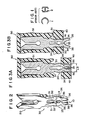
- compliant terminal 10 has "insulation displacement connection" section 20 at an upper portion and another connection section 30 at a lower portion. These sections 20 and 30 are formed integrally of conductive plate.
- Connection section 30 includes a pair of oppositely facing legs 31. At the intermediate region of the pair, portions 32 are curved outwardly. A pair of arcuate cutouts are formed on the inner surface of the intermediate region of legs 31. Each of cutouts is located on the back side of the associate expanding portion 32.
- a length La between the tops of arcuate portions 32 is greater than a diameter Lb of hole 41 of printed circuit board 40 shown in Fig. 3A.
- the arcuate portions 32 with the cutout serve as an elastic contact area 33 where they come into elastic contact with hole 41.
- Notches 34 are formed at a boundary between the intermediate region and a free end region of the leg.
- a pair of inwardly extending projections 35 are formed on the inner walls of legs 31 which correspond in level to notches 34 of legs 31. The projections 35 substantially face each other.
- Inwardly inclined tapering surfaces 36 are provided on the outer surfaces of the free end portions of the legs 31. That is, compliant terminal 10 is convergent at the lowest portions of legs 31. When legs 31 are inserted into hole 41, the end regions of legs 31 including notches 34 extend beyond the rear surface of the board.
- Compliant terminal 10 so constructed is attached to housing 51 of electric connector 50 shown in Figs. 3A and 3B.
- Electric connector 50 is attached to printed circuit board 40 by forcing legs 31 into through hole 41 with the free ends of legs 31 down. Since, in this case, the end portions of legs 31 are formed as tapering surfaces 36 it is easier to insert legs 31 along the hole 41.
- connecting section 20 can be replaced by a general female contact or others.
- the compliant terminal according to this invention assures a positive contact with the through hole of the printed circuit board and, in consequence, prevents a slippage away off a corresponding hole.
- the compliant terminal according to this inven- .tion can be obtained by merely flanking a flat-like conductive plate. It is, therefore, possible to obtain a compliant terminal which is inexpensive and compact in dimension.
Landscapes
- Coupling Device And Connection With Printed Circuit (AREA)
- Multi-Conductor Connections (AREA)
- Connector Housings Or Holding Contact Members (AREA)
- Lead Frames For Integrated Circuits (AREA)
- Electrical Discharge Machining, Electrochemical Machining, And Combined Machining (AREA)
- Processing Of Terminals (AREA)
- Connections Arranged To Contact A Plurality Of Conductors (AREA)
- Medicines Containing Plant Substances (AREA)
- Medicines Containing Material From Animals Or Micro-Organisms (AREA)
- Pharmaceuticals Containing Other Organic And Inorganic Compounds (AREA)
Applications Claiming Priority (2)
| Application Number | Priority Date | Filing Date | Title |
|---|---|---|---|
| JP1985064991U JPS61180464U (fr) | 1985-04-30 | 1985-04-30 | |
| JP64991/85U | 1985-04-30 |
Publications (3)
| Publication Number | Publication Date |
|---|---|
| EP0203638A2 true EP0203638A2 (fr) | 1986-12-03 |
| EP0203638A3 EP0203638A3 (en) | 1988-05-04 |
| EP0203638B1 EP0203638B1 (fr) | 1991-07-10 |
Family
ID=13274032
Family Applications (1)
| Application Number | Title | Priority Date | Filing Date |
|---|---|---|---|
| EP86200742A Expired - Lifetime EP0203638B1 (fr) | 1985-04-30 | 1986-04-29 | Borne adaptable |
Country Status (10)
| Country | Link |
|---|---|
| US (1) | US4676579A (fr) |
| EP (1) | EP0203638B1 (fr) |
| JP (1) | JPS61180464U (fr) |
| KR (1) | KR910009102Y1 (fr) |
| AT (1) | ATE65146T1 (fr) |
| AU (1) | AU579066B2 (fr) |
| CA (1) | CA1241400A (fr) |
| DE (1) | DE3680153D1 (fr) |
| HK (1) | HK81691A (fr) |
| SG (1) | SG80591G (fr) |
Cited By (4)
| Publication number | Priority date | Publication date | Assignee | Title |
|---|---|---|---|---|
| WO2007104500A1 (fr) * | 2006-03-12 | 2007-09-20 | Kramski Gmbh | Broche de contact et son procédé de fabrication |
| DE102006029381A1 (de) * | 2006-06-27 | 2008-01-03 | William Prym Gmbh & Co. Kg | Steckverbinder an einem Bauteil, der in einem Loch einer Basis-Platte zu befestigen ist |
| WO2010029392A1 (fr) * | 2008-09-11 | 2010-03-18 | Fci | Élément de retenue pour connecteur |
| US8632346B2 (en) | 2008-12-03 | 2014-01-21 | Wuerth Elektronik Ics Gmbh & Co. Kg | Connection assembly on circuit boards |
Families Citing this family (37)
| Publication number | Priority date | Publication date | Assignee | Title |
|---|---|---|---|---|
| US4857018A (en) * | 1988-09-01 | 1989-08-15 | Amp Incorporated | Compliant pin having improved adaptability |
| AU6402290A (en) * | 1990-09-12 | 1992-03-30 | Thomas & Betts, France | Female connector with double-strip contacts |
| AU2264192A (en) * | 1992-03-13 | 1993-10-05 | Itt Industries, Inc. | Holdown key for low profile connector |
| KR950012819A (ko) * | 1993-10-29 | 1995-05-17 | 프랭크 에이. 우울풀링 | 전기컨넥터 |
| US5478257A (en) * | 1994-04-07 | 1995-12-26 | Burndy Corporation | Retention device |
| DE19753278C1 (de) * | 1997-12-01 | 1999-07-29 | Delphi Automotive Systems Gmbh | Leiterplattenverbindungsverfahren |
| US6382988B1 (en) * | 1998-07-02 | 2002-05-07 | Ranoda Electronics Pte Ltd. | Encircled electrical compression contact |
| JP2001023715A (ja) * | 1999-07-12 | 2001-01-26 | Sumitomo Wiring Syst Ltd | 端子金具 |
| EP1187260A1 (fr) * | 2000-09-06 | 2002-03-13 | Siemens Aktiengesellschaft | Borne pour la connexion mécanique et électrique d'une plaque de circuit imprimé |
| KR100419797B1 (ko) * | 2001-07-19 | 2004-02-21 | 김동진 | 정수기 |
| US6974337B2 (en) * | 2002-07-30 | 2005-12-13 | Fci Americas Technology, Inc. | Electrical connector and contact for use therein |
| JP2005005091A (ja) * | 2003-06-11 | 2005-01-06 | Honda Tsushin Kogyo Co Ltd | 固定・接続用脚部 |
| JP4938663B2 (ja) * | 2004-06-09 | 2012-05-23 | ファイゲル アンドレアス | 圧入コンタクト |
| DE202004013708U1 (de) * | 2004-09-02 | 2004-12-23 | Abb Patent Gmbh | Verbindungselement zur Herstellung einer Verbindung zwischen Installationsschaltgeräten |
| JP4763309B2 (ja) * | 2005-02-21 | 2011-08-31 | セイコーインスツル株式会社 | 携帯型電子機器 |
| JP2007103088A (ja) * | 2005-09-30 | 2007-04-19 | Yazaki Corp | オンボードコネクタ |
| US7247050B1 (en) | 2006-10-24 | 2007-07-24 | Fci Americas Technology, Inc. | Press-fit electrical contact |
| US7399187B1 (en) * | 2007-09-20 | 2008-07-15 | Cheng Uei Precision Industry Co., Ltd. | I/O connector |
| DE102008011957B4 (de) * | 2008-03-01 | 2017-03-02 | Phoenix Contact Gmbh & Co. Kg | Schneidklemmkontakt zum abisolierfreien Anschluß |
| US7604508B1 (en) * | 2008-05-27 | 2009-10-20 | Hon Hai Precision Ind. Co., Ltd. | Electrical connector utilizing contact array |
| DE102009025113A1 (de) * | 2009-06-11 | 2010-12-16 | Continental Teves Ag & Co. Ohg | Einpresskontakt zur Verbindung eines elektronischen Bauelementes mit einer Leiterplatte sowie Einpresswerkzeug |
| DE102009042385A1 (de) * | 2009-09-21 | 2011-04-14 | Würth Elektronik Ics Gmbh & Co. Kg | Multi Fork Einpresspin |
| US8313344B2 (en) * | 2009-12-30 | 2012-11-20 | Fci Americas Technology Llc | Eye-of-the-needle mounting terminal |
| JP5494381B2 (ja) * | 2010-09-14 | 2014-05-14 | 住友電装株式会社 | コネクタ |
| JP5672211B2 (ja) * | 2011-10-24 | 2015-02-18 | トヨタ自動車株式会社 | プレスフィット端子及びコネクタ |
| JP5865743B2 (ja) * | 2012-03-16 | 2016-02-17 | 日立オートモティブシステムズ株式会社 | 端子接続部および電動アクチュエータ |
| US8900008B2 (en) * | 2012-05-25 | 2014-12-02 | International Business Machines Corporation | Universal press-fit connection for printed circuit boards |
| DE102013103818A1 (de) * | 2013-04-16 | 2014-10-30 | Walter Söhner GmbH & Co. KG | Verfahren zur Herstellung von Einpresskontakten, Einpresskontakt sowie Bauteilanordnung mit zumindest einem Einpresskontakt |
| US9083091B1 (en) * | 2013-09-06 | 2015-07-14 | Anthony Ravlich | Electrical terminal connector for solderless connection of parts to electrical contact holes |
| US9070987B2 (en) * | 2013-10-30 | 2015-06-30 | Samtec, Inc. | Connector with secure wafer retention |
| US9356367B2 (en) | 2014-01-08 | 2016-05-31 | Tyco Electronics Corporation | Electrical connector having compliant contacts and a circuit board assembly including the same |
| JP6086252B2 (ja) * | 2014-05-23 | 2017-03-01 | 株式会社オートネットワーク技術研究所 | プレスフィット端子 |
| US9276338B1 (en) | 2014-06-24 | 2016-03-01 | Emc Corporation | Compliant pin, electrical assembly including the compliant pin and method of manufacturing the compliant pin |
| EP3595417A4 (fr) * | 2017-03-06 | 2020-03-18 | Mitsubishi Electric Corporation | Unité de commande ayant une structure à ajustement par pression |
| US10276955B2 (en) * | 2017-03-31 | 2019-04-30 | Avx Corporation | Electrical connector |
| JP2021145503A (ja) * | 2020-03-13 | 2021-09-24 | 日本電産株式会社 | モータおよびモータの製造方法 |
| DE102021134576A1 (de) | 2021-12-23 | 2023-06-29 | iwis smart connect GmbH | IDC-Schneidkontakt |
Citations (3)
| Publication number | Priority date | Publication date | Assignee | Title |
|---|---|---|---|---|
| US3209309A (en) * | 1962-07-24 | 1965-09-28 | Lavoie Lab Inc | Electrical terminal board for interconnecting components |
| US3538486A (en) * | 1967-05-25 | 1970-11-03 | Amp Inc | Connector device with clamping contact means |
| DE2733229A1 (de) * | 1976-07-22 | 1978-02-02 | Nissan Motor | Klemmenstecker |
Family Cites Families (7)
| Publication number | Priority date | Publication date | Assignee | Title |
|---|---|---|---|---|
| US2329471A (en) * | 1942-08-07 | 1943-09-14 | Bell Telephone Labor Inc | Electrical terminal |
| US3717841A (en) * | 1972-05-18 | 1973-02-20 | Berg Electronics Inc | Socket terminal |
| DE2631612A1 (de) * | 1975-08-28 | 1977-04-14 | Hughes Aircraft Co | Elektrisches anschlusselement |
| US4070077A (en) * | 1976-06-01 | 1978-01-24 | E. I. Du Pont De Nemours And Company | Circuit board eyelet |
| US4384757A (en) * | 1980-12-18 | 1983-05-24 | Amp Incorporated | Terminal for connecting a ceramic chip to a printed circuit board |
| JPS57212788A (en) * | 1981-06-25 | 1982-12-27 | Oki Electric Ind Co Ltd | Method of producing pin connector with flat cable |
| US4526429A (en) * | 1983-07-26 | 1985-07-02 | Augat Inc. | Compliant pin for solderless termination to a printed wiring board |
-
1985
- 1985-04-30 JP JP1985064991U patent/JPS61180464U/ja active Pending
-
1986
- 1986-01-22 US US06/821,328 patent/US4676579A/en not_active Expired - Lifetime
- 1986-04-29 EP EP86200742A patent/EP0203638B1/fr not_active Expired - Lifetime
- 1986-04-29 CA CA000507838A patent/CA1241400A/fr not_active Expired
- 1986-04-29 AU AU56882/86A patent/AU579066B2/en not_active Ceased
- 1986-04-29 AT AT86200742T patent/ATE65146T1/de not_active IP Right Cessation
- 1986-04-29 KR KR2019860005867U patent/KR910009102Y1/ko not_active IP Right Cessation
- 1986-04-29 DE DE8686200742T patent/DE3680153D1/de not_active Expired - Lifetime
-
1991
- 1991-10-05 SG SG805/91A patent/SG80591G/en unknown
- 1991-10-17 HK HK816/91A patent/HK81691A/xx not_active IP Right Cessation
Patent Citations (3)
| Publication number | Priority date | Publication date | Assignee | Title |
|---|---|---|---|---|
| US3209309A (en) * | 1962-07-24 | 1965-09-28 | Lavoie Lab Inc | Electrical terminal board for interconnecting components |
| US3538486A (en) * | 1967-05-25 | 1970-11-03 | Amp Inc | Connector device with clamping contact means |
| DE2733229A1 (de) * | 1976-07-22 | 1978-02-02 | Nissan Motor | Klemmenstecker |
Cited By (9)
| Publication number | Priority date | Publication date | Assignee | Title |
|---|---|---|---|---|
| WO2007104500A1 (fr) * | 2006-03-12 | 2007-09-20 | Kramski Gmbh | Broche de contact et son procédé de fabrication |
| DE102006029381A1 (de) * | 2006-06-27 | 2008-01-03 | William Prym Gmbh & Co. Kg | Steckverbinder an einem Bauteil, der in einem Loch einer Basis-Platte zu befestigen ist |
| WO2008000391A1 (fr) * | 2006-06-27 | 2008-01-03 | William Prym Gmbh & Co. Kg | Connecteur enfichable sur une pièce de construction, qui doit être fixé dans un trou d'une plaque de base |
| DE102006029381B4 (de) * | 2006-06-27 | 2008-07-17 | William Prym Gmbh & Co. Kg | Steckverbinder an einem Bauteil, der in einem Loch einer Basis-Platte zu befestigen ist |
| US7713086B2 (en) | 2006-06-27 | 2010-05-11 | William Prym Gmbh & Co. Kg | Plug connector on a component which is to be fixed in a hole of a base-plate |
| WO2010029392A1 (fr) * | 2008-09-11 | 2010-03-18 | Fci | Élément de retenue pour connecteur |
| US8632346B2 (en) | 2008-12-03 | 2014-01-21 | Wuerth Elektronik Ics Gmbh & Co. Kg | Connection assembly on circuit boards |
| EP2899812A1 (fr) * | 2008-12-03 | 2015-07-29 | Würth Elektronik ICS GmbH & Co. KG | Système de connexion sur des plaques de circuit imprimé |
| EP2353208B1 (fr) * | 2008-12-03 | 2019-04-10 | Würth Elektronik ICS GmbH & Co. KG | Agencement de connexion sur des plaques conductrices |
Also Published As
| Publication number | Publication date |
|---|---|
| DE3680153D1 (de) | 1991-08-14 |
| KR860014044U (ko) | 1986-11-20 |
| HK81691A (en) | 1991-10-25 |
| CA1241400A (fr) | 1988-08-30 |
| JPS61180464U (fr) | 1986-11-11 |
| SG80591G (en) | 1991-11-15 |
| AU579066B2 (en) | 1988-11-10 |
| KR910009102Y1 (ko) | 1991-11-25 |
| EP0203638A3 (en) | 1988-05-04 |
| US4676579A (en) | 1987-06-30 |
| EP0203638B1 (fr) | 1991-07-10 |
| AU5688286A (en) | 1986-11-06 |
| ATE65146T1 (de) | 1991-07-15 |
Similar Documents
| Publication | Publication Date | Title |
|---|---|---|
| EP0203638B1 (fr) | Borne adaptable | |
| JP2533110Y2 (ja) | 接触子の過応力防止手段付き電気コネクタ | |
| US6875027B2 (en) | Electrical connector assembly with complementary recess and projection interengagement | |
| KR20000076849A (ko) | 전기커넥터 | |
| US5200884A (en) | Electrical control device | |
| KR910020968A (ko) | 저감된 피치로 배열된 수 단자 및 암 단자를 갖고 있는 보드 대 보드 전기 컨넥터 | |
| KR940016993A (ko) | 단자 정렬 시스템을 갖는 전기 커넥터 조립체 | |
| JPS5918834B2 (ja) | 接点ばね−端子盤 | |
| KR940022950A (ko) | 배터리용 콘넥터 | |
| US3523273A (en) | Electrical connectors | |
| KR920010999A (ko) | Lld 집합체 접속기 | |
| KR0117073Y1 (ko) | 접속기 | |
| US5556285A (en) | Electrical connector | |
| KR960019858A (ko) | 자체 로킹 결합 단자 구조 | |
| US4717361A (en) | Contact for connector | |
| US5879171A (en) | High density electrical connector | |
| EP0268356B1 (fr) | Douille électrique | |
| US5263867A (en) | Connector with contact locating housing part | |
| US5489219A (en) | Self-retaining board lock | |
| EP0214780A2 (fr) | Connecteur électrique | |
| US6290547B2 (en) | Receptacle for an electrical connector | |
| US4725242A (en) | Electrical connector having cam actuated wire holding means | |
| JPH05114444A (ja) | 圧入型接触子を有するコネクタ | |
| JPH0125486Y2 (fr) | ||
| JPH0152869B2 (fr) |
Legal Events
| Date | Code | Title | Description |
|---|---|---|---|
| PUAI | Public reference made under article 153(3) epc to a published international application that has entered the european phase |
Free format text: ORIGINAL CODE: 0009012 |
|
| AK | Designated contracting states |
Kind code of ref document: A2 Designated state(s): AT BE CH DE FR GB IT LI LU NL SE |
|
| PUAL | Search report despatched |
Free format text: ORIGINAL CODE: 0009013 |
|
| RHK1 | Main classification (correction) |
Ipc: H01R 9/09 |
|
| AK | Designated contracting states |
Kind code of ref document: A3 Designated state(s): AT BE CH DE FR GB IT LI LU NL SE |
|
| 17P | Request for examination filed |
Effective date: 19880921 |
|
| 17Q | First examination report despatched |
Effective date: 19900925 |
|
| GRAA | (expected) grant |
Free format text: ORIGINAL CODE: 0009210 |
|
| AK | Designated contracting states |
Kind code of ref document: B1 Designated state(s): AT BE CH DE FR GB IT LI LU NL SE |
|
| REF | Corresponds to: |
Ref document number: 65146 Country of ref document: AT Date of ref document: 19910715 Kind code of ref document: T |
|
| ITF | It: translation for a ep patent filed |
Owner name: ING. C. GREGORJ S.P.A. |
|
| ET | Fr: translation filed | ||
| REF | Corresponds to: |
Ref document number: 3680153 Country of ref document: DE Date of ref document: 19910814 |
|
| PLBE | No opposition filed within time limit |
Free format text: ORIGINAL CODE: 0009261 |
|
| STAA | Information on the status of an ep patent application or granted ep patent |
Free format text: STATUS: NO OPPOSITION FILED WITHIN TIME LIMIT |
|
| 26N | No opposition filed | ||
| PGFP | Annual fee paid to national office [announced via postgrant information from national office to epo] |
Ref country code: SE Payment date: 19930301 Year of fee payment: 8 |
|
| PGFP | Annual fee paid to national office [announced via postgrant information from national office to epo] |
Ref country code: CH Payment date: 19930302 Year of fee payment: 8 |
|
| PGFP | Annual fee paid to national office [announced via postgrant information from national office to epo] |
Ref country code: BE Payment date: 19930401 Year of fee payment: 8 |
|
| PGFP | Annual fee paid to national office [announced via postgrant information from national office to epo] |
Ref country code: LU Payment date: 19930406 Year of fee payment: 8 |
|
| PGFP | Annual fee paid to national office [announced via postgrant information from national office to epo] |
Ref country code: AT Payment date: 19930413 Year of fee payment: 8 |
|
| PGFP | Annual fee paid to national office [announced via postgrant information from national office to epo] |
Ref country code: NL Payment date: 19930430 Year of fee payment: 8 |
|
| EPTA | Lu: last paid annual fee | ||
| PG25 | Lapsed in a contracting state [announced via postgrant information from national office to epo] |
Ref country code: LU Free format text: LAPSE BECAUSE OF NON-PAYMENT OF DUE FEES Effective date: 19940429 Ref country code: AT Effective date: 19940429 |
|
| PG25 | Lapsed in a contracting state [announced via postgrant information from national office to epo] |
Ref country code: SE Effective date: 19940430 Ref country code: LI Effective date: 19940430 Ref country code: CH Effective date: 19940430 Ref country code: BE Effective date: 19940430 |
|
| BERE | Be: lapsed |
Owner name: E.I. DU PONT DE NEMOURS AND CY Effective date: 19940430 |
|
| PG25 | Lapsed in a contracting state [announced via postgrant information from national office to epo] |
Ref country code: NL Effective date: 19941101 |
|
| NLV4 | Nl: lapsed or anulled due to non-payment of the annual fee | ||
| REG | Reference to a national code |
Ref country code: CH Ref legal event code: PL |
|
| EUG | Se: european patent has lapsed |
Ref document number: 86200742.4 Effective date: 19941110 |
|
| REG | Reference to a national code |
Ref country code: GB Ref legal event code: 732E |
|
| REG | Reference to a national code |
Ref country code: FR Ref legal event code: TP |
|
| PGFP | Annual fee paid to national office [announced via postgrant information from national office to epo] |
Ref country code: GB Payment date: 20010313 Year of fee payment: 16 |
|
| PGFP | Annual fee paid to national office [announced via postgrant information from national office to epo] |
Ref country code: FR Payment date: 20010405 Year of fee payment: 16 |
|
| PGFP | Annual fee paid to national office [announced via postgrant information from national office to epo] |
Ref country code: DE Payment date: 20010430 Year of fee payment: 16 |
|
| REG | Reference to a national code |
Ref country code: GB Ref legal event code: IF02 |
|
| PG25 | Lapsed in a contracting state [announced via postgrant information from national office to epo] |
Ref country code: GB Free format text: LAPSE BECAUSE OF NON-PAYMENT OF DUE FEES Effective date: 20020429 |
|
| PG25 | Lapsed in a contracting state [announced via postgrant information from national office to epo] |
Ref country code: DE Free format text: LAPSE BECAUSE OF NON-PAYMENT OF DUE FEES Effective date: 20021101 |
|
| GBPC | Gb: european patent ceased through non-payment of renewal fee |
Effective date: 20020429 |
|
| PG25 | Lapsed in a contracting state [announced via postgrant information from national office to epo] |
Ref country code: FR Free format text: LAPSE BECAUSE OF NON-PAYMENT OF DUE FEES Effective date: 20021231 |
|
| REG | Reference to a national code |
Ref country code: FR Ref legal event code: ST |
|
| PG25 | Lapsed in a contracting state [announced via postgrant information from national office to epo] |
Ref country code: IT Free format text: LAPSE BECAUSE OF NON-PAYMENT OF DUE FEES;WARNING: LAPSES OF ITALIAN PATENTS WITH EFFECTIVE DATE BEFORE 2007 MAY HAVE OCCURRED AT ANY TIME BEFORE 2007. THE CORRECT EFFECTIVE DATE MAY BE DIFFERENT FROM THE ONE RECORDED. Effective date: 20050429 |