EP0203269A2 - Accessoire de câble fileté - Google Patents
Accessoire de câble fileté Download PDFInfo
- Publication number
- EP0203269A2 EP0203269A2 EP86102384A EP86102384A EP0203269A2 EP 0203269 A2 EP0203269 A2 EP 0203269A2 EP 86102384 A EP86102384 A EP 86102384A EP 86102384 A EP86102384 A EP 86102384A EP 0203269 A2 EP0203269 A2 EP 0203269A2
- Authority
- EP
- European Patent Office
- Prior art keywords
- clamping
- sleeve
- insert
- cable
- cable gland
- Prior art date
- Legal status (The legal status is an assumption and is not a legal conclusion. Google has not performed a legal analysis and makes no representation as to the accuracy of the status listed.)
- Granted
Links
Images


Classifications
-
- H—ELECTRICITY
- H02—GENERATION; CONVERSION OR DISTRIBUTION OF ELECTRIC POWER
- H02G—INSTALLATION OF ELECTRIC CABLES OR LINES, OR OF COMBINED OPTICAL AND ELECTRIC CABLES OR LINES
- H02G3/00—Installations of electric cables or lines or protective tubing therefor in or on buildings, equivalent structures or vehicles
- H02G3/02—Details
- H02G3/06—Joints for connecting lengths of protective tubing or channels, to each other or to casings, e.g. to distribution boxes; Ensuring electrical continuity in the joint
- H02G3/0616—Joints for connecting tubing to casing
- H02G3/0625—Joints for connecting tubing to casing with means for preventing disengagement of conductors
- H02G3/0675—Joints for connecting tubing to casing with means for preventing disengagement of conductors with bolts operating in a direction parallel to the conductors
-
- H—ELECTRICITY
- H02—GENERATION; CONVERSION OR DISTRIBUTION OF ELECTRIC POWER
- H02G—INSTALLATION OF ELECTRIC CABLES OR LINES, OR OF COMBINED OPTICAL AND ELECTRIC CABLES OR LINES
- H02G3/00—Installations of electric cables or lines or protective tubing therefor in or on buildings, equivalent structures or vehicles
- H02G3/02—Details
- H02G3/06—Joints for connecting lengths of protective tubing or channels, to each other or to casings, e.g. to distribution boxes; Ensuring electrical continuity in the joint
- H02G3/0616—Joints for connecting tubing to casing
- H02G3/0625—Joints for connecting tubing to casing with means for preventing disengagement of conductors
- H02G3/065—Joints for connecting tubing to casing with means for preventing disengagement of conductors with means biting into the conductor-insulation, e.g. teeth-like elements or gripping fingers
-
- H—ELECTRICITY
- H02—GENERATION; CONVERSION OR DISTRIBUTION OF ELECTRIC POWER
- H02G—INSTALLATION OF ELECTRIC CABLES OR LINES, OR OF COMBINED OPTICAL AND ELECTRIC CABLES OR LINES
- H02G3/00—Installations of electric cables or lines or protective tubing therefor in or on buildings, equivalent structures or vehicles
- H02G3/02—Details
- H02G3/06—Joints for connecting lengths of protective tubing or channels, to each other or to casings, e.g. to distribution boxes; Ensuring electrical continuity in the joint
- H02G3/0616—Joints for connecting tubing to casing
- H02G3/0625—Joints for connecting tubing to casing with means for preventing disengagement of conductors
- H02G3/0658—Joints for connecting tubing to casing with means for preventing disengagement of conductors with means constricting the conductor-insulation
Definitions
- the invention relates to a cable gland with a screw sleeve, a mating sleeve which can be connected thereto, preferably by means of a thread, and a clamping insert which can be pressed therewith or thereby against the cable or a protective tube, preferably made of harder material than the cable sheath, the mating sleeve or the like having the clamping insert on the outside overlaps an annular surface at least on the end face and preferably with a tapering shape when tightening the connection or thread.
- a region of the clamping insert provided with axial, at the end opening slots radially deformed towards the cable, fixes the cable and seals it indirectly or directly.
- Cable glands serve e.g. B. for inserting cables into machines, control cabinets or the like. Or for implementation through walls and are known in various designs and embodiments. These cable glands are intended to securely seal and secure the cable, whereby in usually a cable clamp is caused by the connection of the screw sleeve with the counter sleeve. By axially moving these two sleeves against each other, in particular by screwing the parts together, the clamping insert is radially compressed due to its slots, so that it lies around the cable, constricts it, clamps it and also seals it.
- the clamping insert generally consists of an elastic plastic which is harder than the cable sheath or a sealing insert and has the slots mentioned at the beginning to increase its elasticity. These clamping inserts also have a tendency to lose their shape and internal stress under pressure, so that the clamping effect diminishes and the strain relief for the cable is lost.
- DE-PS 31 22 388 a screwed cable gland of the type mentioned is known, in which the counter sleeve acts on a clamping insert which, when the thread of the two screwable sleeves is tightened, on the one hand acts on the cable material and clamps onto it, while the other end face of this clamping insert is pressed at a distance from the cable against a sealing insert made of softer material in the screw sleeve.
- DE-PS 31 22 388 shows in the illustrated embodiment in the representation of this cable gland in the use position clearly how the sealing material of the sealing insert is deformed from the outset in a direction in which it can crawl away over time. Due to the arched shape of the sealing insert, even with a slight reduction in stress in this sealing insert due to material fatigue or by the material creeping away a deteriorating sealing effect.
- a screwed cable gland with a strain relief in which a clamping insert with alternately open on one and the opposite side, overlapping slots on the outside is surrounded by a sealing sleeve, which the clamping pressure must be transferred from the screw sleeve and the counter sleeve screwable with it.
- the edges of the sealing sleeve can creep into the gap between the cable and the cable gland over time, which is kept open by the clamping insert.
- the sealing sleeve is subjected to an unfavorable load from the outset because it has an integrally formed ring on its circumference, which is fixed in a groove in the screw sleeve and sheared off by the axial loading.
- the solution to this problem consists essentially in the fact that at least two at least radially flexible clamping inserts are provided, the clamping areas of which are axially aligned Hold the cable or hose next to one another and have a cavity between them.
- This cavity between the two clamping areas can accommodate a bulge formed by the constrictions of the cable or hose.
- the two spaced-apart clamping points not only produce an improved clamping effect, but also form-fitting connection effective in both directions of orientation of the cable.
- the bulge is chambered between the clamping points and thus the soft material is prevented from crawling away in one or the other or both directions. There is no gap or opening for this.
- the two clamping inserts have flat or inside and outside conical end faces on their mutually facing end faces, which over the outer end faces of pressurized inner cones of the screw or counter sleeve for radially compressing their slotted regions when the counter sleeve is tightened in the axial direction and compressible in the radial direction.
- a particularly simple and expedient embodiment of the invention can consist in that the two clamping inserts are connected in one piece. This simplifies, above all, the production and also the assembly of these clamping inserts, because they are connected to a single part, which can have the cavity in its interior for receiving the bulge formed by the constrictions.
- the slots on both sides of these one-piece clamping inserts which are open towards the end in each case towards the edge, can each extend in the axial direction over half of the clamping insert into the other half, so that the closed end regions of the slots overlap.
- the two clamping points of such a double clamping insert can be deformed correspondingly well in the radial direction in order to constrict the cable and to form a bulge between the clamping points.
- the integrally connected clamping inserts can have a support against the inside of the screw sleeve and / or the counter sleeve, in particular approximately in their common center.
- an approximately annular projection with an external thread can be provided as a support on the clamping insert, which matches the internal thread of the mating sleeve overlapping an external thread of the screw sleeve and is gripped and acted upon by the internal thread of the mating sleeve when the screw connection is tightened.
- the clamping inserts connected in one piece to form a double clamping insert are not only grasped on the conical end faces for the deformation in the radial direction, but are also held in a form-fitting manner in the common central region approximately radially outside the cavity between the clamping points and secured against tilting, so that the clamping forces can be generated evenly at both clamping points.
- An embodiment of the invention of very considerable loading Interpretation in particular for the improvement of the sealing effect of the cable gland can consist in that at least one sealing ring is included in the cavity facing the cable or hose between two clamping points of the clamping inserts - or the one-piece double clamping insert - and that - the two end faces or end faces of the Sealing ring at least in the use or clamping position are completely overlapped by the clamping areas of the clamping insert (s).
- the cavity between the clamping points accommodates a sealing ring which, due to the clamping forces and the resulting bulge of the cable as well as the radial compression of the clamping insert (s), generates a large sealing force without the sealing material being able to creep away because of the clamping points located on both sides of it are completely enclosed.
- the cable or the hose can nevertheless bulge out a little or be restricted to such a deformation, but then a corresponding clamping effect also arises in the region of the cavity between the sealing material and the cable or hose.
- a seal is arranged in the axial direction next to the one or more clamping inserts, which seal can be compressed by tightening the counter sleeve by the clamping inserts.
- a connecting sleeve can be arranged between the clamping inserts and the sealing insert arranged axially next to it, which is provided and designed on the side facing the clamping inserts for deforming the same, for example has a cone, and has a connection for the counter sleeve, while the axially opposite lying side serves to deform the seal and has a connection for the screw sleeve, so that the clamping inserts and the seal can be deformed independently of one another. This means that it is up to the user to regulate and adjust the clamping effect and the sealing effect independently of one another.
- Another embodiment of the invention can consist in that the two, which maintain a spacing from one another and bulge of the cable and / or a cavity arranged there between the clamping inserts, are separated from one another and on the mutually facing end faces one by screwing the screw sleeve and Have counter sleeve reducible or closable distance and / or overlap telescopically and displaceable relative to each other.
- the two clamping inserts can first be deformed and acted upon independently of one another, so that the risk of tipping or jamming is reduced or eliminated.
- At least one clamping insert is provided with a flat slope on its outside, which drops at an acute angle from the largest diameter towards the cable surface, the inclination of the slope being directed towards the opening of the counter sleeve is and on the outside of this slope another, interacting with the counter sleeve clamping insert acts indirectly or directly.
- the sloping slope is oriented in the direction in which tensile loads on the cable are generally to be expected.
- this second clamping insert also fulfills the purpose; to effect a self-locking strain relief due to this acute-angled bevel. If the cable is pulled in the direction in which the outside of this clamping insert drops at an acute angle, this clamping insert, which is already clamped against the cable surface, wants to follow this movement and is therefore pressed against the cable surface accordingly more strongly.
- the clamping points according to the invention for constricting the cable, a good seal and a combine automatic strain relief if an additional radially flexible insert with axial slots on both sides and an acute-angled self-locking cone on the outside is provided as additional strain relief in the interior of the seal acted upon by the two clamping inserts leaving a cavity between the clamping inserts that are left free. It is again advantageous that the two clamping inserts according to the invention are at a distance from one another and leave a cavity between them, in which the aforementioned seal and this additional acute-angled clamping insert can be accommodated.
- the invention further allows further configurations in which, for example, the clamping insert or inserts according to the invention are integrally connected to the screw sleeve or the counter sleeve, if these consist of plastic.
- the number of clamping points can also be larger and, for example, at least three clamping points can be provided, the two of which have a preferably free cavity between them, while between these two clamping points and a third clamping point there is a further cavity with a seal arranged therein.
- a bulge of the cable can then be well combed in the free space, while a seal can be enclosed in the second cavity to prevent it from creeping away.
- a cable gland with two clamping inserts or clamping points which can also be connected to form a one-piece clamping insert and has a chambered seal between the clamping points, can have an independently protective design in such a way that this chambered and arranged seal between two clamping inserts or clamping points, at least when the screw connection is tightened with one of its front ends on the outside of at least one of the clamping inserts is slidable and deformed this clamping insert radially against the cable.
- This achieves the advantages of the invention and additionally improves the sealing effect.
- the area of the seal that is pushed over a clamping insert can certainly not crawl away even under pressure, because it is, so to speak, inserted into a "dead end".
- this seal then seals the clamping insert, which it overlaps on the outside, well, because it is pressed so tightly due to the special arrangement and function that this clamping insert is in turn pressed against the cable. Since the opposite edge of the seal is in turn overlapped laterally by the other clamping insert by its clamping point, this sealing insert can, so to speak, pass between the two clamping inserts from the inside to the outside and thus also provide a good seal in this area.
- the seal can rest on at least one of the clamping inserts with an area on the outside before the screw connection is tightened. It is particularly expedient if the seal acts on the outside of the second clamping insert facing away from the counter sleeve inside the screw sleeve and can be pushed onto it, which then causes the counter sleeve in a simple manner when it is tightened can be. The axial movement of the counter sleeve then continues in a corresponding axial movement of the directional insert.
- An embodiment of this embodiment of the invention can consist in that the seal also engages over the clamping insert gripped by the counter sleeve when screwing on the outside thereof and presses radially against the cable.
- Embodiments of the clamping inserts, in particular on their end faces, for interacting with seals arranged between them and also the screw sleeve and the counter sleeve are the subject of claims 33 to 37.
- the entire .cable screw connection and in particular the maintenance of its effect even over long years by avoiding creeping soft materials can be improved in that the inside of the screw sleeve on the end face facing away from the counter sleeve. side of the clamping insert, a counter pressure ring is provided for radially deforming the slotted region of the clamping insert facing it and / or a sealing insert.
- a shoulder with or without undercut of the inner wall is provided in the counter sleeve, on which the pressure ring rests immediately or only in the course of the axial displacement of the shoulder, which in a correspondingly shaped outer groove of the unilaterally connected clamping inserts, which in an undercut, if any, protrude, preferably having axial slots on one side, engages and the integrally connected clamping inserts are deformed in the radial direction when the counter-sleeve is screwed on in cooperation with the pressure cone of the counter-sleeve, the clamping points being different designed pressure areas are compressible in parallel and both clamping points are placed around the cable at the same time.
- the two integrally connected clamping inserts can also be integrally formed on the screw sleeve.
- the counterpressure ring can act on an axially adjoining seal, in particular if it is arranged in the screw sleeve, with its end face facing away from the clamping insert and deform it when the counter sleeve is tightened into the sealing position.
- the counter pressure ring can overlap the seal on the outside and thereby shield and protect against the thread of the sleeve.
- the counter pressure ring can be slotted and at the same time radially deformable under the action of an inclined surface against an area of the sealing ring which it partially overlaps.
- the counter pressure ring acts like a clamping insert acting on the sealing ring.
- the invention first of all ensures that, with an improved clamping effect within the cable gland, the forces occurring on a cable or hose can be better absorbed due to two clamping points arranged at a distance from one another. At the same time, this creates a constriction that prevents the clamped material from creeping away and thus prevents the clamp connection from loosening over the years.
- the sealing effect can be improved by either chambering the constricted bulge itself or a gasket combined with it, the material of which is also prevented from creeping away.
- the clamping and sealing forces and effects can be increased and even a configuration is possible which automatically increases the clamping effect, especially when the cable is subjected to tensile stress.
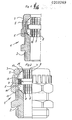
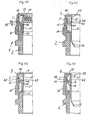
- the cable glands 1 shown have in common that they each have a screw sleeve 2 and a mating sleeve 3 that can be connected by means of a thread, either a union nut - as in most of the cases shown - or a screw-in socket.
- a thread either a union nut - as in most of the cases shown - or a screw-in socket.
- the cable gland 1 is fixed to the cable 6 or, conversely, the cable 6 in the cable gland 1.
- the mating sleeve 3 overlaps a clamping insert 5 on the outside and with an annular surface 15 on the end face, this annular surface being designed as a cone, so that the clamping insert 5 yields due to slots 7 opening on its end face and is radially deformed towards the cable 6.
- At least two radially flexible clamping inserts 5 are provided, the clamping regions 8 of which engage axially at a distance from one another on the cable 6 or a hose and have a cavity 9 between them.
- This cavity 9 can accommodate a bulge 11 of the cable 6 or the hose surface formed by the constrictions 10 on the clamping areas 8, as is indicated, for example, in FIGS. 36 or 44 and 45, 48 and 50.
- Such a cable gland 1 remains correspondingly longer.
- a seal and / or a further clamping insert can also be provided in the cavity 9 in a manner to be described later in order to further improve the clamping effect and the sealing effect.
- the two clamping inserts 5 can have flat end faces 12 on their mutually facing end faces. Also in Fig. 4 it can be seen that the end faces of the two clamping inserts touching one another in the use position are flat, this plane as in Fig. 2 and also in other comparable figures, for example 11, are arranged in a cross-sectional plane perpendicular to the longitudinal axis of the cable gland 1.
- FIG. 3 A modification can be seen in FIG. 3, in which the contacting end faces 12 are arranged conically, the inclination of these end faces corresponding to one another in such a way that both end faces in turn lie against one another.
- each other end faces 13 are also arranged obliquely, with the majority of the embodiments, the slope from the larger outer diameter to the smaller outer diameter, so that the clamping inserts have a greater length on their inner diameter than on their outer diameter.
- These outer end faces 13 are acted upon by inner cones 14 and 15 of the screw sleeve 2 and the counter sleeve 3 and serve for the radial compression of their slots 7 when the counter sleeve 3 is tightened in the axial direction.
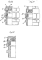
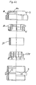
- FIGS. 35 and 37 are examples of the fact that the slots 7 of the integrally connected clamping inserts 5 on both sides, each of which is open towards the edge towards an outer end face 13, extend in the axial direction over half of the clamping insert 5 and into the other half , so that the closed end regions of the slots 7 overlap each other.
- such a one-piece clamping insert with two clamping points can yield radially and produce the desired constrictions 11 with its clamping points 8.
- the integrally connected clamping inserts 5 can have a support 16 opposite the inside of the screw sleeve 2 and / or the counter sleeve 3, which is preferably arranged approximately in its common center. Examples of this are the embodiments according to. 5 or 15.
- Fig. 5 shows a solution in which an approximately annular projection with an external thread is provided as a support 16 on the clamping insert 5, which matches the internal thread of the mating sleeve 3 spanning an external thread of the screw sleeve 2 and when the screw connection is tightened by the internal thread the counter sleeve 3 is detected and acted upon. .
- this clamping insert 5 cannot be tilted and tilted. Accordingly, both clamping points 8 come into the use position.
- Fig. 15 shows a solution in which a radially on the outside support collar is provided as a support 16 of the integrally connected clamping inserts 5, which is connected to the clamping insert 5 via a radially projecting ring or web 17 and laterally this Ver Binding compared to the clamping insert 5 has an annular distance 18, in which the end face 19 of the screw sleeve 2 partially engages.
- This end face 19 of the screw sleeve 2 which engages in the annular spacing 18 under the support collar of the support 16, is in this. sem case formed approximately knife-shaped and thickened conically, so that it causes even greater jamming and support when tightened more.
- the inner annular surface 15 - as the inner cone - of the counter sleeve 3 and the counter surface interacting with it via the clamping inserts 5 - also an inner cone 14 '- of the screw sleeve 2, between which surfaces 14 and 15 the two individual ones Pieces or one-piece clamping inserts 5 are arranged, from the outside to the inside so inclined or conical or also curved or rounded that they have a greater distance from each other in their interior near their central axis than on their outer diameters and that the clamping inserts 5 on their with these conical annular surfaces 14 and 15 cooperating end faces 13 are also beveled and additionally slotted.
- slots 7 of the clamping inserts 5 which extend in the axial direction and are open at the end, can also run obliquely in the radial direction, while according to FIGS. 6 and 8 they can also run directly in the radial direction.
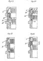
- FIGS. 5 to 9 show an embodiment that before is all advantageous for improving the sealing effect.
- the slots 7 can namely be closed by a thin, flexible skin 20. It can be seen in FIGS. 6 and 7 in connection with FIG. 5 that the slots 7 of the clamping inserts 5 in the area of the counter sleeve 3 are closed on the inside with the skin 20.
- FIGS. 8 and 9 again show in connection with FIG. 5 that the slots of the second clamping insert or the second clamping point in the area of the screw sleeve 2 are closed on the outside with the skin 20.
- a so designed and combined one-piece clamping insert 5 with two clamping points 8 simultaneously provides a good seal, which can be improved by slots 7 which run obliquely to the radius, as shown in FIGS.
- the support 16 acting as a sealing collar is located between the two partially slotted regions of the clamping insert 5 according to FIG. 5 and has the double function mentioned, to act simultaneously as a support and in FIG. 15 as a seal on the inside of the screw sleeve 2 and the counter sleeve 3.
- a cable gland designed in this way with a one-piece clamping insert 5 with support 16 serving as a sealing collar and slots 7 closed off by a skin 20 can not only effect a good jamming of the cable 6, but also a good seal at the same time.
- a sealing ring 21 is enclosed or arranged in the cavity 9 or intermediate space facing the cable 6 or hose between two clamping points 8 of the clamping inserts 5 and that the two end faces or end faces 22 of the sealing ring 21 are at least in the use position or Clamping position is overlapped by the clamping areas 8 of the clamping insert (s) 5.
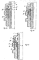
- FIGS. 13 and 14 An example of this can be seen in the embodiment according to FIGS. 13 and 14. In FIG. 13 the screwed cable gland can be seen before being fixed, in FIG. 14 in the use position.
- FIG. 19 Another example of a sealing ring 21 chambered between two clamping points is shown in FIG. 19, in which, as an additional special feature, not only two integrally connected clamping inserts, .soriders are provided in a manner to be described, a third clamping insert.
- FIGS. 58 to 66 show further examples of a sealing ring 21 chambered between two clamping points 8, additional measures for. Fixation of the sealing ring, which will be described in the explanation of these figures.
- the spaced-apart clamping points of the clamping insert or inserts not only improve the fixation and chambering of the bulged hose material, but if necessary additionally chambering a sealing ring in such a way that its material is not in the Can creep away over the years due to the pressure.
- FIGS. 69 to 76 Further examples with chambered seals are the embodiments according to FIGS. 69 to 76, the sealing rings 21 being able to have further configurations in a manner to be described. Further sealing options with a seal 21 engaging in the cavity between the two clamping points can be seen from FIGS. 12 or 24 and 25, 47 and 48, 51 and 55 to 57.
- a further or additional possibility of improving the seal can consist in that a seal 23 can be arranged in the axial direction next to the clamping inserts 5, be they made of two parts or in one piece, which can be compressed by the clamping insert 5 by tightening the counter sleeve 3.
- Such a sealing arrangement is indicated, for example, in FIGS. 10, 17, 18, 19 and 47 to 57, in some cases a combination of such a sealing ring located axially next to the clamping insert 5 with two clamping points 8 with a sealing insert 21 - z.
- B. in Fig. 48 or Fig. 16 is provided in a manner to be described.
- FIGS. 11, 26 and 27 show a cable screw connection 1, in which a connecting sleeve 24 is arranged between the clamping inserts 5 and the sealing insert 23 arranged axially next to it, which serves to deform the clamping inserts 5 and a corresponding inner cone 14 and also has a connection, in particular a thread for the counter sleeve 3, while the axially opposite side serves to deform the seal and has a connection for the screw sleeve 2, so that the clamping inserts 5 and the seal 23 are deformable independently of one another.
- the counter sleeve 3 can either be a union nut or a screw-in socket.
- the seal 21 between the clamping inserts 5 or their clamping points 8 and the cable 6 or hose is arranged or axially adjacent area of the clamping insert 5 on the inside of the screw sleeve 2 - z. B. at 14 or 31 - and is guided through the clamping insert 5 through one or more clamping points 8, so that the seal between the cable 6 and the clamping point 8 clamped prevents damage to the cable surface by the clamping insert at this point 8. Examples of this are FIGS. 12 with a seal 21 located in the cavity 9 and two lateral extensions 25 for shielding the clamping points 8, FIG.
- FIGS. 47 and 48 projecting under both clamping points, which largely corresponds to the embodiment according to FIG. 16 with regard to the seal 23 and its continuation 25, FIGS. 49 and 50, in which the continuation 25 of the sealing ring 23 only below the immediately adjacent clamping point 8, and FIGS. 51 and 55 to 57, in which the sealing ring 23 and its extension 25 have practically a constant thickness.
- the sealing insert 21 or 23 has, at least on one end face, a step-like offset which merges into the aforementioned continuation 25 and, as mentioned, overlaps at least one clamping point 8 of the clamping insert 5 , so that the cable surface cannot be damaged at this point by the clamping insert 5 and nevertheless the sealing insert 21 or 23 withstands better through this chambering when the cable 6 is under tensile load.
- a step-like offset which merges into the aforementioned continuation 25 and, as mentioned, overlaps at least one clamping point 8 of the clamping insert 5 , so that the cable surface cannot be damaged at this point by the clamping insert 5 and nevertheless the sealing insert 21 or 23 withstands better through this chambering when the cable 6 is under tensile load.
- the end of the sealing insert 21 or 23 which is directed completely or partially through the clamping points 8 and which faces away from the counter sleeve 3 can be designed and extended as a sealing lip 26 directed against the cable 6 or the hose, wherein this applies in particular to FIGS. 55 to 57 and 73 to 76, while according to FIG. 61 at least one clamping insert 5 can receive and clamp a sealing lip 26 between its end face and the sleeve 2 acting on it.
- This sealing lip 26 represents an improvement in the seal, but also the insulation.
- FIGS. 12 to 14 and 71 and 72 already mentioned in another context also show an embodiment of the cable gland 1 according to the invention, according to which the two maintaining a distance from each other and a bulge 11 of the cable 6 and / or a cavity 21 arranged there receiving cavity 9 between the clamping inserts 5 are separated from each other and on the facing end faces 12 a reducible by screwing the screw sleeve 2 and the counter sleeve 3 or even closable distance, they can even overlap telescopically and displaceable relative to each other according to FIGS. 12 and 71 and 72.
- Each clamping insert 5 is thus initially acted upon separately and compressed radially, but at the same time is also displaced in the axial direction towards the other or even guided on the other during this displacement movement.
- a clamping insert with a flat slope on the outside is provided, which either forms one of the clamping inserts 5 or is additionally provided as a further clamping insert and in the exemplary embodiments which show such a clamping insert with a flat slope on the outside, as a clamping insert 28 is designated.
- the flat beveled outside 29 of this clamping insert 28 drops at an acute angle from the largest diameter towards the cable surface, the inclination of the bevel of the outside 29 is directed towards the opening 30a of the counter sleeve 3, so that there is a pull the cable acted upon by this clamping insert 28, this clamping insert 28 would like to follow the cable, but is then pressed all the more against the cable due to the flat slope. Because of its external shape, this clamping insert 28 forms a self-locking strain relief insert.
- This clamping insert 28 can interact directly or indirectly with the counter sleeve 3 and / or the screw sleeve 2.
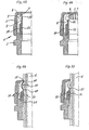
- Such a "self-locking" clamping insert 28 is provided, for example, in FIGS. 20 to 23, but also in FIGS. 59 to 65 - in the latter as one of the two clamping inserts 5.
- FIGS. 69 to 76 inside the seal 21 acted upon by the two a cavity 9 between the clamping inserts 5 that are left free or, for example according to FIGS. 41, 43, 46 and 22, such an additional radially flexible, bilateral can be provided in at least one of the clamping inserts 5 insert 28 provided with axial slots 7 with an acute-angled self-locking cone on the outside 29 can be provided as additional strain relief.
- This strain relief insert 28 can be provided with one (e.g. FIGS. 38, 69, 70, 71, 41) or two (FIG. 73) flat bevels or curves (FIGS. 72 and 74) on its outside 29, which is in a clamping insert or in the sealing insert 21. In the case of two flat bevels or corresponding roundings which drop approximately evenly on both sides, this strain relief insert 28 can act automatically or self-locking in the case of tensile forces in both directions on the cable 6.
- strain relief insert 29 is encompassed by a clamping insert 5
- this can have slots which are offset on both sides and overlap in the axial direction and allow the two inserts to be pressed together in parallel. This prevents one-sided clamping and the self-locking shape of the strain relief insert 28 is maintained and effective,
- the self-locking strain relief insert 28 on its side facing the cable or hose surface and for Holding the cable 6 or the hose arbitrarily shaped, preferably toothed.
- Inner wall can have a cavity 27 located between two clamping points, which in turn allows the cable or hose surface to bulge according to the invention when the cable is constricted, absorbs it and becomes increasingly stronger under tensile load encloses.
- the strain relief insert 28 can thus be viewed practically as the two integrally connected clamping inserts 5 according to the invention, but a further clamping insert on the outside of this strain relief insert 28 or a compressible seal is also effective.
- the cable gland 1 can be at least partially made of plastic and at least one clamping insert 5 can be integrally formed on the screw sleeve 2 and / or the counter sleeve 3.
- An embodiment of this idea is shown in Fig. 58.
- the screw sleeve 2 is made of plastic and an annular area of the screw sleeve 2 facing the counter sleeve 3 is formed as a single piece with this clamping insert 5 and is provided with slots 7 and for a radial deformation of this slotted area inwards a conical end area for Cooperation with the counter sleeve 2 or a region of the second clamping insert 5 acted upon by the counter sleeve 2 -
- these effects are only indirect in the exemplary embodiment in each case - or, as provided in the exemplary embodiment, for interaction with the sealing ring 21.
- the two clamping inserts 5, which are arranged at a distance from one another, are also in the screwed and clamping position on the mutually facing end faces 12 - for example in contrast to the embodiment of FIG. 2 or 12 - then keep a reduced distance into which the sealing ring 21 compressed and deformed by the screwing protrudes radially outward due to its compression and deformation and seals the entire cross section.
- Fig. 66 is an example of the fact that in a production of the screw sleeve 2 and the counter sleeve 3 made of plastic each of these parts, a clamping insert 5 can be integrally formed, but these clamping inserts are loosely inserted and clamped in corresponding embodiments of the sleeves in these embodiments could.
- At least three clamping points 8 can be provided, the two of which have the free space or a seal or the like which holds a cavity 9 between them, while a cavity with between these two clamping points and the at least third clamping point a seal 23 arranged therein can be provided.
- 43 is a further example of this, in which the clamping points arranged on both sides of the sealing ring 23 in turn have a self-locking relief insert 28 in the cavity.
- a further clamping insert 28 is arranged between the two clamping points forming a cavity, but which leaves two partial cavities 8a between them and the two clamping points 8, which leads to good fastening according to Fig. 36 leads.
- the seal 21 arranged and chambered between two clamping inserts 5 or clamping points 8 can be pushed onto the outside of at least one of the clamping inserts 5 with at least one of its front ends, at least when the screw connection 1 is tightened deformed this clamping insert radially against the cable. At least this edge area of the seal pushed onto the clamping insert is certainly not exposed to the risk of crawling away. In this case, the seal can rest on at least one of the clamping inserts on the outside of this end region before the screw connection is tightened.
- Fig. 65 is an example where the seal rests with both edge areas on the outside of both clamping inserts.
- the examples according to FIGS. 58 to 61 show that the seal 21 acts on the outside of the second clamping insert 5 facing away from the counter sleeve 3 and can be slidable thereon.
- the seal 21 also engages over the clamping insert 5, which is gripped by the counter sleeve 3 or even connected to it, when it is screwed on the outside thereof and presses radially against the cable 6.
- the two clamping inserts 5 to each other have opposite end faces 12 facing away from each other, on each of which an end face of the seal 21 arranged between these two clamping inserts 5 engages and slides on when tightening the mating sleeve 3, thereby also deforming the clamping inserts 5 both radially against the cable 6.
- Fig. 60 it can still be seen that the clamping insert 5 arranged in the screw sleeve 2 has a continuation 30 lining the inner wall of the screw sleeve 2, so that this clamping insert 5 has an additional function. in particular by additionally isolating a screw sleeve made of metal.
- FIGS. 59 to 65 also show that the screw sleeve 2, which may be made of metal, may have a radial or oblique shoulder 31 (FIGS. 61 to 65) or a radial or oblique annular groove 32 (FIGS. 59 and 60, possibly 61) one of the clamping inserts 5 is supported and / or locked in place with an end face facing away from its clamping point 8.
- the screw sleeve 2 which may be made of metal, may have a radial or oblique shoulder 31 (FIGS. 61 to 65) or a radial or oblique annular groove 32 (FIGS. 59 and 60, possibly 61) one of the clamping inserts 5 is supported and / or locked in place with an end face facing away from its clamping point 8.
- FIGS. 58 to 61 also show an embodiment, in particular, of the counter sleeve, according to which the screwable counter sleeve 3 in the region of its end conical ring surface 15 has a free rotation 33 of its internal thread and the clamping insert 5 provided at this point has a one-piece outer ring which projects into this free rotation 33 34 is.
- the end face annular surface 15 of the counter sleeve 3 extends conically obliquely in the region of the free rotation 33 to the bottom thereof, so that the clamping insert is also acted on its outer ring 34 in the sense of a pinch when the counter sleeve 3 is screwed onto the screw sleeve 2.
- the round cross-section of the outer ring leaves a certain rolling movement of the clamping insert in its radial deformation.
- the interaction of the clamping inserts 5 with the screw sleeve 2 can, depending on the design of the clamping inserts 5 or also these adjacent seals 23, be improved with or without further clamping inserts in that a counter pressure ring 35 inside the screw sleeve 2 on the end face 13 of the clamping insert 5 facing away from the counter sleeve for radially deforming the slotted region of the clamping insert 5 facing it (for example in the embodiment according to FIGS. 52 and 53 or 37 and 39) and / or a sealing insert (for example according to FIG. 37).
- the counter pressure ring 35 acts with its end facing away from the clamping insert 5 on an axially adjoining seal 23 and deforms it when the counter sleeve 3 is tightened into its sealing position, as is shown, for example, in FIGS. 18, 37 or 39 and also in FIGS. 44 and 45 is shown in the use position.
- the counter pressure ring 35 overlaps the seal 23 on the outside thereof with a sleeve-like extension 36 and thereby shields against the thread of the counter sleeve 3.
- FIGS. 40 to 43 show further examples of counter pressure rings 35.
- the counter pressure ring 35 is slotted and at the same time radially deformable under the action of an inclined surface 37, preferably on the screw sleeve 2, against an area of the sealing ring 23 which it partially engages is.
- it forms the sealing ring 23 on the front side and in the edge area on the outside encompassing and thus chambering counter pressure ring 35 practically another clamping insert, which improves the sealing effect and makes it difficult or creeping away of the sealing material. avoids.
- the sealing ring 35 is chambered and clamped in this case.
- FIGS. 47 to 50 and to a certain extent also in FIGS. 74 and 54 and in a modified form in FIGS. 52 and 53 it is provided that the clamping inserts 5, which are optionally connected in one piece or also separately, are continued as a continuation of the inner screw sleeve side Clamping insert 5 arranged sealing ring 23 is overlapped on its outside by an outer continuation 38 of the clamping insert 5 and is shielded from the threaded area of the cable gland 1, this continuation 38 possibly also being integrally connected to the screw sleeve 2.
- the special feature of FIGS. 52 and 53 is that this continuation is not directly connected to the clamping inserts 5, that is to say it continues only in the figurative sense or indirectly.
- the sleeve and the counter sleeve are designed as two practically facing rings, which can be brought together by axial screws 4 and thereby jammed.
- an outer ring 40 sits in one piece on a threaded shoulder 42, while an axially movable intermediate ring 43 is arranged between these two parts, which can be inserted through the spaces between the connecting webs 44, especially since it is interrupted at its circumference according to FIGS. 30 and 31 and is held together by one of the screws 4 at its interruption in the use position. If the screws 4 are tightened, the ring 43 is pulled against the ring 40, so that the inner cones of the two rings 40 and 43 act in the same way on the clamping inserts 5, as is the case when the screw sleeve 2 cooperates with the counter sleeve 3 in the other exemplary embodiments the case is.
- the corresponding clamping position is shown in Fig. 36. It can be seen there that the screw attachment 42 can in turn engage in a further sleeve 45 with an axially adjacent sealing ring 23 in order to improve the sealing of this cable gland accordingly.
- a self-locking clamping insert 28 can also be arranged inside the sealing ring 23. This is also possible with other such sealing rings 23 in other exemplary embodiments.
- an additional pressure ring could also be provided in one case or another.
- FIGS. 24, 25 and 54 to 57 which serve primarily to radially deform the clamping insert 5, that is to say to pre-program the deformation of this clamping insert 5 to a certain extent.
- FIGS. 54 to 57 it can be seen that a shoulder 47 with or without undercut of the inner wall of the counter sleeve 3 is provided in the counter sleeve 3.
- the pressure ring 35 bears against this sooner or later.
- Fig. 54 it can be seen, for example, that the pressure surface 46 or the opposite pressure surface 51 of the pressure ring 35 not only have mutually opposite gradients or pitch angles, but that these gradients and pitch angles have different sizes.
- FIG. 54 it can be seen, for example, that the printing surface 46 is substantially steeper and the printing surface 51 is substantially flatter than the printing surface 15, while the printing surface 46 in FIG. 25 is just reversed.
- the radial deformation of the clamping insert 5 can be targeted as desired by the choice of this helix angle, which can optionally be determined by tests.
- the clamping points 8, a possibly interposed seal 21 or an additional clamping insert 28 the optimal deformation of the clamping insert 5 can nevertheless be preprogrammed by the choice of the helix angle of the pressure surfaces 15, 46 and 51.
- FIGS. 24, 55 and 56 show a further possibility of the targeted radial deformation of the clamping insert 5 with the aid of the counter pressure ring 35.
- the pressure surface 15 of the counter sleeve 3 acts on the pressure surface 46 of the counter pressure ring 35 during axial adjustment via the clamping insert 5 and in the starting position shown in these figures there is a between the counter pressure ring 35 and the stop shoulder 47 on the inside of the counter sleeve 3
- Axial adjustment decreasing and vanishing distance 48 is provided.
- the clamping insert 5 therefore transmits the pressure force emanating from the pressure surface 15 when screwing onto the counter pressure ring 35, without that this pressure ring 35 is simultaneously acted upon by the shoulder 47 and taken away. Only when the reaction force acting on the pressure ring 35 from the other side exceeds the axial force for deforming the clamping insert 5, the distance 48 will disappear, so that the continuation 38 over the pressure surface 51 of the pressure ring 35 is then subjected to a greater load.
- the counterpressure ring 35 engaging in the outer groove 49 of the clamping insert 5, which may be integrally connected to the screw sleeve 2, in the initial position abutting the shoulder 47 and between the pressure surface 13 of the clamping insert 5 and a distance 48 is provided for the inner pressure surface 15 of the counter sleeve 3.
- the area 38 is first deformed axially and radially via the pressure surface 51 of the pressure ring 35, the clamping point 8 in the area of the counter pressure ring 35 already being radially adjustable, as a result of which the second clamping point 8 then also presses radially inward.
Landscapes
- Engineering & Computer Science (AREA)
- Architecture (AREA)
- Civil Engineering (AREA)
- Structural Engineering (AREA)
- Cable Accessories (AREA)
- Installation Of Indoor Wiring (AREA)
- Mutual Connection Of Rods And Tubes (AREA)
Applications Claiming Priority (2)
| Application Number | Priority Date | Filing Date | Title |
|---|---|---|---|
| DE19853519014 DE3519014A1 (de) | 1985-05-25 | 1985-05-25 | Kabelverschraubung |
| DE3519014 | 1985-05-25 |
Publications (3)
| Publication Number | Publication Date |
|---|---|
| EP0203269A2 true EP0203269A2 (fr) | 1986-12-03 |
| EP0203269A3 EP0203269A3 (en) | 1987-11-04 |
| EP0203269B1 EP0203269B1 (fr) | 1991-11-06 |
Family
ID=6271755
Family Applications (1)
| Application Number | Title | Priority Date | Filing Date |
|---|---|---|---|
| EP86102384A Expired - Lifetime EP0203269B1 (fr) | 1985-05-25 | 1986-02-24 | Accessoire de câble fileté |
Country Status (2)
| Country | Link |
|---|---|
| EP (1) | EP0203269B1 (fr) |
| DE (2) | DE3519014A1 (fr) |
Cited By (10)
| Publication number | Priority date | Publication date | Assignee | Title |
|---|---|---|---|---|
| EP0515200A1 (fr) * | 1991-05-23 | 1992-11-25 | Elkay Electrical Manufacturing Co. Ltd. | Presse-étoupe |
| EP0528233A1 (fr) * | 1991-08-16 | 1993-02-24 | Anton Hummel Verwaltungs-GmbH | Collier de serrage fileté comportant un manchon fileté, un contre-manchon et des moyens de serrage |
| EP0731541A1 (fr) * | 1995-02-22 | 1996-09-11 | BOPLA GEHÄUSE SYSTEME GmbH | Joint fileté pour câble |
| EP0778644A3 (fr) * | 1995-12-07 | 1998-04-01 | Agro Ag | Presse-étoupe pour câble blindé |
| GB2448595A (en) * | 2007-04-17 | 2008-10-22 | Thomas & Betts Int | Coaxial cable connector gripping cable at two different locations |
| DE102011057064A1 (de) * | 2011-12-27 | 2013-06-27 | Phoenix Contact Gmbh & Co. Kg | Kabelverschraubung |
| EP2763254A1 (fr) * | 2013-02-04 | 2014-08-06 | CMP Products Limited | Appareil permettant de étouper un élément allongé |
| DE102015115910A1 (de) * | 2015-09-21 | 2017-03-23 | Reichle & De-Massari Ag | Dichtvorrichtung und Verfahren zur Installation eines länglichen Körpers in einer Dichtvorrichtung |
| DE102017107566A1 (de) * | 2017-04-07 | 2018-10-11 | Ebm-Papst Mulfingen Gmbh & Co. Kg | Lamelle einer Kabelverschraubungsvorrichtung |
| US20210234354A1 (en) * | 2018-05-17 | 2021-07-29 | Hubbell Limited | Cable gland |
Families Citing this family (8)
| Publication number | Priority date | Publication date | Assignee | Title |
|---|---|---|---|---|
| DE202007003957U1 (de) | 2007-03-19 | 2008-07-31 | Anton Hummel Verwaltungs-Gmbh | Kabelverschraubung mit Schraubhülse und Überwurfmutter |
| JP5600521B2 (ja) | 2010-08-25 | 2014-10-01 | パナソニック株式会社 | 給電制御装置 |
| DE102010037193A1 (de) * | 2010-08-27 | 2012-03-01 | Phoenix Contact Gmbh & Co. Kg | Kabelzugentlastung |
| DE202011109867U1 (de) * | 2011-09-09 | 2012-07-13 | Harting Electric Gmbh & Co. Kg | Kabelverschraubung |
| DE102015226536A1 (de) * | 2015-12-22 | 2017-06-22 | Bimed Teknik A.S. | Kabelverschraubung |
| DE102016120039A1 (de) | 2016-10-20 | 2018-04-26 | Schlemmer Gmbh | Befestigungsvorrichtung und Kabelanordnung |
| DE102017121241A1 (de) | 2017-09-13 | 2019-03-14 | Schlemmer Holding GmbH | Befestigungsvorrichtung |
| CN108705467A (zh) * | 2018-06-07 | 2018-10-26 | 绵竹市凯瑞机械加工有限公司 | 避免薄片件受夹后变形的方法 |
Citations (12)
| Publication number | Priority date | Publication date | Assignee | Title |
|---|---|---|---|---|
| US2288506A (en) * | 1940-08-30 | 1942-06-30 | Crouse Hinds Co | Watertight threadless connector |
| US2424067A (en) * | 1944-10-28 | 1947-07-15 | Robert E Thoren | Cable clamp and sealing device |
| FR960397A (fr) * | 1950-04-18 | |||
| US2585453A (en) * | 1949-04-08 | 1952-02-12 | John P Gallagher | Interchangeable, self-releasing, self-locking high-pressure tube and pipe connector unit |
| US3633944A (en) * | 1970-11-23 | 1972-01-11 | Jacob J Hamburg | Tube coupling |
| DE2348882A1 (de) * | 1973-09-28 | 1975-04-17 | Siemens Ag | Einrichtung zum anschluss des aussenleiters und zur zugentlastung eines koaxialkabels |
| FR2306391A1 (fr) * | 1975-04-04 | 1976-10-29 | Anoflex Flexibles | Dispositif de raccordement pour conduites haute pression |
| FR2309054A1 (fr) * | 1975-04-21 | 1976-11-19 | Sepm | Dispositif d'amarrage d'un cable electrique sur une poignee de fiche |
| DE2532666A1 (de) * | 1975-07-22 | 1977-02-10 | Lapp Kg U I | Vorrichtung zur kabelein- und durchfuehrung mit dichtung, zugentlastung, verdrehsicherung, knickschutz und erdungsmoeglichkeit in beliebiger zusammenstellung |
| FR2358766A1 (fr) * | 1976-07-16 | 1978-02-10 | Lapp Kg Ui | Dispositif pour maintenir des cables, lignes electriques, tuyaux et analogues |
| GB2080900A (en) * | 1980-07-24 | 1982-02-10 | Waverley Components & Products | Tube compression coupling |
| DE3512578A1 (de) * | 1985-04-06 | 1986-10-16 | Franz Binder GmbH & Co Elektrische Bauelemente KG, 7107 Neckarsulm | Zugentlastung fuer ein kabel |
Family Cites Families (5)
| Publication number | Priority date | Publication date | Assignee | Title |
|---|---|---|---|---|
| DE1750095A1 (de) * | 1968-03-29 | 1971-03-11 | Walter Roehl | Verschraubung fuer Kabel,Schlaeuche u.ae. |
| DE2106947C3 (de) * | 1971-02-13 | 1974-07-18 | Ernst Pflitsch & Co Gebr. Pflitsch Gmbh, 5609 Hueckeswagen | Kabeleinführungsschraube für Anschlußkästen elektrischer Geräte |
| US4150250A (en) * | 1977-07-01 | 1979-04-17 | General Signal Corporation | Strain relief fitting |
| DE3017383C2 (de) * | 1980-05-07 | 1982-05-06 | Dietrich 7778 Markdorf Grünau | Kabelverschraubung für Schaltschränke |
| DE3122388C2 (de) * | 1981-06-05 | 1984-01-26 | OBO Bettermann oHG, 5750 Menden | Kabelverschraubung |
-
1985
- 1985-05-25 DE DE19853519014 patent/DE3519014A1/de active Granted
-
1986
- 1986-02-24 DE DE8686102384T patent/DE3682323D1/de not_active Expired - Fee Related
- 1986-02-24 EP EP86102384A patent/EP0203269B1/fr not_active Expired - Lifetime
Patent Citations (12)
| Publication number | Priority date | Publication date | Assignee | Title |
|---|---|---|---|---|
| FR960397A (fr) * | 1950-04-18 | |||
| US2288506A (en) * | 1940-08-30 | 1942-06-30 | Crouse Hinds Co | Watertight threadless connector |
| US2424067A (en) * | 1944-10-28 | 1947-07-15 | Robert E Thoren | Cable clamp and sealing device |
| US2585453A (en) * | 1949-04-08 | 1952-02-12 | John P Gallagher | Interchangeable, self-releasing, self-locking high-pressure tube and pipe connector unit |
| US3633944A (en) * | 1970-11-23 | 1972-01-11 | Jacob J Hamburg | Tube coupling |
| DE2348882A1 (de) * | 1973-09-28 | 1975-04-17 | Siemens Ag | Einrichtung zum anschluss des aussenleiters und zur zugentlastung eines koaxialkabels |
| FR2306391A1 (fr) * | 1975-04-04 | 1976-10-29 | Anoflex Flexibles | Dispositif de raccordement pour conduites haute pression |
| FR2309054A1 (fr) * | 1975-04-21 | 1976-11-19 | Sepm | Dispositif d'amarrage d'un cable electrique sur une poignee de fiche |
| DE2532666A1 (de) * | 1975-07-22 | 1977-02-10 | Lapp Kg U I | Vorrichtung zur kabelein- und durchfuehrung mit dichtung, zugentlastung, verdrehsicherung, knickschutz und erdungsmoeglichkeit in beliebiger zusammenstellung |
| FR2358766A1 (fr) * | 1976-07-16 | 1978-02-10 | Lapp Kg Ui | Dispositif pour maintenir des cables, lignes electriques, tuyaux et analogues |
| GB2080900A (en) * | 1980-07-24 | 1982-02-10 | Waverley Components & Products | Tube compression coupling |
| DE3512578A1 (de) * | 1985-04-06 | 1986-10-16 | Franz Binder GmbH & Co Elektrische Bauelemente KG, 7107 Neckarsulm | Zugentlastung fuer ein kabel |
Cited By (14)
| Publication number | Priority date | Publication date | Assignee | Title |
|---|---|---|---|---|
| EP0515200A1 (fr) * | 1991-05-23 | 1992-11-25 | Elkay Electrical Manufacturing Co. Ltd. | Presse-étoupe |
| EP0528233A1 (fr) * | 1991-08-16 | 1993-02-24 | Anton Hummel Verwaltungs-GmbH | Collier de serrage fileté comportant un manchon fileté, un contre-manchon et des moyens de serrage |
| US5378027A (en) * | 1991-08-16 | 1995-01-03 | Anton Hummel Verwaltungs Gmbh | Fitting for cables and the like |
| EP0731541A1 (fr) * | 1995-02-22 | 1996-09-11 | BOPLA GEHÄUSE SYSTEME GmbH | Joint fileté pour câble |
| EP0778644A3 (fr) * | 1995-12-07 | 1998-04-01 | Agro Ag | Presse-étoupe pour câble blindé |
| GB2448595A (en) * | 2007-04-17 | 2008-10-22 | Thomas & Betts Int | Coaxial cable connector gripping cable at two different locations |
| GB2448595B (en) * | 2007-04-17 | 2011-01-26 | Thomas & Betts Int | Coaxial cable connector with gripping ferrule |
| DE102011057064A1 (de) * | 2011-12-27 | 2013-06-27 | Phoenix Contact Gmbh & Co. Kg | Kabelverschraubung |
| EP2763254A1 (fr) * | 2013-02-04 | 2014-08-06 | CMP Products Limited | Appareil permettant de étouper un élément allongé |
| WO2014118098A1 (fr) * | 2013-02-04 | 2014-08-07 | Cmp Products Limited | Appareil pour sceller hermétiquement un élément allongé |
| DE102015115910A1 (de) * | 2015-09-21 | 2017-03-23 | Reichle & De-Massari Ag | Dichtvorrichtung und Verfahren zur Installation eines länglichen Körpers in einer Dichtvorrichtung |
| DE102017107566A1 (de) * | 2017-04-07 | 2018-10-11 | Ebm-Papst Mulfingen Gmbh & Co. Kg | Lamelle einer Kabelverschraubungsvorrichtung |
| US20210234354A1 (en) * | 2018-05-17 | 2021-07-29 | Hubbell Limited | Cable gland |
| US11929598B2 (en) * | 2018-05-17 | 2024-03-12 | Hubbell Limited | Cable gland |
Also Published As
| Publication number | Publication date |
|---|---|
| EP0203269B1 (fr) | 1991-11-06 |
| DE3682323D1 (de) | 1991-12-12 |
| DE3519014C2 (fr) | 1989-05-11 |
| EP0203269A3 (en) | 1987-11-04 |
| DE3519014A1 (de) | 1986-11-27 |
Similar Documents
| Publication | Publication Date | Title |
|---|---|---|
| EP0203269B1 (fr) | Accessoire de câble fileté | |
| DE2902174C2 (de) | Vorrichtung zum Befestigen von Kabeln oder dergleichen an einem Stützteil | |
| DE69733780T2 (de) | Zugentlastungsvorrichtung | |
| DE19738517C1 (de) | Kabelverschraubung für Erdungs- oder Abschirmkabel mit einem gegen das Kabel preßbaren Klemmeinsatz | |
| EP0218116A2 (fr) | Raccord à vis en matière plastique pour entrée et traversée de paroi, étanchéité et décharge de traction de câbles, conduits ou tuyaux souples | |
| EP0165414B1 (fr) | Accessoire de câble fileté | |
| EP1710886A1 (fr) | Traversée de câble | |
| EP0528233A1 (fr) | Collier de serrage fileté comportant un manchon fileté, un contre-manchon et des moyens de serrage | |
| DE202017107503U1 (de) | Führungsvorrichtung sowie Tülle | |
| DE2429112C3 (de) | Vorrichtung zur Verkappung von Kabelenden | |
| EP2902074A1 (fr) | Manchon de fixation d'électrode doté d'une section de fixation renforcée et son procédé de fabrication | |
| DE2647043C2 (de) | Zugentlastungsvorrichtung für eine Kabeleinführung in ein Gehäuse eines elektrischen Gerätes | |
| WO2000004618A1 (fr) | Corps d'etancheite pour garnitures de cables | |
| EP0203263B1 (fr) | Accessoire de câble fileté comportant des moyens de serrage et d'étanchéité | |
| DE4403702A1 (de) | Klemmverschraubung mit beidseits beaufschlagtem Klemmring | |
| DE3519030C2 (fr) | ||
| DE8415525U1 (de) | Kabelverschraubung | |
| WO2013020827A2 (fr) | Dispositif de fixation de câble par vissage | |
| EP1983629A1 (fr) | Presse-étoupe de câble | |
| EP0203264B1 (fr) | Accessoire de câble fileté comportant des moyens de serrage à fentes, dont les fentes se développent obliquement dans la coupe transversale | |
| DE3519033C1 (de) | Klemmvorrichtung für eine Kabelverschraubung | |
| DE2638586A1 (de) | Schubsicherung fuer rohrverbindungen | |
| EP0182238A1 (fr) | Bride pour tuyaux | |
| DE3014600A1 (de) | Anschlussarmatur fuer einen isolatorstab aus glasfaserverstaerktem kunststoff | |
| DE3606343A1 (de) | Vorrichtung zur quetschverschraubung von rohrleitungen |
Legal Events
| Date | Code | Title | Description |
|---|---|---|---|
| PUAI | Public reference made under article 153(3) epc to a published international application that has entered the european phase |
Free format text: ORIGINAL CODE: 0009012 |
|
| AK | Designated contracting states |
Kind code of ref document: A2 Designated state(s): CH DE FR GB IT LI |
|
| PUAL | Search report despatched |
Free format text: ORIGINAL CODE: 0009013 |
|
| AK | Designated contracting states |
Kind code of ref document: A3 Designated state(s): CH DE FR GB IT LI |
|
| 17P | Request for examination filed |
Effective date: 19880415 |
|
| 17Q | First examination report despatched |
Effective date: 19900926 |
|
| GRAA | (expected) grant |
Free format text: ORIGINAL CODE: 0009210 |
|
| AK | Designated contracting states |
Kind code of ref document: B1 Designated state(s): CH DE FR GB IT LI |
|
| REF | Corresponds to: |
Ref document number: 3682323 Country of ref document: DE Date of ref document: 19911212 |
|
| ITF | It: translation for a ep patent filed |
Owner name: ING. ZINI MARANESI & C. S.R.L. |
|
| ET | Fr: translation filed | ||
| GBT | Gb: translation of ep patent filed (gb section 77(6)(a)/1977) | ||
| PLBE | No opposition filed within time limit |
Free format text: ORIGINAL CODE: 0009261 |
|
| STAA | Information on the status of an ep patent application or granted ep patent |
Free format text: STATUS: NO OPPOSITION FILED WITHIN TIME LIMIT |
|
| 26N | No opposition filed | ||
| PGFP | Annual fee paid to national office [announced via postgrant information from national office to epo] |
Ref country code: FR Payment date: 19950127 Year of fee payment: 10 |
|
| PGFP | Annual fee paid to national office [announced via postgrant information from national office to epo] |
Ref country code: DE Payment date: 19950203 Year of fee payment: 10 |
|
| PGFP | Annual fee paid to national office [announced via postgrant information from national office to epo] |
Ref country code: GB Payment date: 19950217 Year of fee payment: 10 |
|
| PGFP | Annual fee paid to national office [announced via postgrant information from national office to epo] |
Ref country code: CH Payment date: 19950220 Year of fee payment: 10 |
|
| PG25 | Lapsed in a contracting state [announced via postgrant information from national office to epo] |
Ref country code: GB Effective date: 19960224 |
|
| PG25 | Lapsed in a contracting state [announced via postgrant information from national office to epo] |
Ref country code: LI Free format text: LAPSE BECAUSE OF NON-PAYMENT OF DUE FEES Effective date: 19960228 Ref country code: CH Free format text: LAPSE BECAUSE OF NON-PAYMENT OF DUE FEES Effective date: 19960228 |
|
| REG | Reference to a national code |
Ref country code: CH Ref legal event code: PL |
|
| GBPC | Gb: european patent ceased through non-payment of renewal fee |
Effective date: 19960224 |
|
| PG25 | Lapsed in a contracting state [announced via postgrant information from national office to epo] |
Ref country code: FR Effective date: 19961031 |
|
| PG25 | Lapsed in a contracting state [announced via postgrant information from national office to epo] |
Ref country code: DE Effective date: 19961101 |
|
| REG | Reference to a national code |
Ref country code: FR Ref legal event code: ST |
|
| PG25 | Lapsed in a contracting state [announced via postgrant information from national office to epo] |
Ref country code: IT Free format text: LAPSE BECAUSE OF NON-PAYMENT OF DUE FEES Effective date: 20050224 |