EP0202279B1 - Verfahren zum einkapseln von mikroelektronischen halbleiter- und schichtschaltungen - Google Patents
Verfahren zum einkapseln von mikroelektronischen halbleiter- und schichtschaltungen Download PDFInfo
- Publication number
- EP0202279B1 EP0202279B1 EP85905776A EP85905776A EP0202279B1 EP 0202279 B1 EP0202279 B1 EP 0202279B1 EP 85905776 A EP85905776 A EP 85905776A EP 85905776 A EP85905776 A EP 85905776A EP 0202279 B1 EP0202279 B1 EP 0202279B1
- Authority
- EP
- European Patent Office
- Prior art keywords
- layer
- foil
- sealable
- plastic
- substrate
- Prior art date
- Legal status (The legal status is an assumption and is not a legal conclusion. Google has not performed a legal analysis and makes no representation as to the accuracy of the status listed.)
- Expired
Links
Images

Classifications
-
- H—ELECTRICITY
- H10—SEMICONDUCTOR DEVICES; ELECTRIC SOLID-STATE DEVICES NOT OTHERWISE PROVIDED FOR
- H10W—GENERIC PACKAGES, INTERCONNECTIONS, CONNECTORS OR OTHER CONSTRUCTIONAL DETAILS OF DEVICES COVERED BY CLASS H10
- H10W74/00—Encapsulations, e.g. protective coatings
- H10W74/10—Encapsulations, e.g. protective coatings characterised by their shape or disposition
- H10W74/111—Encapsulations, e.g. protective coatings characterised by their shape or disposition the semiconductor body being completely enclosed
- H10W74/121—Encapsulations, e.g. protective coatings characterised by their shape or disposition the semiconductor body being completely enclosed by multiple encapsulations, e.g. by a thin protective coating and a thick encapsulation
-
- H—ELECTRICITY
- H05—ELECTRIC TECHNIQUES NOT OTHERWISE PROVIDED FOR
- H05K—PRINTED CIRCUITS; CASINGS OR CONSTRUCTIONAL DETAILS OF ELECTRIC APPARATUS; MANUFACTURE OF ASSEMBLAGES OF ELECTRICAL COMPONENTS
- H05K3/00—Apparatus or processes for manufacturing printed circuits
- H05K3/22—Secondary treatment of printed circuits
- H05K3/28—Applying non-metallic protective coatings
- H05K3/284—Applying non-metallic protective coatings for encapsulating mounted components
-
- H—ELECTRICITY
- H10—SEMICONDUCTOR DEVICES; ELECTRIC SOLID-STATE DEVICES NOT OTHERWISE PROVIDED FOR
- H10W—GENERIC PACKAGES, INTERCONNECTIONS, CONNECTORS OR OTHER CONSTRUCTIONAL DETAILS OF DEVICES COVERED BY CLASS H10
- H10W74/00—Encapsulations, e.g. protective coatings
- H10W74/01—Manufacture or treatment
-
- H—ELECTRICITY
- H10—SEMICONDUCTOR DEVICES; ELECTRIC SOLID-STATE DEVICES NOT OTHERWISE PROVIDED FOR
- H10W—GENERIC PACKAGES, INTERCONNECTIONS, CONNECTORS OR OTHER CONSTRUCTIONAL DETAILS OF DEVICES COVERED BY CLASS H10
- H10W74/00—Encapsulations, e.g. protective coatings
- H10W74/10—Encapsulations, e.g. protective coatings characterised by their shape or disposition
- H10W74/111—Encapsulations, e.g. protective coatings characterised by their shape or disposition the semiconductor body being completely enclosed
- H10W74/114—Encapsulations, e.g. protective coatings characterised by their shape or disposition the semiconductor body being completely enclosed by a substrate and the encapsulations
-
- H—ELECTRICITY
- H10—SEMICONDUCTOR DEVICES; ELECTRIC SOLID-STATE DEVICES NOT OTHERWISE PROVIDED FOR
- H10W—GENERIC PACKAGES, INTERCONNECTIONS, CONNECTORS OR OTHER CONSTRUCTIONAL DETAILS OF DEVICES COVERED BY CLASS H10
- H10W72/00—Interconnections or connectors in packages
- H10W72/50—Bond wires
- H10W72/531—Shapes of wire connectors
- H10W72/5363—Shapes of wire connectors the connected ends being wedge-shaped
-
- H—ELECTRICITY
- H10—SEMICONDUCTOR DEVICES; ELECTRIC SOLID-STATE DEVICES NOT OTHERWISE PROVIDED FOR
- H10W—GENERIC PACKAGES, INTERCONNECTIONS, CONNECTORS OR OTHER CONSTRUCTIONAL DETAILS OF DEVICES COVERED BY CLASS H10
- H10W72/00—Interconnections or connectors in packages
- H10W72/50—Bond wires
- H10W72/551—Materials of bond wires
- H10W72/552—Materials of bond wires comprising metals or metalloids, e.g. silver
- H10W72/5522—Materials of bond wires comprising metals or metalloids, e.g. silver comprising gold [Au]
-
- H—ELECTRICITY
- H10—SEMICONDUCTOR DEVICES; ELECTRIC SOLID-STATE DEVICES NOT OTHERWISE PROVIDED FOR
- H10W—GENERIC PACKAGES, INTERCONNECTIONS, CONNECTORS OR OTHER CONSTRUCTIONAL DETAILS OF DEVICES COVERED BY CLASS H10
- H10W72/00—Interconnections or connectors in packages
- H10W72/50—Bond wires
- H10W72/551—Materials of bond wires
- H10W72/552—Materials of bond wires comprising metals or metalloids, e.g. silver
- H10W72/5524—Materials of bond wires comprising metals or metalloids, e.g. silver comprising aluminium [Al]
-
- H—ELECTRICITY
- H10—SEMICONDUCTOR DEVICES; ELECTRIC SOLID-STATE DEVICES NOT OTHERWISE PROVIDED FOR
- H10W—GENERIC PACKAGES, INTERCONNECTIONS, CONNECTORS OR OTHER CONSTRUCTIONAL DETAILS OF DEVICES COVERED BY CLASS H10
- H10W74/00—Encapsulations, e.g. protective coatings
-
- H—ELECTRICITY
- H10—SEMICONDUCTOR DEVICES; ELECTRIC SOLID-STATE DEVICES NOT OTHERWISE PROVIDED FOR
- H10W—GENERIC PACKAGES, INTERCONNECTIONS, CONNECTORS OR OTHER CONSTRUCTIONAL DETAILS OF DEVICES COVERED BY CLASS H10
- H10W90/00—Package configurations
- H10W90/701—Package configurations characterised by the relative positions of pads or connectors relative to package parts
- H10W90/751—Package configurations characterised by the relative positions of pads or connectors relative to package parts of bond wires
- H10W90/754—Package configurations characterised by the relative positions of pads or connectors relative to package parts of bond wires between a chip and a stacked insulating package substrate, interposer or RDL
-
- Y—GENERAL TAGGING OF NEW TECHNOLOGICAL DEVELOPMENTS; GENERAL TAGGING OF CROSS-SECTIONAL TECHNOLOGIES SPANNING OVER SEVERAL SECTIONS OF THE IPC; TECHNICAL SUBJECTS COVERED BY FORMER USPC CROSS-REFERENCE ART COLLECTIONS [XRACs] AND DIGESTS
- Y10—TECHNICAL SUBJECTS COVERED BY FORMER USPC
- Y10T—TECHNICAL SUBJECTS COVERED BY FORMER US CLASSIFICATION
- Y10T29/00—Metal working
- Y10T29/49—Method of mechanical manufacture
- Y10T29/49002—Electrical device making
- Y10T29/49117—Conductor or circuit manufacturing
- Y10T29/49124—On flat or curved insulated base, e.g., printed circuit, etc.
- Y10T29/4913—Assembling to base an electrical component, e.g., capacitor, etc.
- Y10T29/49146—Assembling to base an electrical component, e.g., capacitor, etc. with encapsulating, e.g., potting, etc.
Definitions
- the invention relates to a method for encapsulating microelectronic hybrid semiconductor circuits or microelectronic semiconductor components.
- housings are used for this, which are hermetically sealed or soldered.
- Such housing for. B. Kovar housing, as well as the associated encapsulation technologies, eg. B. the roll seam, ring hump, electron or laser beam welding or the glass soldering and glazing techniques are very complex or expensive and thermally not uncritical for microcircuits.
- DE-PS-2 347 049 DE-AS-2 538119, DE-AS-2 628 823, DE-AS-2 545 471, DE-OS-2 748 523, DE-OS-2 656 139, DE-OS-3 137 480 and DE-OS-3 151 902 are described.
- the prior art also includes the semiconductor component known from FR-A-2 404 992, in which the components located on a substrate are cast into a soft, sealable plastic layer and then encapsulated with synthetic resin.
- a laminated encapsulation is also known from EP-A-0 122 687, in which a metal layer is applied to a plastic layer and a further plastic reinforcement layer is provided on the metal layer, while the cavity between encapsulation and component is filled with a hygroscopic material.
- An encapsulated semiconductor element has become known from JP-A-57 128 948, in which the component is poured into a silicone layer and then covered with a plastic film.
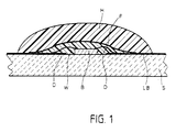
- Fig. 1 shows the basic structure of an encapsulated circuit according to the inventive method.
- a substrate S which suitably consists of A1 2 0 3 , a microelectronic component B, for example passivated with Si 3 N 4 , adheres with the conductor tracks LB in a known manner with bonding wires D, which consist of gold, aluminum or other highly conductive metal is electrically connected.
- the module B and the bond wires are located within a soft plastic layer W. This is covered with a film F which contains a metal layer and the structure of which is described below.
- epoxy resin H with a high-purity Si0 2 or chalk filling.
- Wacker has developed and made available elastomers made of silicone and (approx. 50%) thermoplastic polymers which, compared to pure silicone elastomers, are characterized by increased mechanical strength, satisfactory adhesion to components, ceramics, metal, etc. and Above all, they are characterized by low water vapor permeability and are therefore ideally suited as a top layer.
- the elastomers used can be welded to the plastic film by thermocompression.
- a complete solution according to the invention is that the z. B. passivated with Si 3 N 4 , bonded to a substrate S microelectronic circuit B with a soft plastic layer W in the operating temperature range, which can be sealed or glued with a heat and crack-free deformable plastic-metal-plastic composite film F and if necessary is encapsulated and solidified with a highly filled, highly cross-linked synthetic resin H.
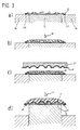
- the tried and tested heat sealing method according to FIG. 2 is particularly well suited for the efficient implementation of the method according to the invention.
- the bonded component B is initially on the substrate S.
- the bond wires D electrically connect the component B to the conductor tracks LB.
- Passivation P prevents unwanted corrosion.
- the prepared circuit is first preheated.
- a low-viscosity, liquid elastomer W is then applied in accordance with step b).
- the resulting layer W is heat sealable.
- the metal composite foil F is placed on and pressed onto the soft layer W with a hollow stamp ST heated to approximately 200 ° C.
- the plastic side of the film F facing the layer W connects to it under the influence of heat and pressure.
- the filling solidifies u.
- deformation of the composite film during punching has proven to be advantageous.
- This method is based on the fact that z. B. modified with polyolefins silicones with polypropylene films at 160 - 190 ° C under pressure can be easily deformed and sealed.
- Rolled copper or aluminum foils are preferred as the inner metal layer, and high-purity polypropylene-polyethylene, polyethylene tereplethalate, polycarbonate, polyimide foils are suitable as covers. Delamination or cracking is unknown with such composite films, the gas and moisture permeability is many orders of magnitude lower than with epoxy resin or silicone elastomer packaging. Diffusion and permeation is only along the approx. 10 - 100 u. thick, but millimeter-long boundary layer between the semiconductor circuit and aluminum layer possible.
- the rolled metal foil which is electrically insulated on both sides, also facilitates rapid temperature compensation in the case of power semiconductor circuits or power hybrid circuits.
- the substrate S with the components is located on a carrier consisting of the inner part Ti and the outer part Ta.
- the edge of the substrate protrudes beyond the inner part Ti of the carrier and is printed on the back with a solder ring LK.
- the conductor tracks are insulated from the solder ring with a dielectric layer.
- Method step b) takes place as in the example according to FIG. 2.
- a film F preformed in accordance with the topology of the components is used here.
- the stamp ST is also adapted to the shape of the film. After the film has been applied, it is folded over at the edges of the substrate after removal of the outer part TA of the carrier and is soldered to the solder ring as shown in FIG. 3d. Then you can the element can be cast with epoxy resin H. Copper foils laminated on one side are particularly suitable for soldering. The epoxy resin quartz potting serves as mechanical protection.
- the chip or the passivated semiconductor circuit is placed on the carrier and bonded at the connections.
- the chip and all bond connections are coated with a low-viscosity plastic, which is characterized by very low gas and water vapor permeability, high flexibility and sealability.
- a polyolefin-modified silicone solution in petrol is applied to the substrate primed with p-methyldisiloxane-methyl methacrylate.
- the thixotropic casting compound is applied mixed at 140 ° and cured for five hours.
- a thick-film hybrid circuit with semiconductor chips and discrete components is coated with a hot polyethylene / xylene solution, covered with a possibly cut pre-shaped composite film, pressed to the substrate, glued or sealed.
- the encapsulated hybrid circuit is then encapsulated or potted with a filled epoxy resin.
- a bonded hybrid circuit is preheated to approx. 100 ° C., placed on a vacuum holding device and covered with a copper (25 ⁇ ) adhesive film, which is pre-punched and pre-shaped in accordance with the circuit.
- the conductor tracks of the circuit are covered with dielectric paste at the intended contact or soldering points during screen printing. Before the film is sealed, these areas are printed with solder paste.
- the film is folded under vacuum, sealed with the resin, then soldered and encapsulated or cast with a filled epoxy resin.
Landscapes
- Engineering & Computer Science (AREA)
- Manufacturing & Machinery (AREA)
- Microelectronics & Electronic Packaging (AREA)
- Structures Or Materials For Encapsulating Or Coating Semiconductor Devices Or Solid State Devices (AREA)
- Encapsulation Of And Coatings For Semiconductor Or Solid State Devices (AREA)
- Non-Metallic Protective Coatings For Printed Circuits (AREA)
Description
- Die Erfindung betrifft ein Verfahren zum Einkapseln von mikroelektronischen Hybrid-Halbleiterschaltungen oder von mikroelektronischen Halbleiterbauelementen.
- Hochzuverlässige, mikroelektronische Schaltungen für professionelle, medizinische und militärische Anwendungen erfordern einen Langzeitigen Schutz gegen die Einwirkung von Feuchtigkeitsspuren oder korrosiven Stoffen. Zumeist verwendet man hierfür metallische oder keramische Gehäuse, die hermetisch dicht verschweißt oder verlötet sind. Derartige Gehäuse, z. B. Kovargehäuse, sowie die zugehörigen Verkapselungstechnologien, z. B. das Rollnaht-, Ringbuckel-, Elektronen- oder Laserstrahl-Schweißen oder die Glaslot- sowie die Anglasungstechniken sind sehr aufwendig bzw. kostspielig und für Mikroschaltungen thermisch nicht unkritisch.
- Es wird daher seit Jahren versucht, die in der kommerziellen Elektronik, vor allem in der Konsumelektronik, bewährten, preiswerten sowie rationellen Kunststoffverpackungen für professionelle mikroelektronische Schaltungen hochzuzüchten.
- Es wurden hierfür zahlreiche spezielle Kunststoffmassen und Vergußtechniken entwickelt, die z. B. in DE-PS-2 347 049, DE-AS-2 538119, DE-AS-2 628 823, DE-AS-2 545 471, DE-OS-2 748 523, DE-OS-2 656 139, DE-OS-3 137 480 und DE-OS-3 151 902 beschrieben sind.
- Es hat sich aber gezeigt, daß die vorgeschlagenen Lösungen nicht zu völlig gas- und wasserdichten Abdichtungen führen. Der höhere Ausdehnungskoeffizient der Kunststoff-Verkapselung führt nämlich bei größeren Temperaturschwankungen an den Substratgrenzflächen zu Spannungen und damit zu Ablösungen und Rissen. Bei hohen Zuverlässigkeitsanforderungen und starken thermomechanischen Schockbeanspruchungen (-65°/+250°C) werden daher Kunststoffkapselungen nicht verwendet. Auch nach MIL-M-38510 werden bisher nur hermetisch verschweißte oder verlötete Metall- und Keramikgehäuse akzeptiert.
- Es ist ferner beispielsweise aus der DE-PS-2 347 049 bekannt, daß sich gebondete Halbleiterschaltungen durch elastische Abdeckschichten aus Kunststoffschaum schützen lassen. Bei starken Temperaturwechselbeanspruchungen muß aber insbesondere bei Schaumpolstern mit hohen thermomechanischen Spannungen in der Kapsel gerechnet werden, so daß sich die Grenzflächen trennen und Feuchtigkeit bzw. korrosive Stoffe entlang der Fugen eindringen können. Vermeidet man die Kapsel und vergießt die Abdeckschicht direkt mit einem im Ausdehnungskoeffizienten annähernd angepaßten Kunstharz (DE-OS-2 922 005), so ist die Wasserdampfundurchlässigkeit bzw. Riß- sowie Porenfreiheit nicht gewährleistet. Auch ist bei Epoxidharz-Silikonelastomer-Kombinationen (DE-OS-2 922 005) bei starken Temperaturwechselbeanspruchungen infolge der geringen Haftfestigkeit mit einem Ablösen zu rechnen, so daß sich bei Haarrissen die Feuchtigkeit über die gesamte Trennfuge verteilen kann.
- Es ist nun ferner bekannt (DE-OS-2 551 778, DE-PS-1 514 478), Kondensatoren mit beidseitig kunststoff-kaschierten Metallfolien feuchtdicht zu verkapseln. Diese Technik setzt aber eine geometrisch einfache Bauelementenform und eine haftfest aufschrumpfende Kunststoff-Kaschierung voraus. Hybride, die mit gebondeten IC's oder kleinen diskreten Bauelementen dicht bestückt sind, lassen sich nicht drucklos fugen-, hohlraumfrei und haftfest kaschieren, so daß es bei Temperaturwechselbeanspruchungen zwischen -65° und +125°C zu Ablösungen oder Drahtverformungen kommt, die sich auch auf die elektrischen Funktionseigenschaften auswirken.
- Weiterhin zählt zum Stand der Technik das aus der FR-A-2 404 992 bekannte Halbleiterbauelement, bei dem die auf einem Substrat-befindlichen Bauelement in eine weiche, siegelfähige Kunststoffschicht eingegossen und anschließend mit Kunstharz verkapselt sind.
- Aus der EP-A-0 122 687 ist ferner eine laminierte Verkapselung bekannt, bei der eine Metallschicht auf eine Kunststoffschicht aufgetragen wird und eine weitere Kunststoffverstärkungsschicht ist auf der Metallschicht vorgesehen, während der Hohlraum zwischen Verkapselung und Bauelement mit einem hygroskopischen Material gefüllt wird. Aus der JP-A-57 128 948 ist ein eingekapseltes Halbleiterelement bekannt geworden, bei dem das Bauelement in eine Silikonschicht eingegossen und anschließend mit einer Kunststoff-Folie abgedeckt wird.
- Alle bekannten Verfahren sind nicht dazu geeignet, die notwendige Sicherung der Verkapselung gegen Umwelteinflüsse insbesondere auch gegen mechanische Schocks und hohe Temperatur-Wechselbeanspruchungen zwischen -65°C und 125°C zu gewährleisten.
- Es ist die Aufgabe der Erfindung, ein Verfahren zu schaffen, das die Vorteile der Kunststoffverpackung, u.a. die einfache, rationelle Formgebung, gute elektrische Isolation und geringe Material kosten, mit den Vorteilen der Metall-und Keramikgehäuse, nämlich thermomechanische Schockfestigkeit und Dichtigkeit, weitgehend verbindet und diese Eigenschaften noch verbessert.
- Gemäß der Erfindung wird diese Aufgabe durch die Verfahrensschritte gemäß dem Kennzeichnungsteil der Ansprüche 1 bzw. 2 gelöst.
- Die Unterfütterung der Kunststoff-Metall-Folie mit einer siegelfähigen Abdeckung, die sich fest mit der übergossenen Schaltung verbindet, löst die bisher aufgetretenen Probleme.
- Einzelheiten der Erfindung ergeben sich aus den Unteransprüchen und der Beschreibung, in der anhand der Zeichnung mehrere Ausführungsbeispiele erläutert werden. Es zeigen:
- Fig. 1 den Aufbau einer nach dem erfindungsgemäßen Verfahren eingekapselten Schaltung,
- Fig. 2 schematisch die Schritte einer ersten und
- Fig. 3 einer zweiten Variante des Verfahrens.
- Fig. 1 zeigt den grundsätzlichen Aufbau einer nach dem erfindungsgemäßen Verfahren eingekapselten Schaltung. Auf einem Substrat S, das zweckmäßig aus A1203 besteht, haftet ein beispielsweise mit Si3N4 passivierter mikroelektronischer Baustein B, der in bekannter Weise mit Bonddrähten D, die aus Gold, Aluminium oder anderem hochleitfähigem Metall bestehen, mit den Leiterbahnen LB elektrisch verbunden ist. Der Baustein B und die Bonddrähte befinden sich innerhalb einer weichen Kunststoffschicht W. Diese ist mit einer Folie F abgedeckt, die eine Metallschlcht enthält und deren Aufbau weiter unten beschrieben wird. Schließlich ist das Ganze mit Epoxidharz H mit hochreiner Si02-oder Kreidefüllung eingekapselt.
- In den letzten Jahren wurden von der Fa. Wacker Elastomere aus Silikon und (ca. 50 %) thermoplastischen Polymeren entwickelt und zur Verfügung gestellt, die sich gegenüber den reinen Silikonelastomeren durch erhöhte mechanische Festigkeit, befriedigende Haftung auf Bauteilen, Keramik, Metall usw. sowie vor allem durch geringe Wasserdampfdurchlässigkeit auszeichnen und damit als Deckschicht hervorragend geeignet sind. Zudem wurde im Rahmen der der Erfindung zugrundeliegenden Untersuchungen gefunden, daß sich die verwendeten Elastomere durch Thermokompression mit der Kunststoff-Folie verschweißen lassen.
- Hieraus ergibt sich ein Verbundsystem aus Kunststoff-Metallschichten. Die unterschiedlichen Ausdehnungskoeffizienten, die elektrische Kontaktierung und weitere Schwierigkeiten stellen sich einer solchen Lösung, z. B. einer kombinierten Verguß- und Aufdampftechnik, zunächst entgegen. Die metallischen Aufdampfschichten sind nicht gasdicht und können durch Kunstharze, z. B. Epoxidharze, bei Wärme- und Feuchtigkeitseinwirkung angegriffen werden.
- Eine vollständige Lösung nach der Erfindung besteht also darin, daß die z. B. mit Si3N4 passivierte, auf ein Substrat S gebondete mikroelektronische Schaltung B mit einer im Betriebstemperaturbereich weichen Kunststoffschicht W überzogen wird, die sich mit einer warm- und rißfrei verformbaren Kunststoff-Metall-Kunststoff-Verbundfolie F versiegeln oder verkleben läßt und ggf. mit einem hochgefüllten, stark vernetzten Kunstharz H verkapselt und verfestigt wird.
- Zur rationellen Durchführung des erfindungsgemäßen Verfahrens eignet sich besonders gut das bewährte Heißsiegelverfahren nach Fig. 2.
- Dabei befindet sich gemäß Schritt a) zunächst der gebondete Baustein B auf dem Substrat S. Die Bond-Drähte D verbinden den Baustein B elektrisch mit den Leiterbahnen LB. Eine Passivierung P verhindert unerwünschte Korrosion. In diesem Zustand wird die vorbereitete Schaltung zunächst vorgewärmt.
- Sodann wird gemäß Schritt b) ein niederviskoses, flüssiges Elastomer W aufgebracht. Die hieraus hervorgehende Schicht W ist heißsiegelfähig. Beim dritten Schritt c) wird die Metall-Verbundfolie F aufgelegt und mit einem auf etwa 200°C erhitzten Hohlstempel ST auf die weiche Schicht W aufgepreßt. Dabei verbindet sich die der Schicht W zugewandte Kunststoffseite der Folie F mit derselben unter dem Einfluß von Wärme und Druck. Beim nachfolgenden Abkühlen verfestigt sich die Füllung u. Daneben hat sich eine Verformung der Verbundfolie beim Ausstanzen als vorteilhaft erwiesen.
- Sodann wird ggf. gemäß Verfahrensschritt d) das bisher erzeugte Element mit einem Epoxidharz H vergossen. Das in Fig. 2e dargestellte Endprodukt entspricht dem nach Fig. 1.
- Dieses Verfahren beruht also darauf, daß z. B. mit Polyolefinen modifizierte Silikone mit Polypropylenfolien bei 160 - 190° C unter Druck leicht verformt und versiegelt werden können. Als innere Metallschicht kommen vorzugsweise gewalzte Kupfer- oder Aluminium-Folien, als Abdeckung hochreine Polypropylen-Polyäthylen-, Polyäthylentereplethalat-, Polycarbonat-, Polyimid-Folien in Frage. Eine Delaminierung oder Rißbildung ist bei derartigen Verbundfolien unbekannt, die Gas- und Feuchtigkeitsdurchlässigkeit um viele Zehnerpotenzen kleiner als bei Epoxidharz- oder Silikonelastomer-Verpackungen. Eine Diffusion und Permeation ist nur entlang der ca. 10 - 100 u. dicken, aber millimeterlangen Grenzschicht zwischen Halbleiterschaltung und Aluminiumschicht möglich.
- Die beidseitig elektrisch isolierte, gewalzte Metallfolie erleichtert bei Leistungshalbleiterschaltungen oder Leistungshybridschaltungen zudem einen schnellen Temperaturausgleich.
- Vorteilhaft werden zum Aufbringen der Folien an sich bekannte automatische Die-Bonder verwendet. Diese sind zweckmäßig mit dem Stanzwerkzeug für die Folien im gleichen Arbeitstakt gekoppelt.
- Fig. 3 zeigt eine andere Variante des erfindungsgemäßen Verfahrens. Hierbei befindet sich auf einem aus Innenteil Ti und Außenteil Ta bestehenden Träger das Substrat S mit den Bauelementen. Der Rand des Substrats ragt über den Innenteil Ti des Trägers hinaus und ist rückseitig mit einem Lotkranz LK bedruckt. Die Leiterbahnen sind beim Dickschicht-Siebdruck mit einer Dielektrikumsschicht gegen den Lotkranz isoliert. Der Verfahrensschritt b) erfolgt wie im Beispiel nach Fig. 2.
- Im Verfahrensschritt c), also beim Aufbringen der Folie, wird hier eine entsprechend der Topologie der Bauelemente vorgeformte Folie F verwendet. Ebenso ist der Stempel ST der Formgebung der Folie angepaßt. Nach Aufbringen der Folie wird diese an den Rändern des Substrates nach Entfernen des Außenteiles TA des Trägers umgefalzt und entsprechend Fig. 3d mit dem Lotkranz verlötet. Anschließend kann das Element mit Epoxidharz H vergossen werden. Besonders geeignet zum Verlöten sind einseitig kaschierte Kupferfolien. Der Epoxidharz-Quarz-Verguß dient als mechanischer Schutz.
- Im folgenden werden drei Ausführungsbeispiele angegeben.
- Der Chip bzw. die passivierte Halbleiterschaltung wird auf den Carrier gelegt und an den Anschlüssen gebondet. Der Chip sowie alle Bondanschlüsse werden mit einem niederviskosen Kunststoff überzogen, der durch eine sehr geringe Gas- und Wasserdampfdurchlässigkeit, hohe Flexibilität und Siegelfähigkeit gekennzeichnet ist. In diesem Fall wird eine polyolefinmodifizierte Silikon-Lösung in Benzin auf das mit p-Methyldisiloxan-Methylmethacrylat grundierte Substrat gebracht.
- Aus einer Polypropylen-(75 µ)-, Aluminium-(10 µ)-, Polyäthylenterephtalat-(15 µ)-Verbundfolie wird heiß (ca. 120°) eine für den Chip dimensionierte Kappe ausgestanzt, mit einem Die-Bonder über den Chip-Carrier gestülpt und mittels eines heißen Hohlstempels mit dem Weichverguß dicht versiegelt. Der ca. 180° C heiße Hohlstempel preßt die Folie mit dem flüssigen Weichverguß so auf das Substrat, daß die Siegelschicht unter ca. 20 µ liegt. Anschließend wird mit hochreinen, flexiblen Epoxidharz-/Quarzmehl-Vergußmassen die Kappe bzw. verkapselte Schaltung vergossen. Als Vergußmasse eignet sich ein Harz aus
- 100 Gew. T. ECN 1280 (CIBA),
- 120 Gew. T. Dodeceylbernsteinsäureanhydrid, 0,5 Gew. T. Piperidin,
- 2 Gew. T. p-Methyldisiloxan-Methylmethacrylat,
- 300 Gew. T. vakuumgetrocknetes, hochreines Quarzmehl (X-30 µ).
- Die thixotrope Vergußmasse wird bei 140° gemischt aufgebracht und fünf Stunden gehärtet.
- Eine Dickschicht-Hybridschaltung mit Halbleiterchips und diskreten Bauelementen wird mit einer heißen Polyethylen/Xylol-Lösung lackiert, mit einer entsprechend zugeschnittenen evtl. vorgeformten Verbundfolie abgedeckt, an das Substrat gepreßt, verklebt bzw. versiegelt. Die verkapselte Hybridschaltung wird anschließend mit einem gefüllten Epoxidharz umpreßt bzw. vergossen.
- Eine gebondete Hybridschaltung wird auf ca. 100°C vorgewärmt, auf eine Vakuum-Haltevorrichtung gebracht und mit einer Kupfer-(25 µ)-Klebefolie, die entsprechend der Schaltung vorgestanzt und vorgeformt ist, abgedeckt.
- Die Leiterbahnen der Schaltung werden beim Siebdruck an den vorgesehenen Kontakt- bzw. Lötstellen mit Dielektrikumspaste überschichtet. Vor der Folienversiegelung werden diese Stellen mit Lötpaste bedruckt.
- Unter Vakuum wird die Folie gefalzt, mit dem Harz versiegelt, anschließend verlötet und mit einem gefüllten Epoxidharz umpreßt oder vergossen.
Claims (9)
Applications Claiming Priority (2)
| Application Number | Priority Date | Filing Date | Title |
|---|---|---|---|
| DE3442131 | 1984-11-17 | ||
| DE19843442131 DE3442131A1 (de) | 1984-11-17 | 1984-11-17 | Verfahren zum einkapseln von mikroelektronischen halbleiter- und schichtschaltungen |
Publications (2)
| Publication Number | Publication Date |
|---|---|
| EP0202279A1 EP0202279A1 (de) | 1986-11-26 |
| EP0202279B1 true EP0202279B1 (de) | 1989-08-02 |
Family
ID=6250592
Family Applications (1)
| Application Number | Title | Priority Date | Filing Date |
|---|---|---|---|
| EP85905776A Expired EP0202279B1 (de) | 1984-11-17 | 1985-11-18 | Verfahren zum einkapseln von mikroelektronischen halbleiter- und schichtschaltungen |
Country Status (5)
| Country | Link |
|---|---|
| US (1) | US4784872A (de) |
| EP (1) | EP0202279B1 (de) |
| JP (1) | JPH0626223B2 (de) |
| DE (1) | DE3442131A1 (de) |
| WO (1) | WO1986003055A1 (de) |
Cited By (2)
| Publication number | Priority date | Publication date | Assignee | Title |
|---|---|---|---|---|
| DE102005041100A1 (de) * | 2005-08-30 | 2007-03-08 | Siemens Ag | Halbleiterstruktur mit einem lateral funktionalen Aufbau |
| CN108401367A (zh) * | 2018-02-26 | 2018-08-14 | 广州致远电子有限公司 | 塑封电子模块及其制作方法 |
Families Citing this family (55)
| Publication number | Priority date | Publication date | Assignee | Title |
|---|---|---|---|---|
| US5476211A (en) * | 1993-11-16 | 1995-12-19 | Form Factor, Inc. | Method of manufacturing electrical contacts, using a sacrificial member |
| US5917707A (en) * | 1993-11-16 | 1999-06-29 | Formfactor, Inc. | Flexible contact structure with an electrically conductive shell |
| JP2585006B2 (ja) * | 1987-07-22 | 1997-02-26 | 東レ・ダウコーニング・シリコーン株式会社 | 樹脂封止型半導体装置およびその製造方法 |
| DE3725269A1 (de) * | 1987-07-30 | 1989-02-09 | Messerschmitt Boelkow Blohm | Verfahren zum einkapseln von mikroelektronischen halbleiter- und schichtschaltungen |
| US4903118A (en) * | 1988-03-30 | 1990-02-20 | Director General, Agency Of Industrial Science And Technology | Semiconductor device including a resilient bonding resin |
| EP0361194A3 (de) * | 1988-09-30 | 1991-06-12 | Siemens Aktiengesellschaft | Verfahren zum Umhüllen von elektrischen oder elektronischen Bauelementen oder Baugruppen und Umhüllung für elektrische oder elektronische Bauelemente oder Baugruppen |
| US5219795A (en) * | 1989-02-07 | 1993-06-15 | Fujitsu Limited | Dual in-line packaging and method of producing the same |
| JPH0322543A (ja) * | 1989-06-05 | 1991-01-30 | Siemens Ag | 電子デバイスの被覆方法及び装置 |
| JPH0521655A (ja) * | 1990-11-28 | 1993-01-29 | Mitsubishi Electric Corp | 半導体装置および半導体装置用パツケージ |
| US4996170A (en) * | 1990-07-30 | 1991-02-26 | Motorola, Inc. | Molding process for encapsulating semiconductor devices using a thixotropic compound |
| DE4027478A1 (de) * | 1990-08-30 | 1992-03-05 | Robert Dipl Ing Michaelides | Schaltungsaufbau und herstellungsverfahren |
| DE4101042C1 (en) * | 1991-01-16 | 1992-02-20 | Messerschmitt-Boelkow-Blohm Gmbh, 8012 Ottobrunn, De | Contact and encapsulation of micro-circuits using solder laser - and laser transparent contact film segments with conductor sheets of solderable material, geometrically associated with solder protuberances |
| US5271953A (en) * | 1991-02-25 | 1993-12-21 | Delco Electronics Corporation | System for performing work on workpieces |
| US5240746A (en) * | 1991-02-25 | 1993-08-31 | Delco Electronics Corporation | System for performing related operations on workpieces |
| US5368899A (en) * | 1992-02-28 | 1994-11-29 | Delco Electronics Corp. | Automatic vertical dip coater with simultaneous ultraviolet cure |
| US5390082A (en) * | 1992-07-06 | 1995-02-14 | International Business Machines, Corp. | Chip carrier with protective coating for circuitized surface |
| US5249101A (en) * | 1992-07-06 | 1993-09-28 | International Business Machines Corporation | Chip carrier with protective coating for circuitized surface |
| EP0620591A1 (de) * | 1993-04-12 | 1994-10-19 | Delco Electronics Corporation | Silikonverkapselung einer Flipclipanordnung |
| JP3258764B2 (ja) * | 1993-06-01 | 2002-02-18 | 三菱電機株式会社 | 樹脂封止型半導体装置の製造方法ならびに外部引出用電極およびその製造方法 |
| SG68542A1 (en) * | 1993-06-04 | 1999-11-16 | Seiko Epson Corp | Semiconductor device and manufacturing method thereof |
| US7084656B1 (en) | 1993-11-16 | 2006-08-01 | Formfactor, Inc. | Probe for semiconductor devices |
| US5820014A (en) | 1993-11-16 | 1998-10-13 | Form Factor, Inc. | Solder preforms |
| US20020053734A1 (en) | 1993-11-16 | 2002-05-09 | Formfactor, Inc. | Probe card assembly and kit, and methods of making same |
| US7200930B2 (en) | 1994-11-15 | 2007-04-10 | Formfactor, Inc. | Probe for semiconductor devices |
| US7073254B2 (en) | 1993-11-16 | 2006-07-11 | Formfactor, Inc. | Method for mounting a plurality of spring contact elements |
| GB2295722B (en) * | 1994-11-30 | 1997-12-17 | Motorola Ltd | Method of packaging integrated circuits |
| JPH09155918A (ja) * | 1995-12-07 | 1997-06-17 | Matsushita Electric Ind Co Ltd | 樹脂封止電子製品の製造方法 |
| US8033838B2 (en) | 1996-02-21 | 2011-10-11 | Formfactor, Inc. | Microelectronic contact structure |
| US5994152A (en) | 1996-02-21 | 1999-11-30 | Formfactor, Inc. | Fabricating interconnects and tips using sacrificial substrates |
| EP0794616B1 (de) * | 1996-03-08 | 2003-01-29 | Matsushita Electric Industrial Co., Ltd. | Elektronisches Bauteil und Herstellungsverfahren |
| DE19736090B4 (de) * | 1997-08-20 | 2005-04-14 | Daimlerchrysler Ag | Bauelement mit Schutzschicht und Verfahren zur Herstellung einer Schutzschicht für ein Bauelement |
| US6138349A (en) | 1997-12-18 | 2000-10-31 | Vlt Corporation | Protective coating for an electronic device |
| US5987358A (en) * | 1998-02-17 | 1999-11-16 | Intermedics, Inc. | Semiconductor device packaging and method of fabrication |
| US6194290B1 (en) * | 1998-03-09 | 2001-02-27 | Intersil Corporation | Methods for making semiconductor devices by low temperature direct bonding |
| JP2000219234A (ja) * | 1999-01-29 | 2000-08-08 | Bridgestone Sports Co Ltd | ゴルフボール用箱 |
| US6187613B1 (en) * | 1999-11-04 | 2001-02-13 | Industrial Technology Research Institute | Process for underfill encapsulating flip chip driven by pressure |
| US6589802B1 (en) * | 1999-12-24 | 2003-07-08 | Hitachi, Ltd. | Packaging structure and method of packaging electronic parts |
| DE10049288B4 (de) | 2000-10-04 | 2004-07-15 | Infineon Technologies Ag | Elektronische Bauteile und eine Folienband zum Verpacken von Bonddrahtverbindungen elektronischer Bauteile sowie deren Herstellungsverfahren |
| FR2819935B1 (fr) * | 2001-01-19 | 2003-04-25 | Ela Medical Sa | Procede de fabrication de circuits electroniques hybrides pour dispositifs medicaux implantables actifs |
| US6444501B1 (en) * | 2001-06-12 | 2002-09-03 | Micron Technology, Inc. | Two stage transfer molding method to encapsulate MMC module |
| US20060182952A1 (en) * | 2002-01-08 | 2006-08-17 | Justo Roger J | Encapsulated thermally conductive electrically insulating assembly and method to prepare same |
| DE10216652A1 (de) * | 2002-04-15 | 2003-10-23 | Orga Kartensysteme Gmbh | Spritzgussverfahren zur Herstellung einer Chipkarte und nach diesem Verfahren hergestellte Chipkarte |
| DE10303449B4 (de) * | 2003-01-29 | 2007-04-26 | Siemens Ag | Verfahren zum Umhüllen eines elektronischen Bauelementes |
| TWI246780B (en) * | 2003-03-10 | 2006-01-01 | Toyoda Gosei Kk | Solid-state component device and manufacturing method thereof |
| DE102004049955B4 (de) * | 2004-10-13 | 2008-12-04 | Schott Ag | Verfahren zur Herstellung eines optischen Bauelements, insbesondere einer OLED |
| US7523546B2 (en) * | 2005-05-04 | 2009-04-28 | Nokia Corporation | Method for manufacturing a composite layer for an electronic device |
| US20080087323A1 (en) * | 2005-05-09 | 2008-04-17 | Kenji Araki | Concentrator Solar Photovoltaic Power Generating Apparatus |
| DE102006012615A1 (de) * | 2006-03-20 | 2007-10-11 | Kromberg & Schubert Gmbh & Co. Kg | Umhülltes Bauelement und Verfahren zu dessen Herstellung |
| US8051557B2 (en) * | 2006-03-31 | 2011-11-08 | Princo Corp. | Substrate with multi-layer interconnection structure and method of manufacturing the same |
| DE102007035181B4 (de) * | 2007-07-27 | 2011-11-10 | Epcos Ag | Verfahren zur Herstellung eines Moduls und Modul |
| US8957509B2 (en) * | 2011-06-23 | 2015-02-17 | Stats Chippac Ltd. | Integrated circuit packaging system with thermal emission and method of manufacture thereof |
| JP2013055150A (ja) * | 2011-09-01 | 2013-03-21 | Toshiba Corp | 半導体装置及びその製造方法 |
| DE202012008242U1 (de) | 2012-02-26 | 2012-11-09 | Kromberg & Schubert Kg | Verbindung eines ersten metallischen Bauteils mit einemumhüllten zweiten metallischen Bauteil |
| US11914293B2 (en) | 2017-01-31 | 2024-02-27 | Flint Group Germany Gmbh | Radiatioin-curable mixture containing low-functionalised, partially saponified polyvinyl acetate |
| CN110678332B (zh) | 2017-03-27 | 2021-11-26 | 富林特集团德国有限公司 | 制造图形凸纹结构的方法 |
Family Cites Families (20)
| Publication number | Priority date | Publication date | Assignee | Title |
|---|---|---|---|---|
| US3608029A (en) * | 1969-03-12 | 1971-09-21 | Vitramon Inc | Process for encapsulating electronic components |
| CH560999A5 (de) * | 1973-08-16 | 1975-04-15 | Bbc Brown Boveri & Cie | |
| US3876461A (en) * | 1973-09-04 | 1975-04-08 | Motorola Inc | Semiconductor process |
| GB1528203A (en) * | 1974-10-18 | 1978-10-11 | Matsushita Electric Industrial Co Ltd | Epoxy composition for encasing semi-conductor devices |
| JPS5171792A (de) * | 1974-12-19 | 1976-06-21 | Minolta Camera Kk | |
| DE2551778A1 (de) * | 1975-11-18 | 1977-05-26 | Siemens Ag | Feuchtedicht umhuelltes elektrisches bauelement |
| US4048356A (en) * | 1975-12-15 | 1977-09-13 | International Business Machines Corporation | Hermetic topsealant coating and process for its formation |
| DE2628823C3 (de) * | 1976-06-26 | 1979-03-01 | Standard Elektrik Lorenz Ag, 7000 Stuttgart | Glaskeramischer Werkstoff zur Verkapselung von Halbleiterbauelementen |
| FR2404992A1 (fr) * | 1977-10-03 | 1979-04-27 | Cii Honeywell Bull | Circuits electriques integres proteges, substrats d'interconnexion proteges comportant de tels circuits et procede d'obtention desdits circuits et substrats |
| DE2748523A1 (de) * | 1977-10-28 | 1979-05-03 | Siemens Ag | Epoxid-niederdruckpressmasse |
| DE2922005A1 (de) * | 1979-05-30 | 1980-12-04 | Siemens Ag | Halbleiterbauelement mit passiviertem halbleiterkoerper |
| US4327369A (en) * | 1979-08-06 | 1982-04-27 | Hi-Tech Industries, Inc. | Encapsulating moisture-proof coating |
| JPS6018145B2 (ja) * | 1980-09-22 | 1985-05-09 | 株式会社日立製作所 | 樹脂封止型半導体装置 |
| JPS5790967A (en) * | 1980-11-27 | 1982-06-05 | Nec Corp | Semiconductor device sealed with resin |
| US4330637A (en) * | 1981-01-05 | 1982-05-18 | Western Electric Company, Inc. | Encapsulated electronic devices and encapsulating compositions |
| JPS57128948A (en) * | 1981-02-02 | 1982-08-10 | Sharp Corp | Electronic part |
| US4388132A (en) * | 1981-06-01 | 1983-06-14 | Burroughs Corporation | Method of attaching a protective film to an integrated circuit |
| DE3222791A1 (de) * | 1982-06-18 | 1983-12-22 | Siemens AG, 1000 Berlin und 8000 München | Verfahren zum herstellen von halbleiter-bauelementen |
| JPS59172253A (ja) * | 1983-03-18 | 1984-09-28 | Mitsubishi Electric Corp | 半導体装置 |
| DE3310654A1 (de) * | 1983-03-24 | 1984-09-27 | Standard Elektrik Lorenz Ag, 7000 Stuttgart | Verfahren zum versiegeln von flachen hybridbausteinen |
-
1984
- 1984-11-17 DE DE19843442131 patent/DE3442131A1/de active Granted
-
1985
- 1985-11-18 US US06/909,118 patent/US4784872A/en not_active Expired - Fee Related
- 1985-11-18 JP JP60505156A patent/JPH0626223B2/ja not_active Expired - Lifetime
- 1985-11-18 WO PCT/DE1985/000475 patent/WO1986003055A1/de not_active Ceased
- 1985-11-18 EP EP85905776A patent/EP0202279B1/de not_active Expired
Cited By (3)
| Publication number | Priority date | Publication date | Assignee | Title |
|---|---|---|---|---|
| DE102005041100A1 (de) * | 2005-08-30 | 2007-03-08 | Siemens Ag | Halbleiterstruktur mit einem lateral funktionalen Aufbau |
| CN108401367A (zh) * | 2018-02-26 | 2018-08-14 | 广州致远电子有限公司 | 塑封电子模块及其制作方法 |
| CN108401367B (zh) * | 2018-02-26 | 2020-08-14 | 广州致远电子有限公司 | 塑封电子模块及其制作方法 |
Also Published As
| Publication number | Publication date |
|---|---|
| DE3442131A1 (de) | 1986-05-22 |
| DE3442131C2 (de) | 1988-12-01 |
| EP0202279A1 (de) | 1986-11-26 |
| WO1986003055A1 (en) | 1986-05-22 |
| JPH0626223B2 (ja) | 1994-04-06 |
| US4784872A (en) | 1988-11-15 |
| JPS62500900A (ja) | 1987-04-09 |
Similar Documents
| Publication | Publication Date | Title |
|---|---|---|
| EP0202279B1 (de) | Verfahren zum einkapseln von mikroelektronischen halbleiter- und schichtschaltungen | |
| EP0302165B1 (de) | Verfahren zum Einkapseln von mikroelektronischen Halbleiter- und Schichtschaltungen | |
| DE102009000587B4 (de) | Verfahren zur Herstellung eines Moduls mit einer gesinterten Verbindung zwischen einem Halbleiterchip und einer Kupferoberfläche | |
| DE69027781T2 (de) | Packung mit metallstiftmuster und dielektrischer polymerdichtung | |
| DE102008021167B3 (de) | Verfahren zur Erzeugung einer hermetisch dichten, elektrischen Durchführung mittels exothermer Nanofolie und damit hergestellte Vorrichtung | |
| DE102014213564B4 (de) | Halbleitervorrichtung und Verfahren zu ihrer Herstellung | |
| DE102014102006B4 (de) | Halbleitermodul | |
| US4363076A (en) | Integrated circuit package | |
| DE19518753B4 (de) | Halbleitervorrichtung und Verfahren zu ihrer Herstellung | |
| US4558510A (en) | Method of producing a semiconductor device | |
| EP2743973A2 (de) | Verfahren zur Kontaktierung eines Halbleiterelements mittels Schweißens eines Kontaktelements an eine Sinterschicht auf dem Halbleiterelement und Halbleiterbauelement mit erhöhter Stabilität gegenüber thermomechanischen Einflüssen | |
| WO1992004729A1 (en) | Leadframe for molded plastic electronic packages | |
| DE102013108148A1 (de) | Elektrische Vorrichtungspackung mit einem Laminat und Verfahren zur Herstellung einer elektrischen Vorrichtungspackung mit einem Laminat | |
| US5814882A (en) | Seal structure for tape carrier package | |
| DE102017220258B4 (de) | Halbleitersensorbauelement und Verfahren zum Herstellen desselben | |
| EP2803082A1 (de) | Elektronisches bauteil mit korrosionsgeschützter bondverbindung und verfahren zur herstellung des bauteils | |
| DE3019868A1 (de) | Verfahren zur herstellung von halbleiteranordnungen | |
| EP0157590B1 (de) | Verkapselte elektronische Anordnung | |
| DE102008040727A1 (de) | Verfahren und Vorrichtung zur Ermittlung der Rotortemperatur einer permanenterregten Synchronmaschine | |
| WO2006005304A2 (de) | Halbleiterbauteil mit einem halbleiterchip und elektrischen verbindungselementen zu einer leiterstruktur | |
| DE102008031231B4 (de) | Herstellungsverfahren für planare elektronsche Leistungselektronik-Module für Hochtemperatur-Anwendungen und entsprechendes Leistungselektronik-Modul | |
| EP0214465B1 (de) | Plattierverfahren für ein elektronisches Element | |
| DE4041224A1 (de) | Chip-modul aus wenigstens zwei halbleiterchips | |
| DE102025101192B3 (de) | Leistungsmodul und Verfahren zur Herstellung eines Leistungsmoduls | |
| JPH0831546B2 (ja) | ハイパワ−用回路基板及びその混成集積回路 |
Legal Events
| Date | Code | Title | Description |
|---|---|---|---|
| PUAI | Public reference made under article 153(3) epc to a published international application that has entered the european phase |
Free format text: ORIGINAL CODE: 0009012 |
|
| 17P | Request for examination filed |
Effective date: 19860710 |
|
| AK | Designated contracting states |
Kind code of ref document: A1 Designated state(s): FR GB IT |
|
| 17Q | First examination report despatched |
Effective date: 19880915 |
|
| GRAA | (expected) grant |
Free format text: ORIGINAL CODE: 0009210 |
|
| AK | Designated contracting states |
Kind code of ref document: B1 Designated state(s): FR GB IT |
|
| GBT | Gb: translation of ep patent filed (gb section 77(6)(a)/1977) | ||
| ET | Fr: translation filed | ||
| ITF | It: translation for a ep patent filed | ||
| PLBE | No opposition filed within time limit |
Free format text: ORIGINAL CODE: 0009261 |
|
| STAA | Information on the status of an ep patent application or granted ep patent |
Free format text: STATUS: NO OPPOSITION FILED WITHIN TIME LIMIT |
|
| 26N | No opposition filed | ||
| ITTA | It: last paid annual fee | ||
| PGFP | Annual fee paid to national office [announced via postgrant information from national office to epo] |
Ref country code: GB Payment date: 19951018 Year of fee payment: 11 |
|
| PGFP | Annual fee paid to national office [announced via postgrant information from national office to epo] |
Ref country code: FR Payment date: 19951107 Year of fee payment: 11 |
|
| PG25 | Lapsed in a contracting state [announced via postgrant information from national office to epo] |
Ref country code: GB Effective date: 19961118 |
|
| GBPC | Gb: european patent ceased through non-payment of renewal fee |
Effective date: 19961118 |
|
| PG25 | Lapsed in a contracting state [announced via postgrant information from national office to epo] |
Ref country code: FR Effective date: 19970731 |
|
| REG | Reference to a national code |
Ref country code: FR Ref legal event code: ST |