EP0201477A2 - Backenbrecher - Google Patents
Backenbrecher Download PDFInfo
- Publication number
- EP0201477A2 EP0201477A2 EP86890122A EP86890122A EP0201477A2 EP 0201477 A2 EP0201477 A2 EP 0201477A2 EP 86890122 A EP86890122 A EP 86890122A EP 86890122 A EP86890122 A EP 86890122A EP 0201477 A2 EP0201477 A2 EP 0201477A2
- Authority
- EP
- European Patent Office
- Prior art keywords
- jaw
- eccentric shaft
- jaw crusher
- eccentricity
- drive
- Prior art date
- Legal status (The legal status is an assumption and is not a legal conclusion. Google has not performed a legal analysis and makes no representation as to the accuracy of the status listed.)
- Granted
Links
- 238000006073 displacement reaction Methods 0.000 claims abstract description 3
- 239000011435 rock Substances 0.000 description 11
- 238000010276 construction Methods 0.000 description 5
- 230000008859 change Effects 0.000 description 2
- 230000009467 reduction Effects 0.000 description 2
- 230000005540 biological transmission Effects 0.000 description 1
- 230000006835 compression Effects 0.000 description 1
- 238000007906 compression Methods 0.000 description 1
- 230000005484 gravity Effects 0.000 description 1
- 238000005461 lubrication Methods 0.000 description 1
- 239000003550 marker Substances 0.000 description 1
- 230000007246 mechanism Effects 0.000 description 1
- 238000000034 method Methods 0.000 description 1
- 230000008569 process Effects 0.000 description 1
- 125000006850 spacer group Chemical group 0.000 description 1
Images


Classifications
-
- B—PERFORMING OPERATIONS; TRANSPORTING
- B02—CRUSHING, PULVERISING, OR DISINTEGRATING; PREPARATORY TREATMENT OF GRAIN FOR MILLING
- B02C—CRUSHING, PULVERISING, OR DISINTEGRATING IN GENERAL; MILLING GRAIN
- B02C1/00—Crushing or disintegrating by reciprocating members
- B02C1/02—Jaw crushers or pulverisers
- B02C1/025—Jaw clearance or overload control
Definitions
- the invention relates to a jaw crusher with a stationary supported jaw and a counter jaw which can be driven relative to this jaw about a pivot axis for reciprocating movement, in which the driven counter jaw is moved by an eccentric shaft via toggle levers.
- jaw crushers of this type which are state of the art as toggle levers or double rocker crushers
- medium and large pieces of rock can be mechanically crushed in a simple and effective manner.
- the use of toggle levers for the drive allows the movable jaw to be curved and to work with a pivot point that is relatively high and close to the line of symmetry of the breaking angle with a minimum of friction during the breaking process and a large stroke in the area of the breaking jaw. In this way, the surface wear is evened out and the crushing jaw wear is reduced.
- the center of gravity of the rocker can also be chosen so that the required idle power is reduced.
- the pressure component can be adjusted in such a way that it is directed downwards, which causes the rock to be crushed to be drawn in well and the throughput rate is increased.
- the inexpensive and constant kinematics enables the user to approach an extended toggle lever and the associated high refractive powers with low drive power, which also has advantages for the design of the overload protection.
- This construction also ensures a constant stroke of the crushing arm and thus a constant return spring setting.
- the entire toggle mechanism can be designed with closed oil circulation lubrication, which can reduce the bearing friction and in turn drive power can be saved. Due to the design, light crank drives can be used, which at the same time lead to a reduction of the dynamic forces on the foundation.
- the invention now aims to influence the stroke and the refractive forces in a particularly simple manner in such a known construction in order to be able to take into account different rock properties with the same jaw crusher construction.
- the design according to the invention in a jaw crusher of the type mentioned at the outset is that the mounting of the eccentric shaft is displaceable and can be fixed in the displacement position. In this way it is possible to move the toggle levers into a more or less extended position, the stroke being relatively small when the toggle lever is in a more extended position. With a relatively small stroke, the forces are correspondingly greater and the crusher is advantageously suitable for hard and brittle rock.
- the gap width only has to be adapted to the respective conditions again by appropriate adjustment of the stationary counter jaw.
- the design according to the invention can be such that the mounting of the eccentric shaft is fixed eccentrically on a rotatable circular disk.
- the eccentricity of the bearing body is advantageously dimensioned so that it amounts to 10 to 40% of the eccentricity of the drive shaft.
- the drive of the eccentric shaft can be ensured in a simple manner in that the eccentric shaft passes through the circular disk and carries a pulley for the drive.
- the drive motor of the eccentric shaft is advantageously adjustable relative to the axis of the eccentric shaft for the various settings of the bearing body eccentric or the circular disk.
- a structurally particularly simple configuration results if the circular disk has bores on its circumference for fixing the rotational position by means of bolts or screws.
- FIG. 1 shows a schematic side view es double toggle jaw crusher
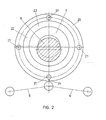
- Fig. 2 shows a first setting of the eccentric shaft for breaking soft rock
- Fig. 3 shows a medium setting for average rock conditions
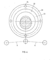
- Fig. 4 shows a further adjustment of the eccentric shaft to reduce the stroke and thus to transmit larger forces to the movable crushing jaw .
- a double toggle jaw crusher 1 is shown, on the housing 2, a bearing 3 for a bearing axis 4 is fixed.
- a movable crushing jaw 5 is swingingly suspended on the bearing axis 4 and is driven by toggle lever 6 via an eccentric shaft 7.
- the toggle lever 6 are hiebei of a exzentri the - at least partially encompassing the bearing shell's shaft stubs 8, wherein said transfer member is indicated by 9 and is supported against a fixed compression spring 10 degrees.
- the toggle levers 6 are moved alternately into a more extended and an angled position, which results in a stroke of the crushing jaw 5 in the direction of the double arrow 11.
- the breaker gap 12 can be adjusted by appropriate adjustment of the stationary counter jaw 13.
- the crushing jaw 13 is fixed via a releasable pull rod 14 and spacer elements 15 can be interposed according to the desired breaker gap 12.
- the forces are supported in each case via spherical bearings 16 in the crusher housing.
- the crushing surfaces are equipped with correspondingly wear-resistant insert parts 17.
- a return spring 18 is provided, which is also supported on the housing 2.
- the wear surfaces 17 can be exchanged in a simple manner and the fixing of one of the two wear surfaces is indicated schematically by a pull rod 19.
- a rotatable disk 20 is secured to the housing in the respective rotational position, for which purpose bores 21 are provided on the circumference of the disk.
- the rotatable disc 20 has an eccentric bore 22 for receiving the bearing body 23 of the eccentric shaft 7.
- a bearing body eccentricity which overall leads to a large stroke of the schematically indicated toggle levers 6. Such a large stroke naturally transmits smaller forces and is particularly suitable for breaking soft rock.
Landscapes
- Engineering & Computer Science (AREA)
- Mechanical Engineering (AREA)
- Food Science & Technology (AREA)
- Crushing And Grinding (AREA)
- Saccharide Compounds (AREA)
- Pharmaceuticals Containing Other Organic And Inorganic Compounds (AREA)
Abstract
Description
- Die Erfindung bezieht sich auf einen Backenbrecher mit einer ortsfest abgestützten Backe und einer relativ zu dieser Backe um eine Schwenkachse zu hin-und hergehender Bewegung antreibbaren Gegenbacke, bei welchem die antreibbare Gegenbacke über Kniehebel von einer Exzenterwelle bewegt wird.
- Mit derartigen Backenbrechern, welche als Kniehebel oder Doppelschwingenbrecher zum Stand der Technik zählen, können mittlere und große Gesteinsstücke auf einfache und wirkungsvolle Art maschinell zerkleinert werden. Die Verwendung von Kniehebeln zum Antrieb erlaubt es die bewegliche Backe geschwungen auszubilden und bei relativ hoch und nahe der Symmetrielinie des Brechwinkels gelegenem Gelenkpunkt mit einem Minimum an Reibung während des Brechvorganges sowie einem großen Hub im Bereich des Brechmauls zu arbeiten. Auf diese Weise wird der Flächenverschleiß vergleichmäßigt und der Brechbackenverschleiß vermindert. Auch kann die Schwerpunktlage der Schwinge so gewählt werden, daß die erforderliche Leerlaufleistung verringert wird. Durch geeignete Wahl des Drehpunktes läßt sich die Druckkomponente in der Weise einstellen, daß sie nach unten gerichtet ist, wodurch ein gutes Einziehen des zu brechenden Gesteines bewirkt wird und die Durchsatzleistung erhöht wird. Die günstige und gleichbleibende Kinematik ermöglicht die Annäherung an einen gestreckten Kniehebel und damit verbunden hohe Brechkräfte bei geringer Antriebsleistung, wodurch sich auch Vorteile für die Auslegung des Überlastschutzes ergeben. Durch diese Konstruktion wird auch ein gleichbleibender Hub der Brechschwinge und damit eine konstante Rückholfedereinstellung bewirkt. Der gesamte Kniehebelmechanismus kann mit einer geschlossenen Ölumlaufschmierung ausgebildet werden, wodurch sich die Lagerreibung verringern läßt und wiederum Antriebsleistung eingespart werden kann. Konstruktionsbedingt können leichte Kurbeltriebe verwendet werden, welche gleichzeitig zu einer Reduktion der dynamischen Kräfte auf das Fundament führen.
- Mit den bekannten Konstruktionen der eingangs genannten Art ist es jedoch nicht möglich die Kinematik des Antriebes gezielt zu verändern und damit den Hub und die Brechkräfte zu beeinflussen. Die bekannten Konstruktionen waren somit konstruktionsbedingt für bestimmte Gesteinsbeschaffenheit ausgelegt.
- Die Erfindung zielt nun darauf ab, bei einer derartigen bekannten Konstruktion in besonders einfacher Weise den Hub und die Brechkräfte zu beeinflussen, um unterschiedlichen Gesteinsbeschaffenheiten mit der gleichen Backenbrecherkonstruktion Rechnung tragen zu können. Zur Lösung dieser Aufgabe besteht die erfindungsgemäße Ausbildung bei einem Backenbrecher der eingangs genannten Art darin, daß die Lagerung der Exzenterwelle verschieblich und in der Verschiebelage festlegbar ist. Auf diese Weise ist es möglich, die Kniehebel in eine mehr oder minder gestreckte Lage zu bewegen, wobei bei gestreckterer Lage der Kniehebel der Hub relativ klein ist. Bei relativ kleinem Hub sind die Kräfte entsprechend größer und der Brecher ist in vorteilhafter Weise für hartes und sprödes Gestein geeignet. Die Spaltbreite muß lediglich durch entsprechende Justierung der ortsfesten Gegenbacke den jeweiligen Verhältnissen wieder angepaßt werden.
- Ebenso ist es durch Vergrößerung des Hubes bei entsprechend gewinkelter Lage der Kniehebel möglich kleinere Kräfte einzubringen. Diese Antriebskinematik ist für weiches Gestein besser geeignet.
- In besonders einfacher Weise kann die erfindungsgemäße Ausbildung so getroffen sein, daß die Lagerung der Exzenterwelle exzentrisch an einer drehbaren Kreisscheibe festgelegt ist. Mit Vorteil ist hiebei die Exzentrizität des Lagerkörpers so bemessen, so sie 10 bis 40 % der Exzentrizität der Antriebswelle beträgt.
- Der Antrieb der Exzenterwelle kann in einfacher Weise dadurch sichergestellt werden, daß die Exzenterwelle die Kreisscheibe durchsetzt und eine Riemenscheibe für den Antrieb trägt. Mit Vorteil ist hiebei für die verschiedenen Einstellungen des Lagerkörperexzenters bzw. der Kreisscheibe der Antriebsmotor der Exzenterwelle relativ zur Achse der Exzenterwelle verstellbar.
- Eine konstruktiv besonders einfache Ausgestaltung ergibt sich, wenn die Kreisscheibe an ihrem Umfang Bohrungen für die Festlegung der Drehlage durch Bolzen bzw. Schrauben aufweist.
- Bei einer Verstellung der Exzentrizität der Lagerung der Antriebswelle ergibt sich naturgemäß auch eine Veränderung der Spaltbreite des Backenbrechers. Es muß somit zumeist in der Folge in Anpassung an das jeweils zu brechende Gestein die feststehende Backe neu justiert werden.
- Die Erfindung wird nachfolgend an Hand eines in der Zeichnung dargestellten Ausführungsbeispieles näher erläutert. In dieser zeigen: Fig. 1 eine schematische Seitenansicht eines Doppelkniehebelbackenbrechers, Fig. 2 eine erste Einstellung der Exzenterwelle für das Brechen von weichem Gestein, Fig. 3 eine mittlere Einstellung für durchschnittliche Gesteinsbeschaffenheiten und Fig. 4 eine weitere Verstellung der Exzenterwelle zur Verringerung des Hubes und damit zur Übertragung größerer Kräfte auf die bewegliche Brechbacke.
- In Fig. 1 ist ein Doppelkniehebelbackenbrecher 1 dargestellt, an dessen Gehäuse 2 eine Lagerung 3 für eine Lagerachse 4 festgelegt ist. An der Lagerachse 4 ist schwingend eine bewegliche Brechbacke 5 aufgehängt, deren Antrieb durch Kniehebel 6 über eine Exzenterwelle 7 erfolgt. Die Kniehebel 6 werden hiebei von einer den exzentri- schen Wellenstummel 8 zumindest teilweise umgreifenden Lagerschale aufgenommen, wobei das Übertragungselement mit 9 bezeichnet ist und gegen eine ortsfeste Druckfeder 10 abgestützt ist. Durch Drehung der Exzenterwelle 7 werden die Kniehebel 6 abwechselnd in eine gestrecktere und eine abgewinkeltere Lage bewegt, wodurch sich ein Hub der Brechbacke 5 im Sinne des Doppelpfeiles 11 ergibt. Der Brecherspalt 12 kann durch entsprechende Justierung der ortsfesten Gegenbacke 13 eingestelt werden. Zu diesem Zweck ist die Brechbacke 13 über eine lösbare Zugstange 14 festgelegt und es können Distanzelemente 15 entsprechend dem gewünschten Brecherspalt 12 zwischengelegt werden. Die Abstützung der Kräfte erfolgt jeweils über ballige Lager 16 in das Brechergehäuse. Die- Brechflächen sind mit entsprechend verschleißfesten Einsatzteilen 17 ausgestattet.
- Zur Erzielung eines dauernden Kraftschlusses der beweglichen Backe 5 gegen die Kniehebel 6 ist eine Rückholfeder 18 vorgesehen, welche gleichfalls am Gehäuse 2 abgestützt ist. Die Verschleißflächen 17 können in einfacher Weise ausgetauscht werden und die Festlegung einer der beiden Verschleißflächen ist schematisch durch eine Zugstange 19 angedeutet.
- Bei der Ausbildung nach Fig. 2 ist die Lagerung der Exzenterwelle 7 vergrößert dargestellt. Am Gehäuse ist eine drehbare Scheibe 20 in der jeweiligen Drehlage gesichert festgelegt, wofür Bohrungen 21 am Umfang der Scheibe vorgesehen sind. Die drehbare Scheibe 20 weist eine exzentrische Bohrung 22 für die Aufnahme des Lagerkörpers 23 der Exzenterwelle 7 auf. Bei der in Fig. 2 dargestellten Drehlage, bei welcher eine Drehlagenmarkierung 24 in der unteren Stellung ersichtlich ist, ergibt sich zuzüglich zu der Exzentrizität der Antriebswelle 7 eine Lagerkörperexzentrizität, welche insgesamt zu einem großen Hub der schematisch angedeuteten Kniehebel 6 führt. Ein derartig großer Hub überträgt naturgemäß kleinere Kräfte und ist für das Brechen von weichem Gestein besonders geeignet. Durch Verdrehen der Drehscheibe 20 in die in Fig. 3 dargestellte Stellung, bei welcher die Markierung 24 nunmehr am linken Rande aufscheint, verringert sich auf Grund der Exzentrizität des Lagerkörpers der Hub der Kniehebel 6, so daß größere Kräfte übertragen werden können. Die größte Verringerung des Hubes der Kniehebel 6 wird dadurch erreicht, daß die Drehscheibe 20 in die in Fig. 4 dargestellte Position verdreht wird und in dieser Position festgelegt wird. In dieser Position erscheint die Markierung 24 oben und auf Grund der Exzentrizität der Lagerung des Lagerkörpers 23 ergibt sich in dieser Stellung der geringste Hub der Kniehebel 6 und damit die größte mögliche Brechkraftübertragung. Diese Einstellung ist besonders für hartes und sprödes Gestein geeignet
- Neben der in den Fig. 2 bis 4 dargestellten Verstellung des Hubes der Kniehebel 6 unter Verwendung einer Exzenterscheibe 20 für die Lagerung der Exzenterwelle 7 lassen sich naturgemäß auch andere Verstellungen, beispielsweise eine Spindelverstellung des Lagerkörpers 23 realisieren, die dargestellte Exzenterscheibe bietet jedoch konstruktiv den geringsten Aufwand bei gleichzeitig maximaler Stabilität und einfacher Verstellbarkeit.
Claims (6)
Applications Claiming Priority (2)
| Application Number | Priority Date | Filing Date | Title |
|---|---|---|---|
| AT1423/85 | 1985-05-10 | ||
| AT1423/85A AT393233B (de) | 1985-05-10 | 1985-05-10 | Backenbrecher |
Publications (3)
| Publication Number | Publication Date |
|---|---|
| EP0201477A2 true EP0201477A2 (de) | 1986-11-12 |
| EP0201477A3 EP0201477A3 (en) | 1987-10-14 |
| EP0201477B1 EP0201477B1 (de) | 1990-07-18 |
Family
ID=3513575
Family Applications (1)
| Application Number | Title | Priority Date | Filing Date |
|---|---|---|---|
| EP86890122A Expired - Lifetime EP0201477B1 (de) | 1985-05-10 | 1986-04-29 | Backenbrecher |
Country Status (3)
| Country | Link |
|---|---|
| EP (1) | EP0201477B1 (de) |
| AT (2) | AT393233B (de) |
| DE (1) | DE3672681D1 (de) |
Cited By (8)
| Publication number | Priority date | Publication date | Assignee | Title |
|---|---|---|---|---|
| EP0259296A3 (de) * | 1986-09-02 | 1988-06-08 | VOEST-ALPINE Aktiengesellschaft | Backenbrecher |
| WO1995027111A1 (en) * | 1994-03-30 | 1995-10-12 | Machinefabriek Lubo B.V. | Continuously operating (hydraulic) crusher for pulverizing among other things stone, concrete, asphalt parts and the like, mountable to a hydraulic excavator |
| ITMI20091787A1 (it) * | 2009-10-16 | 2011-04-17 | Rimac Evolution S R L | Frantoio per la frantumazione di materiale inerte, con mezzi automatici per la regolazione della pezzatura del materiale frantumato. |
| US8322643B2 (en) | 2010-07-23 | 2012-12-04 | Mining Technologies International Inc. | Rock crusher attachment |
| CN107810062A (zh) * | 2015-06-25 | 2018-03-16 | 山特维克知识产权股份有限公司 | 偏心破碎颚安装组件 |
| WO2018192706A1 (de) | 2017-04-21 | 2018-10-25 | Kleemann Gmbh | Brecherbaugruppe fuer einen backenbrecher |
| CN114558679A (zh) * | 2022-03-17 | 2022-05-31 | 中国铁建重工集团股份有限公司 | 一种破碎装置 |
| CN117380306A (zh) * | 2023-12-05 | 2024-01-12 | 江西杰斯凯矿山机械有限公司 | 一种矿石开采加工用颚式破碎机 |
Family Cites Families (5)
| Publication number | Priority date | Publication date | Assignee | Title |
|---|---|---|---|---|
| US1491430A (en) * | 1922-06-09 | 1924-04-22 | Albert H Stebbins | Crusher |
| GB394913A (en) * | 1932-03-11 | 1933-07-06 | Krupp Fried Grusonwerk Ag | Improvements in or relating to stone crushers |
| US2235097A (en) * | 1937-11-05 | 1941-03-18 | Benson Albert Thomas | Rock crusher |
| US3425639A (en) * | 1966-05-25 | 1969-02-04 | Don Kueneman | Jaw crushers |
| AT327655B (de) * | 1974-03-12 | 1976-02-10 | Dobrowsky Josef Dipl Ing | Backenbrecher |
-
1985
- 1985-05-10 AT AT1423/85A patent/AT393233B/de not_active IP Right Cessation
-
1986
- 1986-04-29 EP EP86890122A patent/EP0201477B1/de not_active Expired - Lifetime
- 1986-04-29 AT AT86890122T patent/ATE54581T1/de active
- 1986-04-29 DE DE8686890122T patent/DE3672681D1/de not_active Expired - Fee Related
Cited By (13)
| Publication number | Priority date | Publication date | Assignee | Title |
|---|---|---|---|---|
| EP0259296A3 (de) * | 1986-09-02 | 1988-06-08 | VOEST-ALPINE Aktiengesellschaft | Backenbrecher |
| WO1995027111A1 (en) * | 1994-03-30 | 1995-10-12 | Machinefabriek Lubo B.V. | Continuously operating (hydraulic) crusher for pulverizing among other things stone, concrete, asphalt parts and the like, mountable to a hydraulic excavator |
| ITMI20091787A1 (it) * | 2009-10-16 | 2011-04-17 | Rimac Evolution S R L | Frantoio per la frantumazione di materiale inerte, con mezzi automatici per la regolazione della pezzatura del materiale frantumato. |
| US8322643B2 (en) | 2010-07-23 | 2012-12-04 | Mining Technologies International Inc. | Rock crusher attachment |
| CN107810062A (zh) * | 2015-06-25 | 2018-03-16 | 山特维克知识产权股份有限公司 | 偏心破碎颚安装组件 |
| CN110461476A (zh) * | 2017-04-21 | 2019-11-15 | 克磊镘有限公司 | 用于颚式破碎机的破碎机组件 |
| WO2018192706A1 (de) | 2017-04-21 | 2018-10-25 | Kleemann Gmbh | Brecherbaugruppe fuer einen backenbrecher |
| CN110461476B (zh) * | 2017-04-21 | 2021-11-26 | 克磊镘有限公司 | 用于颚式破碎机的破碎机组件 |
| US11583864B2 (en) | 2017-04-21 | 2023-02-21 | Kleemann Gmbh | Crusher assembly for a jaw crusher |
| CN114558679A (zh) * | 2022-03-17 | 2022-05-31 | 中国铁建重工集团股份有限公司 | 一种破碎装置 |
| CN114558679B (zh) * | 2022-03-17 | 2023-06-23 | 中国铁建重工集团股份有限公司 | 一种破碎装置 |
| CN117380306A (zh) * | 2023-12-05 | 2024-01-12 | 江西杰斯凯矿山机械有限公司 | 一种矿石开采加工用颚式破碎机 |
| CN117380306B (zh) * | 2023-12-05 | 2024-02-02 | 江西杰斯凯矿山机械有限公司 | 一种矿石开采加工用颚式破碎机 |
Also Published As
| Publication number | Publication date |
|---|---|
| EP0201477A3 (en) | 1987-10-14 |
| DE3672681D1 (de) | 1990-08-23 |
| ATA142385A (de) | 1991-02-15 |
| AT393233B (de) | 1991-09-10 |
| ATE54581T1 (de) | 1990-08-15 |
| EP0201477B1 (de) | 1990-07-18 |
Similar Documents
| Publication | Publication Date | Title |
|---|---|---|
| DE3744862C2 (de) | Schneidkopf zum Schneiden von Flachmaterial mit Messerschleifmechanismus | |
| EP0615483B1 (de) | Exzentertellerschleifer | |
| DE69615781T2 (de) | Verfahren zum Betrieb eines Exzenterbackenbrechers | |
| EP0911125B1 (de) | Hochgeschwindigkeitsschere zum Querteilen von Walzband | |
| DE69611636T2 (de) | Schervorrichtung, besonders zum Schneiden von Metallen oder Beton | |
| DE4231479A1 (de) | Abschervorrichtung | |
| DE3022493A1 (de) | Motorbetriebene stossaege mit langgestrecktem saegeblatt | |
| DE602004008336T2 (de) | Vorrichtung zum schärfen von kettensägezähnen | |
| EP0201477B1 (de) | Backenbrecher | |
| DE2704243A1 (de) | Walzenmuehle | |
| DE1252044B (de) | ||
| DE2730166C3 (de) | Walzenstuhl für die Vermahlung und Schrotung von Getreide | |
| EP1811194B1 (de) | Scheibenbremse | |
| EP2366482A1 (de) | Mehrachsiger Vorritzer | |
| DE69521584T2 (de) | Einstellvorrichtung für den kniegelenkblock eines backenbrechers, und verwendung dieser vorrichtung | |
| EP0370258B1 (de) | Einrichtung zum oszillierenden Antreiben mindestens einer Welle und eine Vorrichtung zum schrittweisen Vorschieben eines Werkstückes mit der Einrichtung | |
| DE2838782A1 (de) | Walzenmuehle mit hydropneumatischer federung | |
| DE10206709A1 (de) | Backenbrecher | |
| DE2355899A1 (de) | Maulbrecher | |
| DE2840465C2 (de) | ||
| EP0881047A2 (de) | Antriebseinrichtung für eine schnellaufende Stanz- und Schneidpresse | |
| EP0259296A2 (de) | Backenbrecher | |
| CH638720A5 (de) | Presse. | |
| EP0444019B1 (de) | Backenbrecher | |
| DE3825716A1 (de) | Walzenmuehle |
Legal Events
| Date | Code | Title | Description |
|---|---|---|---|
| PUAI | Public reference made under article 153(3) epc to a published international application that has entered the european phase |
Free format text: ORIGINAL CODE: 0009012 |
|
| AK | Designated contracting states |
Kind code of ref document: A2 Designated state(s): AT BE CH DE FR GB IT LI LU NL SE |
|
| PUAB | Information related to the publication of an a document modified or deleted |
Free format text: ORIGINAL CODE: 0009199EPPU |
|
| RA1 | Application published (corrected) |
Date of ref document: 19861217 Kind code of ref document: A2 |
|
| PUAL | Search report despatched |
Free format text: ORIGINAL CODE: 0009013 |
|
| AK | Designated contracting states |
Kind code of ref document: A3 Designated state(s): AT BE CH DE FR GB IT LI LU NL SE |
|
| RHK1 | Main classification (correction) |
Ipc: B02C 1/04 |
|
| 17P | Request for examination filed |
Effective date: 19880325 |
|
| 17Q | First examination report despatched |
Effective date: 19890208 |
|
| GRAA | (expected) grant |
Free format text: ORIGINAL CODE: 0009210 |
|
| AK | Designated contracting states |
Kind code of ref document: B1 Designated state(s): AT BE CH DE FR GB IT LI LU NL SE |
|
| PG25 | Lapsed in a contracting state [announced via postgrant information from national office to epo] |
Ref country code: NL Effective date: 19900718 |
|
| REF | Corresponds to: |
Ref document number: 54581 Country of ref document: AT Date of ref document: 19900815 Kind code of ref document: T |
|
| ET | Fr: translation filed | ||
| RAP2 | Party data changed (patent owner data changed or rights of a patent transferred) |
Owner name: MASCHINENFABRIK LIEZEN GESELLSCHAFT M.B.H. |
|
| REF | Corresponds to: |
Ref document number: 3672681 Country of ref document: DE Date of ref document: 19900823 |
|
| ITF | It: translation for a ep patent filed | ||
| GBT | Gb: translation of ep patent filed (gb section 77(6)(a)/1977) | ||
| BECN | Be: change of holder's name |
Effective date: 19900718 |
|
| NLV1 | Nl: lapsed or annulled due to failure to fulfill the requirements of art. 29p and 29m of the patents act | ||
| PGFP | Annual fee paid to national office [announced via postgrant information from national office to epo] |
Ref country code: LU Payment date: 19910328 Year of fee payment: 6 |
|
| PLBE | No opposition filed within time limit |
Free format text: ORIGINAL CODE: 0009261 |
|
| STAA | Information on the status of an ep patent application or granted ep patent |
Free format text: STATUS: NO OPPOSITION FILED WITHIN TIME LIMIT |
|
| 26N | No opposition filed | ||
| EPTA | Lu: last paid annual fee | ||
| PG25 | Lapsed in a contracting state [announced via postgrant information from national office to epo] |
Ref country code: LU Free format text: LAPSE BECAUSE OF NON-PAYMENT OF DUE FEES Effective date: 19920429 |
|
| ITTA | It: last paid annual fee | ||
| EAL | Se: european patent in force in sweden |
Ref document number: 86890122.4 |
|
| PGFP | Annual fee paid to national office [announced via postgrant information from national office to epo] |
Ref country code: DE Payment date: 19950315 Year of fee payment: 10 |
|
| PGFP | Annual fee paid to national office [announced via postgrant information from national office to epo] |
Ref country code: CH Payment date: 19950316 Year of fee payment: 10 |
|
| PGFP | Annual fee paid to national office [announced via postgrant information from national office to epo] |
Ref country code: FR Payment date: 19950320 Year of fee payment: 10 Ref country code: BE Payment date: 19950320 Year of fee payment: 10 Ref country code: GB Payment date: 19950320 Year of fee payment: 10 |
|
| PGFP | Annual fee paid to national office [announced via postgrant information from national office to epo] |
Ref country code: AT Payment date: 19950321 Year of fee payment: 10 |
|
| PGFP | Annual fee paid to national office [announced via postgrant information from national office to epo] |
Ref country code: SE Payment date: 19950322 Year of fee payment: 10 |
|
| PG25 | Lapsed in a contracting state [announced via postgrant information from national office to epo] |
Ref country code: GB Effective date: 19960429 Ref country code: AT Effective date: 19960429 |
|
| PG25 | Lapsed in a contracting state [announced via postgrant information from national office to epo] |
Ref country code: SE Effective date: 19960430 Ref country code: LI Effective date: 19960430 Ref country code: CH Effective date: 19960430 Ref country code: BE Effective date: 19960430 |
|
| BERE | Be: lapsed |
Owner name: MASCHINENFABRIK LIEZEN G.M.B.H. Effective date: 19960430 |
|
| REG | Reference to a national code |
Ref country code: CH Ref legal event code: PL |
|
| GBPC | Gb: european patent ceased through non-payment of renewal fee |
Effective date: 19960429 |
|
| PG25 | Lapsed in a contracting state [announced via postgrant information from national office to epo] |
Ref country code: FR Effective date: 19961227 |
|
| PG25 | Lapsed in a contracting state [announced via postgrant information from national office to epo] |
Ref country code: DE Effective date: 19970101 |
|
| EUG | Se: european patent has lapsed |
Ref document number: 86890122.4 |
|
| REG | Reference to a national code |
Ref country code: FR Ref legal event code: ST |
|
| PG25 | Lapsed in a contracting state [announced via postgrant information from national office to epo] |
Ref country code: IT Free format text: LAPSE BECAUSE OF NON-PAYMENT OF DUE FEES Effective date: 20050429 |