EP0200094B1 - Rundstrickmaschine - Google Patents
Rundstrickmaschine Download PDFInfo
- Publication number
- EP0200094B1 EP0200094B1 EP86105254A EP86105254A EP0200094B1 EP 0200094 B1 EP0200094 B1 EP 0200094B1 EP 86105254 A EP86105254 A EP 86105254A EP 86105254 A EP86105254 A EP 86105254A EP 0200094 B1 EP0200094 B1 EP 0200094B1
- Authority
- EP
- European Patent Office
- Prior art keywords
- cylinder
- circular knitting
- needles
- knitting machine
- drive
- Prior art date
- Legal status (The legal status is an assumption and is not a legal conclusion. Google has not performed a legal analysis and makes no representation as to the accuracy of the status listed.)
- Expired
Links
- 238000009940 knitting Methods 0.000 title claims abstract description 11
- 239000000969 carrier Substances 0.000 description 3
- 210000002105 tongue Anatomy 0.000 description 3
- 238000010276 construction Methods 0.000 description 2
- 239000004744 fabric Substances 0.000 description 2
- 244000089486 Phragmites australis subsp australis Species 0.000 description 1
- 230000000630 rising effect Effects 0.000 description 1
Images

Classifications
-
- D—TEXTILES; PAPER
- D04—BRAIDING; LACE-MAKING; KNITTING; TRIMMINGS; NON-WOVEN FABRICS
- D04B—KNITTING
- D04B25/00—Warp knitting machines not otherwise provided for
- D04B25/02—Tubular machines
Definitions
- the invention relates to a circular knitting machine with a set of latch needles, which are arranged around a cylinder, and with a drive.
- the solution to this problem according to the invention is that the cylinder can be moved vertically up and down by the drive, while the set of needles remains at rest.
- the needles which in turn are of conventional construction and are arranged in a circle around a cylindrical tube or the cylinder, are stationary and the knitting is effected during an up and / or down movement of the tubular construction.
- One of the advantages achieved with circular knitting machines is an increase in the speed at which the goods are produced.
- there is a considerable saving on needles because the latter are less subject to wear, tearing and breaking.
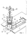
- a base plate 15 can be seen there, on which two leaf springs 8 are arranged one above the other at a distance from one another and are held at one end by blocks 8 '.
- the opposite end of the leaf springs 8 is attached to a cylindrical tube or cylinder 5 in a manner to be described.
- This cylinder 5 is mounted on an annular element 6 which, for practical reasons, is composed of two semicircular parts.
- the element 6 extends with a part of its circumference into the gap between the two leaf springs 8 and is firmly attached to it with screw bolts 6 'and 9.
- the two halves of the element 6 are interconnected by screws 7, of which only one can be seen in the figure.
- the cylinder 5 carries a needle bed 1, the needles 2 being arranged in the spaces between the individual members thereof, only a few of which can be seen in the drawing for the sake of clarity.
- the needle bed 1 is held in two ring elements 3, 4 which are screwed onto a cover plate covering the springs 8.
- a thread carrier with a circular flange plate 11 is arranged above the needles 2, which extend upward from the needle bed 1.
- An arm cross 10 with a circular cylindrical bore is fastened to the flange thereof, through which a shaft 11 'passes, which can be rotated in a sleeve 10' rising from the arm cross 10.
- the shaft 11 ' carries a radially extending lever 13 near its head, while a similar lever 12 is attached to the sleeve 10'.
- the movement of the thread carrier is derived from these levers 12, 13, which are actuated by cam disks.
- the relevant cam not shown, moves the lever 12 oscillating through an angle, so that the thread carrier is rotated from one needle to the next.
- the function of the machine is as follows:
- the thread is fed to the machine from conventional conical bobbins, which are held in a bobbin case as usual, and reaches the thread carriers 10, 11 under tension.
- the thread carriers have bores, which are represented in the drawings by dots; according to the respective individual thread length, several holes are led to each needle 1, d. H. as many as there are needles in individual cases.
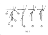
- the thread carriers 10, 11 move horizontally and insert the thread into the needle heads when the loops formed have passed the tongues, as can be derived from FIGS. 3 (A, B, C, D).
- FIGS. 3 A, B, C, D
- Position C shows that the cylinder 5 moves with the fabric upwards, so that the stitch closes the needle tongue and falls into the knitted fabric.
- the cylinder 5 moves up to the knock-off position in order to form the new stitch through the previous one. Whenever the cylinder 5 lifts, the stitch formed is withdrawn from the needle 1 and a new stitch is formed, which is continued as long as the thread is fed to the machine.
- the up and down movement of the cylinder 5 is effected by a cam disk, the cylinder 5 being held by a pair of flat springs 8, as has already been mentioned.
Landscapes
- Engineering & Computer Science (AREA)
- Textile Engineering (AREA)
- Knitting Machines (AREA)
- Massaging Devices (AREA)
Description
- Die Erfindung betrifft eine Rundstrickmaschine mit einem Satz von Zungennadeln, die um einen Zylinder herum angeordnet sind, und mit einem Antrieb.
- Bei aus der Praxis bekannten Maschinen dieser Art (siehe GB-A-192717) bewegt sich der Satz Nadeln nach oben, so wie sich die Ware vorbewegt. Die Erfindung möchte bestimmte Verbesserungen an Rundstrickmaschinen der eingangs genannten Art erreichen.
- Es besteht daher die Aufgabe, sowohl den Aufbau als auch die Arbeitsweise von Rundstrickmaschinen zu vereinfachen.
- Die erfindungsgemäße Lösung dieser Aufgabe besteht darin, daß der Zylinder durch den Antrieb vertikal auf- und abbewegbar ist, während der Satz Nadeln in Ruhe verbleibt.
- Bei der erfindungsgemäßen Rundstrickmaschine sind also die Nadeln, die ihrerseits von üblichem Aufbau und auf einem Kreis um ein zylindrisches Rohr bzw. den Zylinder herum angeordnet sind, stationär und wird das Stricken während einer Auf- und/oder Abbewegung der rohrförmigen Konstruktion bewirkt. Einer der hierdurch bei Rundstrickmaschinen erreichten Vorteile besteht in einer Vergrößerung der Geschwindigkeit, mit der die Ware erzeugt wird. Hinzu kommt eine beachtliche Ersparnis an Nadeln, weil letztere einem geringeren Abnutzen, Reißen und Brechen unterworfen sind.
- Im folgenden werden die Erfindung und vorteilhafte Ausgestaltungen derselben anhand einer Zeichnung ausführlich erläutert. Es zeigen
- Fig. 1 in einer schematischen, teilweise geschnittenen Sicht die Hauptteile einer Rundstrickmaschine, wobei einige übliche Teile, wie Abdeckungen und Gehäuse, aus Gründen der Klarheit weggelassen worden sind,
- Fig. 2 eine auseinandergezogene Darstellung der Maschinenteile gemäß Fig. 1 und
- Fig. 3 (A, B, C, D) die verschiedenen Stellungen des inneren Rohres relativ zu den Nadeln.
- Wendet man sich zunächst der Fig. 1 zu, so ist dort eine Grundplatte 15 zu erkennen, auf der mit Abstand voneinander zwei Blattfedern 8 übereinander angeordnet sind, die an ihrem einen Ende klemmend durch Blöcke 8' gehalten sind. Das gegenüberliegende Ende der Blattfedern 8 ist in einer noch zu beschreibenden Art und Weise an einem zylinderischen Rohr bzw. Zylinder 5 befestigt. Dieser Zylinder 5 ist auf einem ringförmigen Element 6 montiert, das aus praktischen Gründen aus zwei halbkreisförmigen Teilen zusammengesetzt ist. Das Element 6 erstreckt sich mit einem Teil seines Umfanges in den Spalt zwischen den beiden Blattfedern 8 und ist mit Schraubenbolzen 6' und 9 fest daran befestigt. Die zwei Hälften des Elementes 6 sind untereinander durch Schrauben 7 miteinander verbunden, von denen in der Figur nur eine zu erkennen ist.
- Der Zylinder 5 trägt ein Nadelbett 1, wobei in den Zwischenräumen zwischen den Einzelgliedem desselben die Nadeln 2 angeordnet sind, von denen in der Zeichnung aus Gründen der Klarheit nur einige zu sehen sind. Das Nadelbett 1 ist in zwei Ringelementen 3, 4 gehalten, die auf eine die Federn 8 bedeckende Deckplatte geschraubt sind.
- Oberhalb der Nadeln 2, die sich vom Nadelbett 1 nach oben erstrecken, ist ein Fadenträger mit einer kreisförmigen Flanschplatte 11 angeordnet. An deren Flansch ist ein Armkreuz 10 mit einer kreiszylindrischen Bohrung befestigt, durch welche ein Schaft 11' hindurchgeht, der in einer sich vom Armkreuz 10 erhebenden Hülse 10' drehbar ist. Der Schaft 11' trägt nahe seines Kopfes einen sich radial erstreckenden Hebel 13, während an der Hüse 10' ein ähnlicher Hebel 12 befestigt ist. Die Bewegung des Fadenträgers ist von diesen Hebeln 12, 13 abgeleitet, die durch Nockenscheiben betätigt sind. Die betreffende, nicht dargestellte Nockenscheibe bewegt den Hebel 12 um einen Winkel oszillierend, so daß der Fadenträger von einer Nadel zur nächsten gedreht wird.
- Die Funktion der Maschine ist wie folgt : Der Faden wird der Maschine von üblichen konischen Spulen zugeführt, die wie üblich in einem Spulengehäuse gehalten sind, und erreicht die Fadenträger 10, 11 unter Spannung. Die Fadenträger weisen Bohrungen auf, die in den Zeichnungen durch Punkte dargestellt sind ; entsprechend der jeweiligen individuellen Fadenlänge sind mehrere Bohrungen zu jeder Nadel 1 geführt, d. h. soviele, wie im Einzelfall Nadeln vorhanden sind. Die Fadenträger 10, 11 bewegen sich horizontal und setzen den Faden in die Nadelköpfe ein, wenn die gebildeten Schlaufen die Zungen passiert haben, wie es aus den Figuren 3 (A, B, C, D) abgeleitet werden kann. In der in Fig. 3A dargestellten Stellung befindet sich das innere Rohr bzw. der Zylinder 5 in einer Zwischenstellung. In Stellung B bewegt sich der Zylinder 5 nach unten, um die Zunge der Nadel 1 freizumachen. In diesem Moment bewegen sich die Fadenzuführer 10, 11 seitlich, um den Faden in den Haken der Nadel einzulegen. Stellung C zeigt, daß sich der Zylinder 5 mit der Ware nach oben bewegt, so daß die Masche die Nadelzunge schließt und in die Strickware fällt. Als letztes bewegt sich entsprechend Fig. 3D der Zylinder 5 nach oben in die Abschlagstellung, um die neue Masche durch die vorherige hindurch zu bilden. Immer dann, wenn sich der Zylinder 5 hebt, wird die gebildete Masche von der Nadel 1 abgezogen und eine neue Masche gebildet, was solange forgeführt wird, wie der Faden der Maschine zugeführt wird.
- Die Auf- und Abbewegung des Zylinders 5 wird durch eine Nockenscheibe bewirkt, wobei der Zylinder 5, wie schon erwähnt worden ist, durch ein Paar flache Federn 8 gehalten ist.
Claims (2)
Priority Applications (1)
| Application Number | Priority Date | Filing Date | Title |
|---|---|---|---|
| AT86105254T ATE44293T1 (de) | 1985-05-02 | 1986-04-16 | Rundstrickmaschine. |
Applications Claiming Priority (2)
| Application Number | Priority Date | Filing Date | Title |
|---|---|---|---|
| IL75074A IL75074A (en) | 1985-05-02 | 1985-05-02 | Circular knitting machines |
| IL75074 | 1985-05-02 |
Publications (2)
| Publication Number | Publication Date |
|---|---|
| EP0200094A1 EP0200094A1 (de) | 1986-11-05 |
| EP0200094B1 true EP0200094B1 (de) | 1989-06-28 |
Family
ID=11055869
Family Applications (1)
| Application Number | Title | Priority Date | Filing Date |
|---|---|---|---|
| EP86105254A Expired EP0200094B1 (de) | 1985-05-02 | 1986-04-16 | Rundstrickmaschine |
Country Status (4)
| Country | Link |
|---|---|
| EP (1) | EP0200094B1 (de) |
| AT (1) | ATE44293T1 (de) |
| DE (1) | DE3664140D1 (de) |
| IL (1) | IL75074A (de) |
Families Citing this family (1)
| Publication number | Priority date | Publication date | Assignee | Title |
|---|---|---|---|---|
| DE3813011A1 (de) * | 1988-04-19 | 1989-11-02 | Textilmaschinenfabrik Harry Lu | Rundstrickmaschine zur herstellung einer raschelartigen schlauchware |
Family Cites Families (2)
| Publication number | Priority date | Publication date | Assignee | Title |
|---|---|---|---|---|
| FR519751A (fr) * | 1919-12-04 | 1921-06-15 | Marius Ratignier | Métier à fabriquer les tissus à mailles |
| CH143965A (fr) * | 1929-09-14 | 1930-12-15 | Friedrich Wagner Gottlob | Métier à chaîne circulaire. |
-
1985
- 1985-05-02 IL IL75074A patent/IL75074A/xx unknown
-
1986
- 1986-04-16 DE DE8686105254T patent/DE3664140D1/de not_active Expired
- 1986-04-16 AT AT86105254T patent/ATE44293T1/de active
- 1986-04-16 EP EP86105254A patent/EP0200094B1/de not_active Expired
Also Published As
| Publication number | Publication date |
|---|---|
| IL75074A (en) | 1988-08-31 |
| DE3664140D1 (en) | 1989-08-03 |
| ATE44293T1 (de) | 1989-07-15 |
| EP0200094A1 (de) | 1986-11-05 |
| IL75074A0 (en) | 1985-09-29 |
Similar Documents
| Publication | Publication Date | Title |
|---|---|---|
| DE69304124T2 (de) | Rundstrickmaschine mit mehreren Fadenzulieferstellen, insbesondere für Strümpfe | |
| DE4018829A1 (de) | Fadenschneidvorrichtung in einer stichbildenden maschine | |
| DE2427517A1 (de) | Vorrichtung zum wickeln von toroidablenkspulen | |
| EP0200094B1 (de) | Rundstrickmaschine | |
| DE3245230C2 (de) | Festigkeitsverstelleinrichtung an Flachstrickmaschinen | |
| DE3244946C1 (de) | Freiumlaufender Greifer fuer Doppelsteppstichnaehmaschinen | |
| DD284064A5 (de) | Strickmaschine | |
| DE2047081A1 (de) | Nahmaschine | |
| DE2415991C3 (de) | Fadenspannvorrichtung | |
| DE2025144A1 (en) | High-speed knitting machine | |
| DE3104298C2 (de) | ||
| DE1284023B (de) | Kettenwirkmaschine mit zwei Wirknadelfonturen | |
| DE69107053T2 (de) | Nadelauswahlvorrichtung für Rundstrickmaschine, insbesondere für Strümpfe. | |
| DE2613179A1 (de) | Nadel- und nadelbettanordnung an flach- und rundstrickmaschinen | |
| DE1072069B (de) | Nähmaschine | |
| DE349032C (de) | Rundstrickmaschine | |
| DE1485254C3 (de) | Haushaltnähmaschine mit Zickzack-Einrichtung | |
| CH671977A5 (de) | ||
| DE509831C (de) | Fadenspannvorrichtung fuer Rundstrickmaschinen | |
| DE3725171A1 (de) | Ringelvorrichtung fuer eine rundstrickmaschine | |
| DE2556579A1 (de) | Vorrichtung mit zwei durch verbindungsglieder voneinander abstehend gehaltenen teilen | |
| DE1281251B (de) | Zickzacknaehmaschine | |
| DE2109897A1 (de) | Führungsnockenanordnung für Strickmaschinen | |
| DE2644611A1 (de) | Steppmaschine | |
| DE2905108A1 (de) | Rundkettelmaschine |
Legal Events
| Date | Code | Title | Description |
|---|---|---|---|
| PUAI | Public reference made under article 153(3) epc to a published international application that has entered the european phase |
Free format text: ORIGINAL CODE: 0009012 |
|
| AK | Designated contracting states |
Kind code of ref document: A1 Designated state(s): AT BE CH DE FR GB IT LI LU NL SE |
|
| 17P | Request for examination filed |
Effective date: 19870415 |
|
| 17Q | First examination report despatched |
Effective date: 19880601 |
|
| GRAA | (expected) grant |
Free format text: ORIGINAL CODE: 0009210 |
|
| AK | Designated contracting states |
Kind code of ref document: B1 Designated state(s): AT BE CH DE FR GB IT LI LU NL SE |
|
| PG25 | Lapsed in a contracting state [announced via postgrant information from national office to epo] |
Ref country code: SE Effective date: 19890628 Ref country code: BE Effective date: 19890628 |
|
| REF | Corresponds to: |
Ref document number: 44293 Country of ref document: AT Date of ref document: 19890715 Kind code of ref document: T |
|
| REF | Corresponds to: |
Ref document number: 3664140 Country of ref document: DE Date of ref document: 19890803 |
|
| ITF | It: translation for a ep patent filed | ||
| PG25 | Lapsed in a contracting state [announced via postgrant information from national office to epo] |
Ref country code: GB Effective date: 19900416 Ref country code: AT Effective date: 19900416 |
|
| PG25 | Lapsed in a contracting state [announced via postgrant information from national office to epo] |
Ref country code: LU Free format text: LAPSE BECAUSE OF NON-PAYMENT OF DUE FEES Effective date: 19900430 Ref country code: LI Effective date: 19900430 Ref country code: CH Effective date: 19900430 |
|
| PLBE | No opposition filed within time limit |
Free format text: ORIGINAL CODE: 0009261 |
|
| STAA | Information on the status of an ep patent application or granted ep patent |
Free format text: STATUS: NO OPPOSITION FILED WITHIN TIME LIMIT |
|
| 26N | No opposition filed | ||
| PG25 | Lapsed in a contracting state [announced via postgrant information from national office to epo] |
Ref country code: NL Effective date: 19901101 |
|
| GBPC | Gb: european patent ceased through non-payment of renewal fee | ||
| NLV4 | Nl: lapsed or anulled due to non-payment of the annual fee | ||
| PG25 | Lapsed in a contracting state [announced via postgrant information from national office to epo] |
Ref country code: FR Effective date: 19901228 |
|
| REG | Reference to a national code |
Ref country code: CH Ref legal event code: PL |
|
| PG25 | Lapsed in a contracting state [announced via postgrant information from national office to epo] |
Ref country code: DE Effective date: 19910101 |
|
| REG | Reference to a national code |
Ref country code: FR Ref legal event code: ST |
|
| PG25 | Lapsed in a contracting state [announced via postgrant information from national office to epo] |
Ref country code: IT Free format text: LAPSE BECAUSE OF NON-PAYMENT OF DUE FEES;WARNING: LAPSES OF ITALIAN PATENTS WITH EFFECTIVE DATE BEFORE 2007 MAY HAVE OCCURRED AT ANY TIME BEFORE 2007. THE CORRECT EFFECTIVE DATE MAY BE DIFFERENT FROM THE ONE RECORDED. Effective date: 20050416 |