EP0193971B1 - Druckpolster-Überlastsicherung - Google Patents
Druckpolster-Überlastsicherung Download PDFInfo
- Publication number
- EP0193971B1 EP0193971B1 EP86103073A EP86103073A EP0193971B1 EP 0193971 B1 EP0193971 B1 EP 0193971B1 EP 86103073 A EP86103073 A EP 86103073A EP 86103073 A EP86103073 A EP 86103073A EP 0193971 B1 EP0193971 B1 EP 0193971B1
- Authority
- EP
- European Patent Office
- Prior art keywords
- valve
- piston
- valve body
- pressure
- pressure cushion
- Prior art date
- Legal status (The legal status is an assumption and is not a legal conclusion. Google has not performed a legal analysis and makes no representation as to the accuracy of the status listed.)
- Expired
Links
- 239000012530 fluid Substances 0.000 claims description 16
- 238000007789 sealing Methods 0.000 claims description 2
- 230000008878 coupling Effects 0.000 description 5
- 238000010168 coupling process Methods 0.000 description 5
- 238000005859 coupling reaction Methods 0.000 description 5
- 230000000903 blocking effect Effects 0.000 description 2
- 230000006835 compression Effects 0.000 description 2
- 238000007906 compression Methods 0.000 description 2
- 238000006073 displacement reaction Methods 0.000 description 2
- 239000007788 liquid Substances 0.000 description 1
- 230000002093 peripheral effect Effects 0.000 description 1
Images

Classifications
-
- B—PERFORMING OPERATIONS; TRANSPORTING
- B30—PRESSES
- B30B—PRESSES IN GENERAL
- B30B15/00—Details of, or accessories for, presses; Auxiliary measures in connection with pressing
- B30B15/28—Arrangements for preventing distortion of, or damage to, presses or parts thereof
- B30B15/281—Arrangements for preventing distortion of, or damage to, presses or parts thereof overload limiting devices
- B30B15/284—Arrangements for preventing distortion of, or damage to, presses or parts thereof overload limiting devices releasing fluid from a fluid chamber subjected to overload pressure
Definitions
- the invention relates to a device for the rapid leakage of a pressure pad overload safety device, in which a piston is pressed by the pressure pad pressure in a cylinder into the active position and shifts slightly from the active position in the event of overload, and in which an outlet valve is provided between the pressure pad and the outside, the The valve body is acted upon by the pressure cushion on one side and is supported on the side opposite the pressure cushion when the piston is in the operative position, wherein it is pressed into the valve seat in the blocking position.
- valve In a known (DE-B-2150 726) device of this type, the valve is provided on a line leading away from the pressure cushion and the valve body is supported by a spring on a stationary part.
- the valve body has a conical inner surface, of which only the tip area is constantly acted upon by the pressure cushion. In the event of an overload, the valve body is pushed back a little so that the entire inner surface of the valve body is acted upon, which suddenly brings the valve body into the open position.
- This device works time-consuming, because first the pressure belonging to the overload has to be built up, then a safety valve is actuated by pushing back the pointed area and then the actual drain valve is actuated.
- a device with an overload safety device is also known (GB-A-2 031 519), in which an outlet valve is arranged in a piston.
- the piston is a working piston, which serves to drive a plunger arranged in the working cylinder.
- the outlet valve is loaded on one side from the pressure chamber. It is assumed that it is a valve which is acted upon on the one hand by the working pressure supplied via the inlet and on the other hand by a spring and which opens when the force caused by the working pressure exceeds the force caused by the spring.
- An object of the invention is now to provide a device of the type mentioned, which works faster with simple means.
- the device according to the invention is solving this problem, characterized in that the outlet valve is arranged in the piston and that the valve body of the outlet valve is pressed into the valve seat on the one hand and against a support of the cylinder in the blocking position by means of the piston acted upon by the pressure cushion pressure that in the event of an overload, the valve seat lifts off the valve body and the valve body is pressed against the support.
- the pressure cushion constantly presses the valve body of the outlet valve against the support, even in the event of an overload. Since the pressure cushion presses the piston into the active position, the valve seat is also pressed sealingly against the supported valve body. When the overload pressure occurs, the piston moves somewhat out of the operative position, whereby the valve seat lifts off from the valve body, i. H. the outlet valve opens so that the pressure pad can leak. Since the initial displacement of the piston occurs with the build-up of the overload pressure and at the same time the opening of the outlet valve, the response time of the overload safety device has been considerably reduced. With a suitable design of the outlet valve, its outlet cross section is sufficiently large for a satisfactorily rapid emptying.
- the pressure pad with a practically incompressible fluid and to set the pressure pad pressure through a safety valve in order to achieve the desired initial displacement of the piston.
- the valve body can rest on the valve seat and opens due to a very small change in the volume of the pressure cushion.
- the fluid of the pressure cushion is noticeably compressible under overload pressure and the valve body is immersed in a socket formed by the valve seat when in the locked position and in the open position. Due to a somewhat stronger change in volume of the pressure cushion, the bushing area is pulled off the valve body in order to open the outlet valve.
- valve body is arranged in a recess in the piston, the cross section of which on the side facing away from the valve seat is markedly larger than that of the valve body. The valve body is protected and sufficient drainage is guaranteed.
- valve body is pressed against the piston by means of a spring.
- the overload pressure overcomes the force of this tension spring and the tension spring closes the outlet valve again after the overload pressure has been released.
- the piston is equipped with several outlet valves arranged in a distributed manner. Without having to dimension the individual outlet valve too large, the outflow of the pressure fluid forming the pressure cushion is accelerated by distributing several outlet valves over the piston.
- the device according to the invention can be used in many different ways. e.g. B. can be secured according to DE-C-1 627 940 the tie rod of a screw press. However, it is also possible to secure a torque converter with the device according to the invention.
- the outlet valves can have sealing rings between the valve body and valve seat.
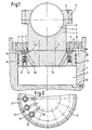
- a plunger 1 is provided, on which a connecting rod attachment 2 is fixed, which carries a ball socket 3, which receives a connecting rod pin ball 4, which is fixed by means of a ball socket cover 5 by screws 6.
- a chamber-like cylinder 7 is formed, which is covered at the top by means of a stop ring 8 which is screwed on.
- the connecting rod attachment 2 penetrates the stop ring 8 like a piston rod and is sealed off from it by means of a seal 9.
- a piston 10 is fastened to the connecting rod attachment 2 by means of screws 6, which piston can be moved up and down in the cylinder 7 and is sealed off from it by means of seals 9. The piston 10 has been moved against the stop ring 8 according to FIG. 1.
- the piston 10 is provided with a chain of outlet valves 11 in the area projecting laterally from the connecting rod attachment along a circular ring, each of which is equipped with a disk-like or plate-like valve body 12 which has a tire-like peripheral surface.
- the valve body 12 is placed in a recess 13 which widens conically from bottom to top and receives the valve body 12 in depth to the extent that it is acted upon by the stop ring on the outside and is pressed down.
- the recess 13 then forms a ring-like valve seat over a step and continues with a constricted cross-section downward.
- a bore 14 is provided coaxially with the recess 13, into which a valve tappet 15 of the valve body projects, on which a compressed spring 16 sits, which is supported on a crosspiece 17 at the end of the valve tappet.
- the spring 16 urges the valve body 12 onto the valve seat.
- a channel 18 extends obliquely from the pot-like extension of the recess 13 to the underside of the piston 10.
- pressure fluid is introduced via an inlet 19, which is supplied by a pump via a first overload or safety valve, a check valve and a second overload or safety valve is supplied.
- the pressure fluid that emerges at the top of the piston 10 is discharged via an outlet 20.
- the drain valves 11 are enclosed on the outside with a self-contained channel 21 on the top of the piston, which is intended to avoid an undesired dwell of fluid on the piston 10.
- fluid flows slowly into the cylinder 7, causing the piston 10 to rise until it reaches the stop ring 8.
- the pressure fluid e.g. is a liquid
- the pressure fluid now builds up a pressure defined by the overload valve and presses the valve body 12 against the stop ring.
- the piston 10 lowers, the valve bodies 12 being raised or remaining and continue to be pressed by the pressure fluid against the stop ring 8.
- the number of outlet valves and their flow cross-section determine the speed at which the fluid travels from the underside of the piston to the top of the piston.
- the cylinder 7 sits as an independent piece in a housing 36 and protrudes therefrom with a sleeve 22 which receives a first shaft 23.
- a plurality of identical overload pistons 10 are arranged in a circle in the cylinder 7 and are guided on the cylinder wall and a central piece 24.
- Each overload piston 10 is equipped with outlet valves 11, as shown in FIGS. 1 and 2.
- the inlet 19 is guided centrally along the first shaft 23 and enters the partial areas of the cylinder assigned to the individual overload pistons via a branch 25.
- the cylinder 7 is closed with the plate-like stop ring 8 and each overload piston 10 projects with an extension 2 through the stop ring, it being sealed in a manner not shown.
- the stop ring 8 has two bores 26 per overload valve 11, which lead to the outlet 20, which is formed between a cover plate 27 and the stop ring 8.
- a spherical shell-shaped depression is formed, in which a spherical segment 28 fits, which sits on a clutch disc 29. All parts are seated in the housing 21 up to the clutch disc 29.
- a sleeve 30 fastened to the clutch disc protrudes from the housing and receives a second shaft 31. It is conceivable to arrange a compression spring between each overload piston 10 and the cylinder base in order to bring the overload piston into operative position and to close the outlet valves.
- the cylinder 7 is filled with pressurized fluid via the inlet 19, the overload pistons 10 are in the operative position and the outlet valves 11 are closed. If the rotational load between the two shafts 23, 31 becomes too great, the overload pistons 10 are shifted somewhat to the left with compression of the pressure cushion, that is to say the fluid in the cylinder in FIG. that the coupling between the two shafts is released.
- the cylinder 7 provided with the inlet 19 is designed independently and is firmly connected via a linkage 32 to a first sliding piece 33, in contrast to which a second sliding piece 34 can be fixed and displaced.
- the piston 10 projects with the neck 2 through the stop ring 8, which limits the outlet 20 with the cover plate 27.
- the piston 10 is equipped with outlet valves 11 and the stop ring 8 has bores 26.
- the approach 2 protrudes with a tapered end piece in an adapted recess of a coupling block 35 which is attached to the second sliding piece 34.
Landscapes
- Engineering & Computer Science (AREA)
- Mechanical Engineering (AREA)
- Safety Valves (AREA)
- Check Valves (AREA)
- Fluid-Damping Devices (AREA)
- Actuator (AREA)
Description
- Die Erfindung betrifft eine Vorrichtung zum raschen Auslaufen einer Druckpolster-Überlastsicherung, bei der ein Kolben vom Druckpolster-Druck in einem Zylinder in Wirkstellung gedrückt ist und bei überlast sich geringfügig aus der Wirkstellung verschiebt und bei dem zwischen Druckpolster und Außenseite ein Auslaufventil vorgesehen ist, dessen Ventilkörper auf einer Seite vom Druckpolster beaufschlagt und bei Wirkstellung des Kolbens auf der dem Druckpolster gegenüberliegenden Seite abgestützt ist, wobei er bei Sperrstellung in den Ventilsitz gedrückt ist.
- Bei einer bekannten (DE-B-2150 726) Vorrichtung dieser Art ist das Ventil an einer vom Druckpolster wegführenden Leitung vorgesehen und ist der Ventilkörper über eine Feder an einem ortsfesten Teil abgestützt. Der Ventilkörper weist eine kegelige Innenfläche auf, von der nur der Spitzenbereich ständig vom Druckpolster beaufschlagt ist. Bei Überlast wird der Ventilkörper etwas zurückgedrückt, so daß die gesamte Innenfläche des Ventilkörpers beaufschlagt ist, was den Ventilkörper schlagartig in Offenstellung bringt. Diese Vorrichtung arbeitet zeitraubend, da zunächst der zur Überlast gehörende Druck aufgebaut werden muß, dann durch Zurückdrücken des spitzen Bereiches ein Sicherheitsventil betätigt wird und dann das eigentliche Ablaufventil betätigt wird.
- Es ist auch eine Vorrichtung mit einer Überlastsicherung bekannt (GB-A-2 031 519), bei der in einem Kolben ein Auslaufventil angeordnet ist. Jedoch ist der Kolben ein Arbeitskolben, der dazu dient, in dem Arbeitszylinder angeordnet, einen Stößel anzutreiben. Dabei ist das Auslaufventil auf der einen Seite vom Druckraum her belastet. Es wird angenommen, daß es sich um ein Ventil handelt, das einerseits von dem über den Zulauf zugeführten Arbeitsdruck und andererseits von einer Feder beaufschlagt ist und das öffnet, wenn die durch den Arbeitsdruck bewirkte Kraft den durch die Feder bewirkte Kraft übersteigt.
- Eine Aufgabe der Erfindung ist es nun, eine Vorrichtung der eingangs genannten Art zu schaffen, die mit einfachen Mitteln schneller arbeitet. Die erfindungsgemäße Vorrichtung ist, diese Aufgabe lösend, dadurch gekennzeichnet, daß das Auslaufventil im Kolben angeordnet ist und daß der Ventilköper des Auslaufventiles bei Sperrstellung mittels des vom Druckpolster- Druck beaufschlagten Kolbens einerseits in den Ventilsitz und andererseits gegen eine Abstützung des Zylinders gedrückt ist, so daß bei Überlast der Ventilsitz vom Ventilkörper abhebt und der Ventilköper an die Abstützung gedrückt ist.
- Das Druckpolster drückt den Ventilkörper des Auslaufventiles ständig gegen die Abstützung und zwar auch bei überlast. Da das Druckpolster den Kolben in Wirkstellung drückt, wird auch der Ventilsitz dichtend gegen den abgestützten Ventilkörper gedrückt. Wenn der Überlast-Druck auftritt, so bewegt sich der Kolben etwas aus der Wirkstellung, wodurch der Ventilsitz vom Ventilkörper abhebt, d. h. das Auslaufventil öffnet, so daß das Druckpolster auslaufen kann. Da die anfängliche Verschiebung des Kolbens mit dem Aufbau des Überlast-Druckes erfolgt und gleichzeitig damit das Öffnen des Auslaufventiles, ist eine erhebliche Verkürzung der Reaktionszeit der Überlastsicherung erreicht. Bei geeigneter Gestaltung des Auslaufventiles ist dessen Auslaufquerschnitt für eine befriedigend rasche Entleerung ausreichend groß.
- Es ist möglich, das Druckpolster mit einem praktisch inkompressiblen Fluidum zu bilden und den Druckpolsterdruck durch ein Sicherheitsventil festzulegen, um die erwünschte anfängliche Verschiebung des Kolbens zu erreichen. In diesem Fall kann der Ventilkörper auf dem Ventilsitz aufliegen und öffnet schon aufgrund einer sehr geringen Änderung des Volumens des Druckpolsters.
- Andererseits ist es auch zweckmäßig und vorteilhaft, wenn das Fluidum des Druckpolsters bei Überlast-Druck merklich kompressibel ist und der Ventilköper bei Sperrstellung und Offenstellung in eine vom Ventilsitz gebildete Buchse eintaucht. Es wird aufgrund einer etwas stärkeren Volumenänderung des Druckpolsters der Buchsenbereich vom Ventilkörper abgezogen, um das Auslaufventil zu öffnen.
- Besonders zweckmäßig und vorteilhaft ist es sodann, wenn der Ventilkörper in einer Ausnehmung des Kolbens angeordnet ist, deren Querschnitt auf der dem Ventilsitz abgewandten Seite merklich größer als der des Ventilkörpers ist. Der Ventilkörper ist geschützt angeordnet und ausreichende Abflußmöglichkeit ist gewährleistet.
- Besonders zweckmäßig und vorteilhaft ist es noch, wenn der Ventilkörper mittels Feder gegen den Kolben gedrückt ist. Der Überlast-Druck überwindet die Kraft dieser Zugfeder und die Zugfeder schließt das Auslaufventil nach Abbau des Überlast-Druckes wieder.
- Besonders zweckmäßig und vorteilhaft ist es weiterhin, wenn der Kolben mit mehreren verteilt angeordneten Auslaufventilen bestückt ist. Ohne das einzelne Auslaufventil allzu groß dimensionieren zu müssen, ist durch die Verteilung mehrerer Auslaufventile über den Kolben, der Abfluß des das Druckpolster bildenden Druckfluidums beschleunigt.
- Die erfindungsgemäße Vorrichtung läßt sich in verschiedenster Weise einsetzen. z. B. kann damit gemäß DE-C-1 627 940 der Zuganker einer Spindelschlagpresse gesichert werden. Es ist aber auch möglich, mit der erfindungsgemäßen Vorrichtung einen Drehmomentwandler zu sichern. Die Auslaufventile können zwischen Ventilkörper und Ventilsitz Dichtringe aufweisen.
- In der Zeichnung sind bevorzugte Ausführungsformen der Erfindung dargestellt und zeigt
- Fig. 1 einen vertikalen Schnitt einer Druckpolster-Überlastsichere an der Pleuelbefestigung einer Presse,
- Fig. 2 eine Draufsicht auf einen Teil der Darstellung gemäß Fig. 1,
- Fig. 3 einen vertikalen Schnitt einer Druckpolster-Überlastsicherung einer Wellenkupplung und
- Fig. 4 einen vertikalen Schnitt einer Druckpolster-Überlastsicherung einer Schubkupplung.
- Gemäß Fig. 1 und 2 ist ein Stößel 1 vorgesehen, an dem ein Pleuelansatz 2 festgelegt ist, der eine Kugelpfanne 3 trägt, die eine Pleuelzapfenkugel 4 aufnimmt, die mittels eines Kugelpfannendeckels 5 durch Schrauben 6 festgelegt ist. In dem Stößel 1 ist ein kammerartiger Zylinder 7 gebildet, der oben mittels eines Anschlagringes 8 abgedeckt ist, der angeschraubt ist. Der Pleuelansatz 2 durchdringt wie eine Kolbenstange den Anschlagring 8 und ist gegenüber diesem mittels Dichtung 9 abgedichtet. Im Zylinder 7 ist am Pleuelansatz 2 mittels Schrauben 6 ein Kolben 10 befestigt, der im Zylinder 7 auf und ab verschiebbar ist und gegenüber diesem mittels Dichtungen 9 abgedichtet ist. Der Kolben 10 ist gemäß Fig. 1 gegen den Anschlagring 8 gefahren.
- Der Kolben 10 ist in dem dem Pleuelansatz seitlich überragenden Bereich entlang einem Kreisring mit einer Kette von Auslaufventilen 11 versehen, die jeweils mit einem scheibenartigen bzw. plattenartigen Ventilkörper 12 ausgerüstet sind, der eine reifenartige Umfangsfläche aufweist. Der Ventilkörper 12 ist in eine Ausnehmung 13 gesetzt, die sich von unten nach oben konisch erweitert und den Ventilkörper 12 der Tiefe nach soweit aufnimmt, daß er vom Anschlagring an der Außenseite beaufschlagt ist und nach unten gedrückt ist. Die Ausnehmung 13 bildet dann über eine Stufe einen ringartigen Ventilsitz und setzt sich mit verengtem Querschnitt topfartig nach unten fort. Von der Unterseite des Kolbens ist koaxial zur Ausnehmung 13 eine Bohrung 14 vorgesehen, in die ein Ventilstößel 15 des Ventilkörpers ragt, auf dem eine komprimierte Feder 16 sitzt, die an einem Querstück 17 am Ende des Ventilstößels abgestützt ist. Die Feder 16 drängt den Ventilkörper 12 auf den Ventilsitz.
- Von dem topfartigen Fortsatz der Ausnehmung 13 geht jeweils ein Kanal 18 schräg zur Unterseite des Kolbens 10. In dem Zylinder 7 unter dem Kolben 10 wird über einen Zulauf 19 Druckfluidum eingeführt, das von einer Pumpe über ein erstes Überlast- oder Sicherheitsventil, ein Rückschlagventil und ein zweites Überlast- oder Sicherheitsventil zugeführt wird.
- Dies ist an sich bekannt und nicht näher gezeigt. Das Druckfluidum, das an der Oberseite des Kolbens 10 austritt, wird über einen Ablauf 20 abgeführt. Die Ablaufventile 11 sind außen mit einer in sich geschlossenen Rinne 21 an der Oberseite des Kolbens umschlossen, die ein unerwünschtes Verweilen von Fluidum auf dem Kolben 10 vermeiden soll.
- Zunächst strömt Fluidum langsam in den Zylinder 7, wodurch sich der Kolben 10 hebt, bis er den Anschlagring 8 erreicht. Das Druckfluidum, das z.B. eine Flüssigkeit ist, baut jetzt einen durch das Überlastventil definierten Druck auf und drückt die Ventilkörper 12 gegen den Anschlagring. Bei einer Überlastung senkt sich der Kolben 10, wobei die Ventilkörper 12 angehoben werden oder bleiben und vom Druckfluidum weiterhin gegen den Anschlagring 8 gedrückt werden. Die Anzahl der Auslaufventile und deren Strömungsquerschnitt bestimmen die Geschwindigkeit, mit der das Fluidum von der Kolbenunterseite auf die Kolbenoberseite wandert. Bei erneuter Einrichtung der Überlastsicherung wird beim Beaufschlagen des Kolbens mit Fluidum das sich oberhalb des Kolbens befindende Fluidum durch den Abfluß 20 gedrängt.
- Bei der Druckpolster-Überlastsicherung gemäß Fig. 3 sitzt der Zylinder 7 als eigenständiges Stück in einem Gehäuse 36 und ragt aus diesem mit einer Muffe 22 heraus, die eine erste Welle 23 aufnimmt. In dem Zylinder 7 sind mehrere gleiche Überlastkolben 10 im Kreis angeordnet, die an der Zylinderwand und einem Mittelstück 24 geführt sind. Jeder Überlastkolben 10 ist mit Auslaufventilen 11 bestückt, wie es in Fig. 1 und 2 gezeigt ist. Der Zulauf 19 ist mittig entlang der ersten Welle 23 geführt und tritt über eine Verzweigung 25 in die den einzelnen Überlastkolben zugeordneten Teilbereiche des Zylinders.
- Der Zylinder 7 ist mit dem plattenartigen Anschlagring 8 abgeschlossen und jeder Überlastkolben 10 ragt mit einem Ansatz 2 durch den Anschlagring, wobei er in nicht gezeigter Weise abgedichtet ist. Der Anschlagring 8 weist pro Überlastventil 11 zwei Bohrungen 26 auf, die zum Auslauf 20 führen, der zwischen einer Deckplatte 27 und dem Anschlagring 8 gebildet ist. An den freien Enden der Ansätze 2 ist jeweils eine kugelschalenförmige Mulde gebildet, in die ein Kugelsegment 28 passend eingreift, das an einer Kupplungsscheibe 29 sitzt. Bis zur Kupplungsscheibe 29 sitzen alle Teile im Gehäuse 21. Eine an der Kupplungsscheibe befestigte Muffe 30 ragt aus dem Gehäuse und nimmt eine zweite Welle 31 auf. Es ist denkbar, zwischen Jedem Überlastkolben 10 und dem Zylinderboden eine Druckfeder anzuordnen, um den Überlastkolben in Wirkstellung zu bringen und die Auslaufventile zu schliessen.
- Zunächst ist der Zylinder 7 über den Zulauf 19 mit Druckfluidum gefüllt, befinden sich die Überlastkolben 10 in Wirkstellung und sind die Auslaufventile 11 geschlossen. Wenn die Drehlast zwischen den beiden Wellen 23, 31 zu groß wird, werden die Überlastkolben 10 unter Kompression des Druckpolsters, d.h. des Fluidums im Zylinder in Fig. 3 etwas nach links verschoben, wodurch die Auslaufventile 11 öffnen und das Druckpolster schlagartig soweit auslaufen kann, daß die Kupplung zwischen den beiden Wellen sich löst.
- Bei der Ausführungsform gemäß Fig. 4 ist der mit dem Zulauf 19 versehene Zylinder 7 selbständig ausgebildet und über ein Gestänge 32 mit einem ersten Schiebestück 33 fest verbunden, demgegenüber ein zweites Schiebestück 34 festlegbar und verschiebbar ist. Der Kolben 10 ragt mit dem Ansatz 2 durch den Anschlagring 8, der mit der Deckplatte 27 den Auslauf 20 begrenzt. Der Kolben 10 ist mit Auslaufventilen 11 bestückt und der Anschlagring 8 weist Bohrungen 26 auf. Der Ansatz 2 ragt mit einem sich verjüngenden Endstück in eine angepaßte Ausnehmung eines Kupplungsblockes 35, der am zweiten Schiebestück 34 befestigt ist. Wenn der Kolben 10 weit genug in dem Zylinder, in Fig. 4 nach links, zurückgefahren ist, ist die Kupplung zwischen Ansatz 2 und Kupplungsblock 35 gelöst.
Claims (7)
Priority Applications (1)
| Application Number | Priority Date | Filing Date | Title |
|---|---|---|---|
| AT86103073T ATE38415T1 (de) | 1985-03-08 | 1986-03-07 | Druckpolster-ueberlastsicherung. |
Applications Claiming Priority (2)
| Application Number | Priority Date | Filing Date | Title |
|---|---|---|---|
| DE3508245 | 1985-03-08 | ||
| DE19853508245 DE3508245A1 (de) | 1985-03-08 | 1985-03-08 | Druckpolster-ueberlastsicherung |
Publications (2)
| Publication Number | Publication Date |
|---|---|
| EP0193971A1 EP0193971A1 (de) | 1986-09-10 |
| EP0193971B1 true EP0193971B1 (de) | 1988-11-02 |
Family
ID=6264580
Family Applications (1)
| Application Number | Title | Priority Date | Filing Date |
|---|---|---|---|
| EP86103073A Expired EP0193971B1 (de) | 1985-03-08 | 1986-03-07 | Druckpolster-Überlastsicherung |
Country Status (3)
| Country | Link |
|---|---|
| EP (1) | EP0193971B1 (de) |
| AT (1) | ATE38415T1 (de) |
| DE (1) | DE3508245A1 (de) |
Families Citing this family (1)
| Publication number | Priority date | Publication date | Assignee | Title |
|---|---|---|---|---|
| DE19532962A1 (de) * | 1995-09-07 | 1997-03-13 | Ulrich Keller | Steuerventil, insbesondere für hydraulische Überlasteinrichtungen bei Pressen |
Family Cites Families (14)
| Publication number | Priority date | Publication date | Assignee | Title |
|---|---|---|---|---|
| FR414012A (fr) * | 1910-03-24 | 1910-08-24 | Schuler Gmbh L | Compensateur hydraulique pour presses |
| DE1046500B (de) * | 1954-07-01 | 1958-12-11 | Eisen & Stahlind Ag | Hydraulische UEberlastungssicherung an Pressen oder aehnlichen Werkzeugmaschinen |
| DE1228512B (de) * | 1961-02-21 | 1966-11-10 | Beteiligungs & Patentverw Gmbh | Hydraulische UEberlastungssicherung |
| DE1904376U (de) * | 1964-09-03 | 1964-11-12 | Auto Union Gmbh | Vorrichtung zum verzoegerten und selbsttaetigen rueckfuehren von betaetigungsgestaengen oder -zuegen. |
| DE1576125A1 (de) * | 1966-02-09 | 1970-01-29 | Langen & Co | Einfach wirkender Hydraulik-Zylinder |
| DE6945901U (de) * | 1969-11-26 | 1970-04-09 | Otto Entwicklungsbuero | Kolbenzylinderanordnung |
| DE2150726C3 (de) * | 1971-10-12 | 1979-10-11 | Novopress Gmbh Pressen Und Presswerkzeuge & Co Kg, 4000 Duesseldorf | Spindelpresse |
| US4258609A (en) * | 1977-10-11 | 1981-03-31 | Conway John P | Dual speed hydraulic piston assembly |
| GB2031519B (en) * | 1978-10-13 | 1982-09-08 | Coal Ind | Hydraulic actuator with relief valve |
| DE2945199A1 (de) * | 1979-11-09 | 1981-05-14 | Manfred 5630 Remscheid Boese | Hydraulikzylinder mit vorgespannter kolbenstange |
| DE3037082A1 (de) * | 1980-10-01 | 1982-05-06 | Malmedie & Co Maschinenfabrik GmbH, 4000 Düsseldorf | Ueberlastsicherung an einer werkzeugmaschine, insbesonder einer drueck- oder streckdrueckmaschine |
| US4375181A (en) * | 1981-01-21 | 1983-03-01 | Conway John P | Hydraulic cylinder extending in three force modes |
| JPS5857335U (ja) * | 1981-10-12 | 1983-04-18 | 株式会社小松製作所 | フイ−ダの駆動装置 |
| DD212695A1 (de) * | 1982-12-22 | 1984-08-22 | Blechbearbeitungsmaschinenwerk | Hydraulische ueberlastsicherung fuer mechanische pressen |
-
1985
- 1985-03-08 DE DE19853508245 patent/DE3508245A1/de active Granted
-
1986
- 1986-03-07 AT AT86103073T patent/ATE38415T1/de not_active IP Right Cessation
- 1986-03-07 EP EP86103073A patent/EP0193971B1/de not_active Expired
Also Published As
| Publication number | Publication date |
|---|---|
| ATE38415T1 (de) | 1988-11-15 |
| DE3508245C2 (de) | 1989-07-06 |
| EP0193971A1 (de) | 1986-09-10 |
| DE3508245A1 (de) | 1986-09-11 |
Similar Documents
| Publication | Publication Date | Title |
|---|---|---|
| DE6930249U (de) | Bremsdruckproportionierer fuer hydraulische bremsanlagen von kraftfahrzeugen. | |
| DE1903042A1 (de) | Physikalische Pruefmaschine | |
| EP1179149B1 (de) | Dichtungsvorrichtung für einen mit druckmittel beaufschlagten kolben in einem arbeitszylinder | |
| DE3430526C1 (de) | Stempelsteuerventil | |
| DE2405799A1 (de) | Tellerventil | |
| DE2109378B2 (de) | Rueckschlagventil mit zusaetzlicher betaetigung | |
| DE2544507C3 (de) | Überlastschutzeinrichtung für Pressen o.dgl | |
| DE69300384T2 (de) | Absperrhahn mit konischen Küken. | |
| DE1555387B2 (de) | Druckminderer fuer hydraulische fahrzeug-bremsanlagen | |
| EP0193971A1 (de) | Druckpolster-Überlastsicherung | |
| DE2021857C3 (de) | Bremsventil | |
| DE2559645C3 (de) | Druckmittelbetätigte Ausrückkupplung | |
| DE1528384C3 (de) | Pumpenkolben-Abstützung | |
| DE2060468A1 (de) | Hochdruckgeraet | |
| DE1014501B (de) | Hydraulischer Grubenstempel mit einem Druckraum und einem UEberdruckventil | |
| DE69408675T2 (de) | Rotator | |
| DE8506729U1 (de) | Druckpolster-Überlastsicherung | |
| DE1013245B (de) | Hydraulischer Grubenstempel | |
| DE2315029A1 (de) | Pressenkopf | |
| DE2949014C2 (de) | Kraftstoffeinspritzpumpe für Brennkraftmaschinen | |
| DE4400677A1 (de) | Entlastungsventil für ein Strebausbaugestell | |
| DE3926847C2 (de) | ||
| DE2062533C3 (de) | Bremskraftverstärker für eine hydraulische Zweikreisbremsanlage für Fahrzeuge | |
| DE3712635A1 (de) | Hydraulischer arbeitszylinder, insbesondere in im bergbau ueblichen stempeln | |
| DE2626371A1 (de) | Druckregulierungsvorrichtung |
Legal Events
| Date | Code | Title | Description |
|---|---|---|---|
| PUAI | Public reference made under article 153(3) epc to a published international application that has entered the european phase |
Free format text: ORIGINAL CODE: 0009012 |
|
| AK | Designated contracting states |
Kind code of ref document: A1 Designated state(s): AT BE CH DE FR GB IT LI LU NL SE |
|
| RBV | Designated contracting states (corrected) |
Designated state(s): AT BE CH FR GB LI LU SE |
|
| 17P | Request for examination filed |
Effective date: 19870227 |
|
| 17Q | First examination report despatched |
Effective date: 19870709 |
|
| GRAA | (expected) grant |
Free format text: ORIGINAL CODE: 0009210 |
|
| AK | Designated contracting states |
Kind code of ref document: B1 Designated state(s): AT BE CH FR GB LI LU SE |
|
| REF | Corresponds to: |
Ref document number: 38415 Country of ref document: AT Date of ref document: 19881115 Kind code of ref document: T |
|
| GBT | Gb: translation of ep patent filed (gb section 77(6)(a)/1977) | ||
| ET | Fr: translation filed | ||
| PGFP | Annual fee paid to national office [announced via postgrant information from national office to epo] |
Ref country code: CH Payment date: 19890223 Year of fee payment: 4 |
|
| PGFP | Annual fee paid to national office [announced via postgrant information from national office to epo] |
Ref country code: LU Payment date: 19890227 Year of fee payment: 4 |
|
| PGFP | Annual fee paid to national office [announced via postgrant information from national office to epo] |
Ref country code: FR Payment date: 19890228 Year of fee payment: 4 |
|
| PGFP | Annual fee paid to national office [announced via postgrant information from national office to epo] |
Ref country code: BE Payment date: 19890308 Year of fee payment: 4 |
|
| PGFP | Annual fee paid to national office [announced via postgrant information from national office to epo] |
Ref country code: SE Payment date: 19890317 Year of fee payment: 4 |
|
| PG25 | Lapsed in a contracting state [announced via postgrant information from national office to epo] |
Ref country code: LU Free format text: LAPSE BECAUSE OF NON-PAYMENT OF DUE FEES Effective date: 19890331 |
|
| PGFP | Annual fee paid to national office [announced via postgrant information from national office to epo] |
Ref country code: AT Payment date: 19890331 Year of fee payment: 4 |
|
| PLBE | No opposition filed within time limit |
Free format text: ORIGINAL CODE: 0009261 |
|
| STAA | Information on the status of an ep patent application or granted ep patent |
Free format text: STATUS: NO OPPOSITION FILED WITHIN TIME LIMIT |
|
| 26N | No opposition filed | ||
| PG25 | Lapsed in a contracting state [announced via postgrant information from national office to epo] |
Ref country code: GB Effective date: 19900307 Ref country code: AT Effective date: 19900307 |
|
| PG25 | Lapsed in a contracting state [announced via postgrant information from national office to epo] |
Ref country code: SE Effective date: 19900308 |
|
| PG25 | Lapsed in a contracting state [announced via postgrant information from national office to epo] |
Ref country code: CH Effective date: 19900331 Ref country code: LI Effective date: 19900331 Ref country code: BE Effective date: 19900331 |
|
| BERE | Be: lapsed |
Owner name: LANGE JORG Effective date: 19900331 |
|
| GBPC | Gb: european patent ceased through non-payment of renewal fee | ||
| REG | Reference to a national code |
Ref country code: CH Ref legal event code: PL |
|
| EUG | Se: european patent has lapsed |
Ref document number: 86103073.2 Effective date: 19910110 |
|
| PG25 | Lapsed in a contracting state [announced via postgrant information from national office to epo] |
Ref country code: FR Effective date: 19950731 |
|
| REG | Reference to a national code |
Ref country code: FR Ref legal event code: ST |
|
| PG25 | Lapsed in a contracting state [announced via postgrant information from national office to epo] |
Ref country code: FR Effective date: 19900331 |