EP0191982B1 - Keramischer Wabenkörper - Google Patents
Keramischer Wabenkörper Download PDFInfo
- Publication number
- EP0191982B1 EP0191982B1 EP85308685A EP85308685A EP0191982B1 EP 0191982 B1 EP0191982 B1 EP 0191982B1 EP 85308685 A EP85308685 A EP 85308685A EP 85308685 A EP85308685 A EP 85308685A EP 0191982 B1 EP0191982 B1 EP 0191982B1
- Authority
- EP
- European Patent Office
- Prior art keywords
- honeycomb body
- ceramic honeycomb
- fins
- partition walls
- holes
- Prior art date
- Legal status (The legal status is an assumption and is not a legal conclusion. Google has not performed a legal analysis and makes no representation as to the accuracy of the status listed.)
- Expired
Links
Images

Classifications
-
- C—CHEMISTRY; METALLURGY
- C04—CEMENTS; CONCRETE; ARTIFICIAL STONE; CERAMICS; REFRACTORIES
- C04B—LIME, MAGNESIA; SLAG; CEMENTS; COMPOSITIONS THEREOF, e.g. MORTARS, CONCRETE OR LIKE BUILDING MATERIALS; ARTIFICIAL STONE; CERAMICS; REFRACTORIES; TREATMENT OF NATURAL STONE
- C04B38/00—Porous mortars, concrete, artificial stone or ceramic ware; Preparation thereof
- C04B38/0006—Honeycomb structures
-
- B—PERFORMING OPERATIONS; TRANSPORTING
- B01—PHYSICAL OR CHEMICAL PROCESSES OR APPARATUS IN GENERAL
- B01D—SEPARATION
- B01D46/00—Filters or filtering processes specially modified for separating dispersed particles from gases or vapours
- B01D46/10—Particle separators, e.g. dust precipitators, using filter plates, sheets or pads having plane surfaces
-
- F—MECHANICAL ENGINEERING; LIGHTING; HEATING; WEAPONS; BLASTING
- F01—MACHINES OR ENGINES IN GENERAL; ENGINE PLANTS IN GENERAL; STEAM ENGINES
- F01N—GAS-FLOW SILENCERS OR EXHAUST APPARATUS FOR MACHINES OR ENGINES IN GENERAL; GAS-FLOW SILENCERS OR EXHAUST APPARATUS FOR INTERNAL-COMBUSTION ENGINES
- F01N3/00—Exhaust or silencing apparatus having means for purifying, rendering innocuous, or otherwise treating exhaust
- F01N3/08—Exhaust or silencing apparatus having means for purifying, rendering innocuous, or otherwise treating exhaust for rendering innocuous
- F01N3/10—Exhaust or silencing apparatus having means for purifying, rendering innocuous, or otherwise treating exhaust for rendering innocuous by thermal or catalytic conversion of noxious components of exhaust
- F01N3/24—Exhaust or silencing apparatus having means for purifying, rendering innocuous, or otherwise treating exhaust for rendering innocuous by thermal or catalytic conversion of noxious components of exhaust characterised by constructional aspects of converting apparatus
- F01N3/28—Construction of catalytic reactors
- F01N3/2803—Construction of catalytic reactors characterised by structure, by material or by manufacturing of catalyst support
- F01N3/2825—Ceramics
- F01N3/2828—Ceramic multi-channel monoliths, e.g. honeycombs
-
- B—PERFORMING OPERATIONS; TRANSPORTING
- B01—PHYSICAL OR CHEMICAL PROCESSES OR APPARATUS IN GENERAL
- B01J—CHEMICAL OR PHYSICAL PROCESSES, e.g. CATALYSIS OR COLLOID CHEMISTRY; THEIR RELEVANT APPARATUS
- B01J35/00—Catalysts, in general, characterised by their form or physical properties
- B01J35/50—Catalysts, in general, characterised by their form or physical properties characterised by their shape or configuration
- B01J35/56—Foraminous structures having flow-through passages or channels, e.g. grids or three-dimensional monoliths
-
- F—MECHANICAL ENGINEERING; LIGHTING; HEATING; WEAPONS; BLASTING
- F01—MACHINES OR ENGINES IN GENERAL; ENGINE PLANTS IN GENERAL; STEAM ENGINES
- F01N—GAS-FLOW SILENCERS OR EXHAUST APPARATUS FOR MACHINES OR ENGINES IN GENERAL; GAS-FLOW SILENCERS OR EXHAUST APPARATUS FOR INTERNAL-COMBUSTION ENGINES
- F01N2330/00—Structure of catalyst support or particle filter
- F01N2330/06—Ceramic, e.g. monoliths
-
- F—MECHANICAL ENGINEERING; LIGHTING; HEATING; WEAPONS; BLASTING
- F01—MACHINES OR ENGINES IN GENERAL; ENGINE PLANTS IN GENERAL; STEAM ENGINES
- F01N—GAS-FLOW SILENCERS OR EXHAUST APPARATUS FOR MACHINES OR ENGINES IN GENERAL; GAS-FLOW SILENCERS OR EXHAUST APPARATUS FOR INTERNAL-COMBUSTION ENGINES
- F01N2330/00—Structure of catalyst support or particle filter
- F01N2330/30—Honeycomb supports characterised by their structural details
- F01N2330/38—Honeycomb supports characterised by their structural details flow channels with means to enhance flow mixing,(e.g. protrusions or projections)
-
- Y—GENERAL TAGGING OF NEW TECHNOLOGICAL DEVELOPMENTS; GENERAL TAGGING OF CROSS-SECTIONAL TECHNOLOGIES SPANNING OVER SEVERAL SECTIONS OF THE IPC; TECHNICAL SUBJECTS COVERED BY FORMER USPC CROSS-REFERENCE ART COLLECTIONS [XRACs] AND DIGESTS
- Y10—TECHNICAL SUBJECTS COVERED BY FORMER USPC
- Y10T—TECHNICAL SUBJECTS COVERED BY FORMER US CLASSIFICATION
- Y10T428/00—Stock material or miscellaneous articles
- Y10T428/24—Structurally defined web or sheet [e.g., overall dimension, etc.]
- Y10T428/24149—Honeycomb-like
-
- Y—GENERAL TAGGING OF NEW TECHNOLOGICAL DEVELOPMENTS; GENERAL TAGGING OF CROSS-SECTIONAL TECHNOLOGIES SPANNING OVER SEVERAL SECTIONS OF THE IPC; TECHNICAL SUBJECTS COVERED BY FORMER USPC CROSS-REFERENCE ART COLLECTIONS [XRACs] AND DIGESTS
- Y10—TECHNICAL SUBJECTS COVERED BY FORMER USPC
- Y10T—TECHNICAL SUBJECTS COVERED BY FORMER US CLASSIFICATION
- Y10T428/00—Stock material or miscellaneous articles
- Y10T428/24—Structurally defined web or sheet [e.g., overall dimension, etc.]
- Y10T428/24744—Longitudinal or transverse tubular cavity or cell
Definitions
- This invention relates to a ceramic honeycomb body. More particularly, the invention relates to a ceramic honeycomb body suitable for carrying catalyzers to purify exhaust gas from internal combustion engines, for purifying such exhaust gas by filtering fine particles therefrom, and for purifying and deodorizing combustion gas generated when fuels such as gaseous fuels and petroleum are burnt.
- the ceramic honeycomb body has a high heat resistivity, a high corrosion resistivity, and a low pressure loss for fluid passing therethrough. Besides, their contact area with gas being treated can be made large. Accordingly, it is used in many applications, such as
- the ceramic honeycomb body for the above applications has a number of through holes which provide contact surfaces with the gas treated (in the case of filter, one side end opening of each through hole is closed).
- the cross-sectional shape of the through hole is made triangular, rectangular, circular, or the like, depending on the required levels of pressure loss of combustion gas and thermal shock resistivity.
- combustion gas from a combustion chamber is brought to the ceramic honeycomb body through a pipe, and the total area of end openings of the through holes in the ceramic honeycomb body is made largerthan the cross-sectional area of that pipe so as to provide the required contact area between the gas being treated and the surface of the ceramic honeycomb body. Due to such large total area of the through hole end openings, the conventional ceramic honeycomb body has a shortcoming in that the gas being treated tends to be concentrated at the central portion thereof, so that the central portion of the ceramic honeycomb body tends to be deteriorated quickly and sufficient purifying power cannot be maintained for a long period of time.
- the ceramic honeycomb body of the above-mentioned Japanese Patent Laying-open Publication No. 14 921/1983 which carries ceramic particles attached to the surface of the partition wall thereof, has shortcomings in that the ceramic particles tend to scale off when exposed to thermal shock or mechanical vibration transmitted from the ambient and in that its process of manufacture is complicated.
- the ceramic honeycomb body disclosed by the above-mentioned U.S. Patent No. 3 853 485 has a short-coming in that its thermal shock resistivity is low because its cell density is high at the central portion thereof.
- US-A-3 983 283 shows a honeycomb structure having cell walls in which there are discontinuities so that some cells open into others and in effect constitute larger cells with projecting wall parts extruding thereinto.
- a ceramic honeycomb body having a plurality of through holes each of which holes is bounded by partition walls and a plurality of fins integrally secured to selected partition walls so as to extend into the through holes bounded by such selected partition walls, characterised in that the cross-sectional area of individual through holes, after subtracting the cross-sectional areas of the fins therein, is smaller for through holes in a central portion of the honeycomb body than in other portions, outside the central portion.
- an improved ceramic honeycomb body whose geometrical surface area is enlarged without reducing the thermal shock resistivity thereof.
- Such a ceramic honeycomb body can be produced through a simple process.
- At least the central portion of the ceramic honeycomb body has fins integrally secured to the partition walls thereat.
- the fins and the partition walls in the ceramic honeycomb body of the invention are formed by extrusion and then sintered.
- An example of the material of the partition walls and the fins in the ceramic honeycomb body of the invention is cordierite.
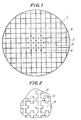
- 1 is a ceramic honeycomb body
- 2 is a partition wall
- 3 is a fin
- 4 is a through hole.
- a ceramic honeycomb body 1 according to the invention has a plurality of through holes 4, each of which is surrounded by partition walls 2. Fins 3 are integrally secured to the surfaces of selected partition walls 2.
- fins 3 are integrally formed on the surfaces of the partition walls 2 only in the central portion of the ceramic honeycomb body 1.
- the reason for providing the fins 3 only in the central portion of the ceramic honeycomb body 1 is in that the gas being treated tends to be concentrated at the central portion of the ceramic honeycomb body 1 in the main, resulting in an accelerated deterioration of the body 1 at the central portion.
- the invention intends to eliminate the occurrence of the accelerated deterioration of the body central portion which tends to hamper efficient purification of the combustion gas.
- the present invention is not restricted to the arrangement of Fig. 1, and the fins 3 can be secured to all the partition walls 2 of the ceramic honeycomb body including those in the peripheral portion thereof.
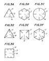
- the height of the fin 3 extending into the through hole 4 is preferably about 20-30% of the length of one side of the partition wall 2 in the case of polygonal through hole 4.
- the thickness of the fin 3 is the same as that of the partition wall 2 in the case of the example of Fig. 1, and preferably the fin 3 is not thicker than the partition wall 2.
- an outer peripheral wall thicker than the partition wall 2 can be provided on the peripheral surface of the ceramic honeycomb body 1.
- the cross-sectional area of the through hole 4 surrounded by such partition walls 2, e.g., the hole 4 in the body central portion, is reduced by an amount corresponding to the total cross-sectional area of the fins 3 in that through hole 4. Accordingly, the thickness of the fin 3 and the thickness of the partition wall 2 should be carefully selected while considering how the ceramic honeycomb body 1 is used.
- the fin 3 is formed as an integral part of the partition wall 2 by extrusion and then sintered.
- the material of the partition wall 2 and the fin 3 is preferably cordierite.
- the material of the ceramic honeycomb body 1 is not restricted only to cordierite as will be described hereinafter.
- the cross-sectional shape of the through hole 4 is not limited to square as shown in Fig. 1.
- the shape ofthe through hole 4defined by the partition wall 2 can be triangular, hexagonal, other polygonal or circular.
- the fin 3 can be secured to the planar portion of the partition wall 2 or at intersections of adjacent partition walls 2, and such position of the fin 3 relative to the partition wall 2 is determined by considering the number of fins 3 to be provided in each through hole 4.
- the total surface area of the ceramic honeycomb body 1 depends on the number and the axial lengths of the through holes 4 and the circumferential lengths of the individual throug holes 4 at their open ends.
- the circumferential length of the through hole 4 depends on both the shape of the through hole 4 defined by the surrounding partition walls 2 and the shape of the fins 3 therein.
- the axial length of the through hole 4 is determined based on the use and the production method of the ceramic honeycomb body 1. Accordingly, the relation between the partition wall 2 and the fin 3 is important.
- One of the objects of the present invention is to increase the surface area of the ceramic honeycomb body 1 by providing fins 3 on the partition wall 2. If the height of the fin 3 (in terms of the length of the fin 3 extending into the through hole 4 as measured from the surface of the partition wall 2) is too high, although the surface area is increased, the pressure loss of the gas being treated becomes too large. Accordingly, the height of the fin 3 is preferably less than 30% of the diameter of an inscribed circle of the through hole 4.
- the preferable thickness of the fin 3 is the same as or less than the thickness of the partition wall 2 from the standpoint of thermal shock resistivity and ease of production.
- the fins 3 are preferably secured to the planar surface of the partition wall 2 but not at intersections thereof, so as to keep the pressure loss low and to ensure effective action of the catalyzers.
- partition walls 2 for the circular through holes 4 as shown in the view (C) of Fig. 3 the geometrical surface area becomes smaller than that in the case of polygonal and utility of the catalyzers is reduced, and the weight increases. Accordingly, partition walls 4 defining rectangular through holes 4 as shown in the views (E) and (G) of Fig. 3 are preferable.
- the provision of the fins 3 is not limited to the central portion of the ceramic honeycomb body 1 as shown in Fig. 1.
- the provision of fins is selected based on the performance requirement for the catalyzers and the required magnitude of the geometrical surface area.
- the fins 3 may be provided not only in the central portion but also in the surroundings thereof. In this case their height can be reduced with increasing distance from the center of the ceramic honeycomb body 1 as shown in Fig. 4.
- the ceramic honeycomb body 1 is most frequently used in a straight passage of combustion gas as a combustion gas purifier because the structure of the ceramic honeycomb body 1 can be very simple in this case.
- the central portion of the ceramic honeycomb body 1 comes in contact with more combustion gas than any other portion thereof does, so that the fins 3 are preferably disposed in the through holes 4 at the central portion of the ceramic honeycomb body 1.
- the through holes 4 with the fins 3 may be disposed at those portions where the flow rate of the combustion gas is the highest.
- the location of the fins 3 is not limited to the exact geometric central portion of the ceramic honeycomb body 1 in the present invention.
- the formation by extrusion is suitable for producing ceramic honeycomb body having long through holes as compared with the cross section thereof, such as the ceramic honeycomb body for purifying exhaust gas from internal combustion engines.
- an inclined portion may be provided between honeycomb shaped grooves and a hole for feeding the material to be extruded so as to facilitate molding of the material into the honeycomb shape, as disclosed in Japanese Patent Publication No. 41 908/1980 (U.S. Patent No. 3 790 654) and Japanese Patent Publication No. 61 592/1982 (U.S. Patent No. 3 905 743).
- a molding slip was prepared by kneading materials for cordierite crystals consisting of 25% of kaolin, 22% of calcined kaolin, 38% of talc, and 15% of alumina, while adding 3.5% of an organic auxiliary for extrusion molding and 30% of water.
- the molding slip was extruded by using dies which were disclosed by the above-mentioned Japanese Patent Publication No. 61 592/1982.
- the extruded body was baked at 1400°C.
- Specimen A (see Table 1); Ceramic honeycomb body having through holes with fins, in the central portion with a diameter 50 mm, fins of heights 0.3 mm and width 0.2 mm being secured to the partition walls.
- Specimen B (see Table 1); Ceramic honeycomb body without any fins, outside diameter 100 mm, height 127 mm, cell pitch 1.47 mm, rib thickness namely partition walls thickness 0.2 mm, cell density 46.5 CM 2 (300/in 2 ), and partition walls defining rectangular through holes.
- Specimen C (see Table 1); Ceramic honeycomb body without any fins, in the central portion with a diameter 50 mm, internal diameter in terms of cell pitch 0.74 mm and cell density 186 cm 2 (1200/in 2 ).
- Specimen A of the ceramic honeycomb body according to the invention proved that the geometrical surface area of the central portion thereof was made large without causing any reduction in the thermal shock resistivity and without any material increase of the pressure loss.
- a ceramic honeycomb body according to the invention has fins integrally secured to the partition walls, so that it provides a large surface area for purifying gas being treated such as combustion gas so as to maximize the purifying efficiency.
Landscapes
- Chemical & Material Sciences (AREA)
- Engineering & Computer Science (AREA)
- Chemical Kinetics & Catalysis (AREA)
- Ceramic Engineering (AREA)
- Toxicology (AREA)
- Structural Engineering (AREA)
- Organic Chemistry (AREA)
- Health & Medical Sciences (AREA)
- Materials Engineering (AREA)
- Combustion & Propulsion (AREA)
- Mechanical Engineering (AREA)
- General Engineering & Computer Science (AREA)
- Catalysts (AREA)
- Exhaust Gas After Treatment (AREA)
- Exhaust Gas Treatment By Means Of Catalyst (AREA)
- Laminated Bodies (AREA)
Claims (4)
Applications Claiming Priority (2)
| Application Number | Priority Date | Filing Date | Title |
|---|---|---|---|
| JP60007362A JPH084749B2 (ja) | 1985-01-21 | 1985-01-21 | セラミツクハニカム構造体 |
| JP7362/85 | 1985-01-21 |
Publications (2)
| Publication Number | Publication Date |
|---|---|
| EP0191982A1 EP0191982A1 (de) | 1986-08-27 |
| EP0191982B1 true EP0191982B1 (de) | 1988-08-24 |
Family
ID=11663850
Family Applications (1)
| Application Number | Title | Priority Date | Filing Date |
|---|---|---|---|
| EP85308685A Expired EP0191982B1 (de) | 1985-01-21 | 1985-11-28 | Keramischer Wabenkörper |
Country Status (5)
| Country | Link |
|---|---|
| US (1) | US4740408A (de) |
| EP (1) | EP0191982B1 (de) |
| JP (1) | JPH084749B2 (de) |
| CA (1) | CA1253130A (de) |
| DE (1) | DE3564560D1 (de) |
Cited By (1)
| Publication number | Priority date | Publication date | Assignee | Title |
|---|---|---|---|---|
| CN102949931A (zh) * | 2012-11-09 | 2013-03-06 | 浙江达峰汽车技术有限公司 | 一种尾气净化用催化净化器的蜂窝载体 |
Families Citing this family (66)
| Publication number | Priority date | Publication date | Assignee | Title |
|---|---|---|---|---|
| US4877670A (en) * | 1985-12-27 | 1989-10-31 | Ngk Insulators, Ltd. | Cordierite honeycomb structural body and method of producing the same |
| JPS62297109A (ja) * | 1986-06-17 | 1987-12-24 | 日本碍子株式会社 | セラミツクハニカム構造体押出成形用ダイス |
| JP2553341B2 (ja) * | 1987-02-26 | 1996-11-13 | 株式会社ユニシアジェックス | 圧力制御弁 |
| JPH0634923B2 (ja) * | 1987-03-14 | 1994-05-11 | 日本碍子株式会社 | セラミツクハニカム構造体 |
| JPS63152638U (de) * | 1987-03-28 | 1988-10-06 | ||
| US4902216A (en) * | 1987-09-08 | 1990-02-20 | Corning Incorporated | Extrusion die for protrusion and/or high cell density ceramic honeycomb structures |
| US4814081A (en) * | 1988-01-19 | 1989-03-21 | Malinowski Raymond J | Honeycombed filter support disc |
| DE3912915C1 (de) * | 1989-04-20 | 1990-12-13 | Degussa Ag, 6000 Frankfurt, De | |
| JP3147372B2 (ja) * | 1990-10-10 | 2001-03-19 | 株式会社日本自動車部品総合研究所 | 排気ガス微粒子捕集用フィルタ |
| GB2250215A (en) * | 1990-11-29 | 1992-06-03 | Rover Group | A catalytic converter |
| US5254840A (en) * | 1991-12-12 | 1993-10-19 | Corning Incorporated | Mounting for metal honeycomb structures |
| US5403184A (en) * | 1992-05-20 | 1995-04-04 | Matsushita Electric Industrial Co., Ltd. | Exothermic apparatus |
| JP3058995B2 (ja) * | 1992-08-18 | 2000-07-04 | 日本碍子株式会社 | ハニカムヒーター |
| NL9201923A (nl) * | 1992-11-04 | 1994-06-01 | Univ Delft Tech | Katalysator-orgaan, reactor voorzien van een dergelijk katalysator-orgaan, mal voor het vervaardigen van een dergelijk katalysator-orgaan, en werkwijze voor het hydrogenerend omzetten van een olie. |
| CA2119604C (en) * | 1993-07-29 | 1997-02-18 | Minoru Machida | Ceramic honeycomb structural body and catalyst comprising the same |
| US5516571A (en) * | 1993-09-01 | 1996-05-14 | Nippon Furnace Kogyo Kaisha, Ltd. | Honeycomb-like regenerative bed element |
| US6045628A (en) * | 1996-04-30 | 2000-04-04 | American Scientific Materials Technologies, L.P. | Thin-walled monolithic metal oxide structures made from metals, and methods for manufacturing such structures |
| US5814164A (en) | 1994-11-09 | 1998-09-29 | American Scientific Materials Technologies L.P. | Thin-walled, monolithic iron oxide structures made from steels, and methods for manufacturing such structures |
| US5736221A (en) * | 1995-07-21 | 1998-04-07 | Hardigg Industries, Inc. | Welded plastic panels and method of making same |
| US5851326A (en) * | 1995-10-25 | 1998-12-22 | Hexcel Corpation | Method for making ceramic honeycomb |
| JP4220584B2 (ja) * | 1997-06-06 | 2009-02-04 | 三菱重工業株式会社 | ハニカム型触媒の製造方法 |
| DE19830342C1 (de) * | 1998-07-07 | 1999-11-25 | Siemens Ag | Katalysatorkörper |
| US6461562B1 (en) | 1999-02-17 | 2002-10-08 | American Scientific Materials Technologies, Lp | Methods of making sintered metal oxide articles |
| JP4094771B2 (ja) * | 1999-06-08 | 2008-06-04 | 日本碍子株式会社 | セラミックフィルタ用基材とその製造方法 |
| US6343923B1 (en) * | 1999-12-02 | 2002-02-05 | Corning Incorporated | Cellular extrusion die |
| NZ523660A (en) * | 2000-07-25 | 2004-07-30 | Shell Int Research | A reactor comprising a packed bed of supported catalyst or supported catalyst precursor, and a use of the reactor |
| JP2004515338A (ja) * | 2000-11-06 | 2004-05-27 | コーニング インコーポレイテッド | 排ガスを浄化するための触媒 |
| JP4186530B2 (ja) * | 2001-08-28 | 2008-11-26 | 株式会社デンソー | 排ガス浄化フィルタの製造方法 |
| JP2003285309A (ja) * | 2002-03-28 | 2003-10-07 | Ngk Insulators Ltd | ハニカム成形用口金 |
| US7410929B2 (en) * | 2002-03-28 | 2008-08-12 | Ngk Insulators, Ltd. | Cell structural body, method of manufacturing cell structural body, and catalyst structural body |
| JP4097971B2 (ja) * | 2002-03-28 | 2008-06-11 | 日本碍子株式会社 | セラミックハニカム構造体の製造方法及びセラミックハニカム構造体 |
| JP3719232B2 (ja) * | 2002-06-18 | 2005-11-24 | トヨタ自動車株式会社 | 内燃機関のパティキュレートフィルタ |
| JP4773043B2 (ja) * | 2003-03-28 | 2011-09-14 | 日本碍子株式会社 | セラミックフィルタ構造体 |
| US20050040260A1 (en) * | 2003-08-21 | 2005-02-24 | Zhibo Zhao | Coaxial low pressure injection method and a gas collimator for a kinetic spray nozzle |
| FR2874647B1 (fr) * | 2004-08-25 | 2009-04-10 | Saint Gobain Ct Recherches | Bloc filtrant a ailettes pour la filtration de particules contenues dans les gaz d'echappement d'un moteur a combustion interne |
| US7384442B2 (en) * | 2005-02-28 | 2008-06-10 | Corning Incorporated | Ceramic wall-flow filter including heat absorbing elements and methods of manufacturing same |
| DE102005055074A1 (de) * | 2005-11-18 | 2007-05-24 | Robert Bosch Gmbh | Filtereinrichtung, insbesondere für ein Abgassystem einer Brennkraftmaschine |
| DE202006007876U1 (de) * | 2006-05-15 | 2007-09-20 | Bauer Technologies Gmbh | Optimierung von zellulären Strukturen, insbesondere für die Abgasreinigung von Verbrennungsaggregaten und andere Anwendungsbereiche |
| CN101687135B (zh) * | 2007-07-05 | 2013-08-14 | 开利公司 | 具有非层流结构的流体净化器 |
| JP4959650B2 (ja) * | 2008-08-07 | 2012-06-27 | 三菱重工業株式会社 | 排ガス処理装置及び排ガス処理システム |
| FR2947735B1 (fr) * | 2009-07-09 | 2011-08-12 | Saint Gobain Ct Recherches | Structure en nid d'abeille marquee |
| CN101816954B (zh) * | 2010-05-13 | 2012-05-30 | 福州大学 | 一种具有改善气液传质作用的结构化光催化剂 |
| EP2926881B1 (de) * | 2012-12-03 | 2018-01-24 | Toyota Jidosha Kabushiki Kaisha | Abgasreinigungsfilter |
| KR20160128343A (ko) * | 2014-03-03 | 2016-11-07 | 스미또모 가가꾸 가부시끼가이샤 | 허니컴 필터 및 허니컴 필터의 제조 방법 |
| DOU2014000190U (es) * | 2014-08-18 | 2016-08-31 | Inst Tecnológico De Santo Domingo Intec | Catalizador de calentamiento automatico en motores de combustion interna |
| JP6451275B2 (ja) * | 2014-12-10 | 2019-01-16 | 株式会社デンソー | ハニカム構造体 |
| JP6409544B2 (ja) * | 2014-12-10 | 2018-10-24 | 株式会社デンソー | ハニカム構造体 |
| CH711115A2 (de) * | 2015-05-22 | 2016-11-30 | Exentis Tech Ag | Mehrstufiger Körper mit einer Vielzahl von Strömungskanälen. |
| US10883400B2 (en) * | 2016-01-21 | 2021-01-05 | Denso Corporation | Honeycomb structure and catalyst body |
| USD837356S1 (en) | 2016-09-15 | 2019-01-01 | Ngk Insulators, Ltd. | Catalyst carrier for exhaust gas purification |
| USD835769S1 (en) * | 2016-09-15 | 2018-12-11 | Ngk Insulators, Ltd. | Catalyst carrier for exhaust gas purification |
| USD837357S1 (en) * | 2016-09-15 | 2019-01-01 | Ngk Insulators, Ltd. | Catalyst carrier for exhaust gas purification |
| JP6824780B2 (ja) * | 2017-03-01 | 2021-02-03 | 日本碍子株式会社 | ハニカムフィルタ |
| CN107023743B (zh) * | 2017-03-08 | 2019-08-20 | 南昌航空大学 | 一种具有可拆卸的圆形降噪结构的正六边形蜂窝芯 |
| JP6767914B2 (ja) * | 2017-03-30 | 2020-10-14 | 日本碍子株式会社 | ハニカム構造体 |
| JP2018167211A (ja) * | 2017-03-30 | 2018-11-01 | 日本碍子株式会社 | ハニカム構造体 |
| JP6775458B2 (ja) * | 2017-03-30 | 2020-10-28 | 日本碍子株式会社 | ハニカム構造体 |
| JP6792500B2 (ja) * | 2017-03-30 | 2020-11-25 | 日本碍子株式会社 | ハニカム構造体 |
| JP6809962B2 (ja) * | 2017-03-30 | 2021-01-06 | 日本碍子株式会社 | ハニカム構造体 |
| JP2018167209A (ja) * | 2017-03-30 | 2018-11-01 | 日本碍子株式会社 | ハニカム構造体 |
| JP6809963B2 (ja) * | 2017-03-30 | 2021-01-06 | 日本碍子株式会社 | ハニカム構造体 |
| JP6782659B2 (ja) * | 2017-03-30 | 2020-11-11 | 日本碍子株式会社 | ハニカム構造体 |
| WO2019070663A1 (en) * | 2017-10-02 | 2019-04-11 | Corning Incorporated | CERAMIC HONEYCOMB BODY AND METHODS OF CANNING |
| US20190247788A1 (en) * | 2018-02-12 | 2019-08-15 | Dürr Systems Inc. | Block apparatus for use with oxidizers |
| USD919072S1 (en) | 2018-02-20 | 2021-05-11 | Ngk Insulators, Ltd. | Catalyst carrier for exhaust gas purification |
| USD1004622S1 (en) | 2018-02-20 | 2023-11-14 | Ngk Insulators, Ltd. | Catalyst carrier for exhaust gas purification |
Family Cites Families (21)
| Publication number | Priority date | Publication date | Assignee | Title |
|---|---|---|---|---|
| US3705617A (en) * | 1970-11-05 | 1972-12-12 | Badger Co | Sublimation apparatus and method |
| US3790654A (en) * | 1971-11-09 | 1974-02-05 | Corning Glass Works | Extrusion method for forming thinwalled honeycomb structures |
| US3905743A (en) * | 1971-11-09 | 1975-09-16 | Corning Glass Works | Extrusion apparatus for forming thin-walled honeycomb structures |
| US3853485A (en) * | 1972-12-11 | 1974-12-10 | Corning Glass Works | Core member for catalytic oxidation converter |
| US3899326A (en) * | 1973-03-30 | 1975-08-12 | Corning Glass Works | Method of making monolithic honeycombed structures |
| US3903341A (en) * | 1973-09-20 | 1975-09-02 | Universal Oil Prod Co | Ceramic honeycomb structure for accommodating compression and tension forces |
| US3885977A (en) * | 1973-11-05 | 1975-05-27 | Corning Glass Works | Anisotropic cordierite monolith |
| US3983283A (en) * | 1974-03-18 | 1976-09-28 | Corning Glass Works | Honeycombed structures having open-ended cells formed by interconnected walls with longitudinally extending discontinuities |
| JPS50127886A (de) * | 1974-03-28 | 1975-10-08 | ||
| US3982100A (en) * | 1974-10-08 | 1976-09-21 | Universal Oil Products Company | Monolithic honeycomb form electric heating device |
| JPS54150406A (en) * | 1978-05-18 | 1979-11-26 | Nippon Soken | Ceramic honeycomb structure |
| EP0025308B1 (de) * | 1979-09-06 | 1984-07-11 | Imperial Chemical Industries Plc | Verfahren und Vorrichtung für den katalytischen Umsatz von Wasserdampf mit Kohlenwasserstoffen unter endothermen Bedingungen |
| CA1145270A (en) * | 1979-12-03 | 1983-04-26 | Morris Berg | Ceramic filters for diesel exhaust particulates and methods of making |
| US4350613A (en) * | 1980-03-11 | 1982-09-21 | Matsushita Electric Industrial Company, Limited | Catalyst for purifying exhaust gases and method for manufacturing same |
| JPS577217A (en) * | 1980-06-16 | 1982-01-14 | Ngk Insulators Ltd | Ceramic honeycomb filter and preparation thereof |
| JPS5726220A (en) * | 1980-07-24 | 1982-02-12 | Ngk Insulators Ltd | Thermal shock resisting ceramic honeycomb-type catalyzer converter |
| US4404007A (en) * | 1980-12-11 | 1983-09-13 | Nippon Soken, Inc. | Exhaust gas cleaning element |
| US4425305A (en) * | 1981-06-01 | 1984-01-10 | Retallick William B | Catalytic creosote burner for a wood stove |
| DD211284A1 (de) * | 1982-08-04 | 1984-07-11 | Gert Grabbert | Packung zur kontaktierung fluider phasen |
| JPS6078707A (ja) * | 1983-10-07 | 1985-05-04 | 日本碍子株式会社 | セラミツクハニカム構造体およびその製法ならびにこれを利用した回転蓄熱式セラミツク熱交換体およびその押出し成形金型 |
| JPS61424A (ja) * | 1984-06-12 | 1986-01-06 | Nippon Denso Co Ltd | セラミツクフイルタ |
-
1985
- 1985-01-21 JP JP60007362A patent/JPH084749B2/ja not_active Expired - Lifetime
- 1985-11-28 EP EP85308685A patent/EP0191982B1/de not_active Expired
- 1985-11-28 DE DE8585308685T patent/DE3564560D1/de not_active Expired
- 1985-11-29 CA CA000496505A patent/CA1253130A/en not_active Expired
- 1985-12-02 US US06/803,237 patent/US4740408A/en not_active Expired - Lifetime
Cited By (1)
| Publication number | Priority date | Publication date | Assignee | Title |
|---|---|---|---|---|
| CN102949931A (zh) * | 2012-11-09 | 2013-03-06 | 浙江达峰汽车技术有限公司 | 一种尾气净化用催化净化器的蜂窝载体 |
Also Published As
| Publication number | Publication date |
|---|---|
| US4740408A (en) | 1988-04-26 |
| DE3564560D1 (en) | 1988-09-29 |
| JPS61167798A (ja) | 1986-07-29 |
| EP0191982A1 (de) | 1986-08-27 |
| JPH084749B2 (ja) | 1996-01-24 |
| CA1253130A (en) | 1989-04-25 |
Similar Documents
| Publication | Publication Date | Title |
|---|---|---|
| EP0191982B1 (de) | Keramischer Wabenkörper | |
| US4464185A (en) | Exhaust gas filter | |
| EP1251247B1 (de) | Filter zum Reinigen von Abgas | |
| US7294316B2 (en) | Honeycomb structure, honeycomb filter and processes for the production thereof | |
| EP1125704B1 (de) | Honigwabenstruktur mit gewellter wandung und verfahren zu deren herstellung | |
| EP1413345B1 (de) | Wabenstrukturkörper und verfahren zur herstellung des sturkturkörpers | |
| CN107199053B (zh) | 蜂窝结构体 | |
| KR20040101345A (ko) | 허니콤 필터 | |
| US8497009B2 (en) | Honeycomb structure and method for manufacturing the same | |
| EP2905058A1 (de) | Wabenstrukturfilter | |
| EP1555254A4 (de) | Verfahren zur herstellung von poröser wabenstruktur und wabenkörper | |
| JP4373177B2 (ja) | ハニカム構造体、その製造方法及びキャニング構造体 | |
| JP2003001029A (ja) | 多孔質セラミックハニカムフィルタ | |
| JPS62266298A (ja) | セラミツクハニカム構造体 | |
| JPH1059784A (ja) | セラミックス製ハニカム構造体 | |
| CN108686509A (zh) | 蜂窝结构体 | |
| JP2005144250A (ja) | ハニカム構造体 | |
| CN110500163B (zh) | 蜂窝结构体 | |
| JP7181704B2 (ja) | ハニカム構造体 | |
| JPH0813337B2 (ja) | セラミックハニカム構造体およびその製造方法 | |
| CN108686506A (zh) | 蜂窝结构体 | |
| JP4155772B2 (ja) | スリット付きハニカム構造体、ハニカム構造体、及びハニカム構造体の製造方法 | |
| JPWO2009041611A1 (ja) | ハニカム構造体およびこれを用いた浄化装置 | |
| JP2012232240A (ja) | ハニカム構造体およびこれを備えるガス処理装置 | |
| JP2018167221A (ja) | ハニカム構造体 |
Legal Events
| Date | Code | Title | Description |
|---|---|---|---|
| PUAI | Public reference made under article 153(3) epc to a published international application that has entered the european phase |
Free format text: ORIGINAL CODE: 0009012 |
|
| 17P | Request for examination filed |
Effective date: 19851202 |
|
| AK | Designated contracting states |
Kind code of ref document: A1 Designated state(s): BE DE FR GB IT SE |
|
| 17Q | First examination report despatched |
Effective date: 19870714 |
|
| GRAA | (expected) grant |
Free format text: ORIGINAL CODE: 0009210 |
|
| AK | Designated contracting states |
Kind code of ref document: B1 Designated state(s): BE DE FR GB IT SE |
|
| REF | Corresponds to: |
Ref document number: 3564560 Country of ref document: DE Date of ref document: 19880929 |
|
| ITF | It: translation for a ep patent filed | ||
| ET | Fr: translation filed | ||
| PLBE | No opposition filed within time limit |
Free format text: ORIGINAL CODE: 0009261 |
|
| STAA | Information on the status of an ep patent application or granted ep patent |
Free format text: STATUS: NO OPPOSITION FILED WITHIN TIME LIMIT |
|
| 26N | No opposition filed | ||
| ITTA | It: last paid annual fee | ||
| EAL | Se: european patent in force in sweden |
Ref document number: 85308685.8 |
|
| REG | Reference to a national code |
Ref country code: GB Ref legal event code: IF02 |
|
| PGFP | Annual fee paid to national office [announced via postgrant information from national office to epo] |
Ref country code: GB Payment date: 20041118 Year of fee payment: 20 |
|
| PGFP | Annual fee paid to national office [announced via postgrant information from national office to epo] |
Ref country code: SE Payment date: 20041123 Year of fee payment: 20 Ref country code: FR Payment date: 20041123 Year of fee payment: 20 |
|
| PGFP | Annual fee paid to national office [announced via postgrant information from national office to epo] |
Ref country code: DE Payment date: 20041124 Year of fee payment: 20 |
|
| PGFP | Annual fee paid to national office [announced via postgrant information from national office to epo] |
Ref country code: BE Payment date: 20041126 Year of fee payment: 20 |
|
| PG25 | Lapsed in a contracting state [announced via postgrant information from national office to epo] |
Ref country code: GB Free format text: LAPSE BECAUSE OF EXPIRATION OF PROTECTION Effective date: 20051127 |
|
| BE20 | Be: patent expired |
Owner name: *NGK INSULATORS LTD Effective date: 20051128 |
|
| REG | Reference to a national code |
Ref country code: GB Ref legal event code: PE20 |
|
| EUG | Se: european patent has lapsed | ||
| BE20 | Be: patent expired |
Owner name: *NGK INSULATORS LTD Effective date: 20051128 |