EP0191190B1 - Fenster oder Tür bzw. Festverglasung mit einer schusssicheren Scheibe - Google Patents
Fenster oder Tür bzw. Festverglasung mit einer schusssicheren Scheibe Download PDFInfo
- Publication number
- EP0191190B1 EP0191190B1 EP85116250A EP85116250A EP0191190B1 EP 0191190 B1 EP0191190 B1 EP 0191190B1 EP 85116250 A EP85116250 A EP 85116250A EP 85116250 A EP85116250 A EP 85116250A EP 0191190 B1 EP0191190 B1 EP 0191190B1
- Authority
- EP
- European Patent Office
- Prior art keywords
- window
- door
- frame
- fixed glazing
- groove
- Prior art date
- Legal status (The legal status is an assumption and is not a legal conclusion. Google has not performed a legal analysis and makes no representation as to the accuracy of the status listed.)
- Expired
Links
- 229910052751 metal Inorganic materials 0.000 claims abstract description 43
- 239000002184 metal Substances 0.000 claims abstract description 43
- 238000004873 anchoring Methods 0.000 claims abstract description 17
- 239000002131 composite material Substances 0.000 claims abstract description 15
- 230000002787 reinforcement Effects 0.000 claims abstract description 13
- 238000007789 sealing Methods 0.000 claims abstract description 8
- 229910000838 Al alloy Inorganic materials 0.000 claims abstract description 7
- 238000000034 method Methods 0.000 claims abstract description 4
- 239000000463 material Substances 0.000 claims description 3
- 229910045601 alloy Inorganic materials 0.000 description 4
- 239000000956 alloy Substances 0.000 description 4
- 229910052782 aluminium Inorganic materials 0.000 description 2
- XAGFODPZIPBFFR-UHFFFAOYSA-N aluminium Chemical compound [Al] XAGFODPZIPBFFR-UHFFFAOYSA-N 0.000 description 2
- 238000010276 construction Methods 0.000 description 2
- 239000011810 insulating material Substances 0.000 description 2
- 238000005304 joining Methods 0.000 description 2
- 238000004519 manufacturing process Methods 0.000 description 2
- 238000000465 moulding Methods 0.000 description 2
- 239000003351 stiffener Substances 0.000 description 2
- FYYHWMGAXLPEAU-UHFFFAOYSA-N Magnesium Chemical compound [Mg] FYYHWMGAXLPEAU-UHFFFAOYSA-N 0.000 description 1
- 238000004026 adhesive bonding Methods 0.000 description 1
- 230000000694 effects Effects 0.000 description 1
- 230000004313 glare Effects 0.000 description 1
- 239000011521 glass Substances 0.000 description 1
- 238000009413 insulation Methods 0.000 description 1
- 229910052749 magnesium Inorganic materials 0.000 description 1
- 239000011777 magnesium Substances 0.000 description 1
- 230000000284 resting effect Effects 0.000 description 1
- 238000007493 shaping process Methods 0.000 description 1
- 229910052710 silicon Inorganic materials 0.000 description 1
- 239000010703 silicon Substances 0.000 description 1
- 238000003466 welding Methods 0.000 description 1
Images


Classifications
-
- E—FIXED CONSTRUCTIONS
- E06—DOORS, WINDOWS, SHUTTERS, OR ROLLER BLINDS IN GENERAL; LADDERS
- E06B—FIXED OR MOVABLE CLOSURES FOR OPENINGS IN BUILDINGS, VEHICLES, FENCES OR LIKE ENCLOSURES IN GENERAL, e.g. DOORS, WINDOWS, BLINDS, GATES
- E06B3/00—Window sashes, door leaves, or like elements for closing wall or like openings; Layout of fixed or moving closures, e.g. windows in wall or like openings; Features of rigidly-mounted outer frames relating to the mounting of wing frames
- E06B3/96—Corner joints or edge joints for windows, doors, or the like frames or wings
- E06B3/9616—Corner joints or edge joints for windows, doors, or the like frames or wings characterised by the sealing at the junction of the frame members
-
- E—FIXED CONSTRUCTIONS
- E06—DOORS, WINDOWS, SHUTTERS, OR ROLLER BLINDS IN GENERAL; LADDERS
- E06B—FIXED OR MOVABLE CLOSURES FOR OPENINGS IN BUILDINGS, VEHICLES, FENCES OR LIKE ENCLOSURES IN GENERAL, e.g. DOORS, WINDOWS, BLINDS, GATES
- E06B3/00—Window sashes, door leaves, or like elements for closing wall or like openings; Layout of fixed or moving closures, e.g. windows in wall or like openings; Features of rigidly-mounted outer frames relating to the mounting of wing frames
- E06B3/04—Wing frames not characterised by the manner of movement
- E06B3/263—Frames with special provision for insulation
- E06B3/26301—Frames with special provision for insulation with prefabricated insulating strips between two metal section members
- E06B3/26303—Frames with special provision for insulation with prefabricated insulating strips between two metal section members with thin strips, e.g. defining a hollow space between the metal section members
-
- E—FIXED CONSTRUCTIONS
- E06—DOORS, WINDOWS, SHUTTERS, OR ROLLER BLINDS IN GENERAL; LADDERS
- E06B—FIXED OR MOVABLE CLOSURES FOR OPENINGS IN BUILDINGS, VEHICLES, FENCES OR LIKE ENCLOSURES IN GENERAL, e.g. DOORS, WINDOWS, BLINDS, GATES
- E06B5/00—Doors, windows, or like closures for special purposes; Border constructions therefor
- E06B5/10—Doors, windows, or like closures for special purposes; Border constructions therefor for protection against air-raid or other war-like action; for other protective purposes
- E06B5/106—Frames for bullet-proof windows
-
- E—FIXED CONSTRUCTIONS
- E06—DOORS, WINDOWS, SHUTTERS, OR ROLLER BLINDS IN GENERAL; LADDERS
- E06B—FIXED OR MOVABLE CLOSURES FOR OPENINGS IN BUILDINGS, VEHICLES, FENCES OR LIKE ENCLOSURES IN GENERAL, e.g. DOORS, WINDOWS, BLINDS, GATES
- E06B3/00—Window sashes, door leaves, or like elements for closing wall or like openings; Layout of fixed or moving closures, e.g. windows in wall or like openings; Features of rigidly-mounted outer frames relating to the mounting of wing frames
- E06B3/04—Wing frames not characterised by the manner of movement
- E06B3/263—Frames with special provision for insulation
- E06B2003/26349—Details of insulating strips
- E06B2003/2635—Specific form characteristics
- E06B2003/26352—Specific form characteristics hollow
-
- E—FIXED CONSTRUCTIONS
- E06—DOORS, WINDOWS, SHUTTERS, OR ROLLER BLINDS IN GENERAL; LADDERS
- E06B—FIXED OR MOVABLE CLOSURES FOR OPENINGS IN BUILDINGS, VEHICLES, FENCES OR LIKE ENCLOSURES IN GENERAL, e.g. DOORS, WINDOWS, BLINDS, GATES
- E06B3/00—Window sashes, door leaves, or like elements for closing wall or like openings; Layout of fixed or moving closures, e.g. windows in wall or like openings; Features of rigidly-mounted outer frames relating to the mounting of wing frames
- E06B3/04—Wing frames not characterised by the manner of movement
- E06B3/263—Frames with special provision for insulation
- E06B2003/26349—Details of insulating strips
- E06B2003/26387—Performing extra functions
- E06B2003/26389—Holding sealing strips or forming sealing abutments
Definitions
- the invention relates to a window or a door or a fixed glazing with a bullet-proof pane, which is bordered by a frame formed by heat-insulated composite profiles, the composite profiles consisting of two metal profiles, the two mutually parallel, spaced apart insulating bars are connected to one another and the window or door frame is assigned a fixed frame made of thermally insulated composite profiles, support strips with an anchoring groove being provided for a longitudinal edge of an insulating rod, the longitudinal edge of the insulating rod being able to be fixed in the anchoring groove in the joining process, the outer profile on which Edge facing the pane has an anchoring groove for a pane sealing profile and the window or door outer profiles of the casement and window frame or the fixed glazing overlap in the stop area.
- a window or a door or a fixed glazing of this type is known (DE-U 7 803 666), in which or in which the metal outer profile is provided with a chamber which is used for receiving a bulletproof plate.
- This construction is complex since the bulletproof plate has to be manufactured, assembled and fixed within the chamber.
- the invention has for its object to design a window, a door or a fixed glazing of the type mentioned in such a way that while maintaining series production with a bullet-resistant design, the security against a bullet is increased in the entire area of the profile frame.
- Series production includes that composite profiles with a length of 6 m are first manufactured, then surface-treated and then cut to the desired length of the spar.
- An extruded, plate-shaped, aluminum alloy, bullet-resistant metal profile is used as the metal outer profile, so that both the frame and the sash and the frame of the fixed glazing retain the heat-insulated design.
- Each corner connector is provided with an arrow-shaped miter stiffener, which extends over the entire area of the profile frame channel of the composite profile and is arranged in a groove-shaped recess in the metal outer profile.
- the fixed glazing 1, the window or the door have thermally insulated profile frames 1, which consist of a metal outer profile 2, a metal inner profile 3 and at least one insulating rod 4 made of a heat insulating material, which is arranged between the metal profiles and connected to them.
- the connection of the insulating rods 4 with the metal outer profile and the metal inner profile takes place in the joining process.
- the edge strips 5 of the insulating rods 4, which are trapezoidal in cross section, are received by anchoring grooves of the metal profiles, each of which is delimited by a molding web 6 and a web 7 which serves as an abutment when the web 6 is molded onto the insulating rod 4.
- the metal outer profiles 2 of the fixed glazing according to FIG. 1 and the window frame and the sash frame according to FIG. 2 are designed as bullet-resistant or bulletproof, plate-shaped, extruded profiles which have beam-shaped support strips 8 on the inside.
- Two adjacent support strips 8 together with the inner surface 9 of the metal outer profile 2 form a C-shaped receiving groove 10 for a corner connector 11, which is indicated in FIG. 2 in dash-dotted lines.
- the metal outer profile of the casement of the window or the door is also equipped with an anchoring groove 12 for a sealing profile 14 lying against the edge of the pane 13.
- an anchoring groove 16 is provided for the sealing profile 15 lying against the edge of the pane 13.
- a center seal 18 is arranged on the frame, which rests in the closed position of the window or door with its sealing lip 19 on a stop web 20 of the insulating rod 4.
- the metal outer profile of the casement has a support strip 8, whereby this overlap area is reinforced.
- the outer wall 23 of the metal outer profile 2 has a minimum thickness of 5 mm. The thickness of this outer wall 23 can also be 30 and more mm.
- the metal outer profile is advantageously made from a special aluminum alloy with an alloy component silicon between 0.6 to 0.8 percent and an alloy component magnesium. This choice of material ensures that the metal outer profile 2 can be anodized.
- the metal outer profile, which is made of the alloy mentioned is tough and hard, so that it is also possible to form the webs 6 onto the insulating rods 4 without cracks occurring in the foot region of the molding web.
- the metal inner profile 3 shown in FIGS. 1 and 2 has two anchoring grooves for the two insulating bars 4 which run parallel to one another, these anchoring grooves likewise being limited by a shaping web 24 and a web 25 which forms an abutment when the web 24 is formed on.
- Commercial aluminum profiles are used as metal inner profiles 3.
- a glass retaining strip 26 or 27 is fastened to the metal inner profile and carries a sealing profile 28 or 29 resting against the edge of the pane 13.
- a sealing profile 30 is attached, which forms a stop seal in the closed position of the casement.
- the edge strips 31 of the insulating rod 4 which are approximately trapezoidal in cross section, are made of a hard material, while the central region of the insulating rod is made of relatively soft insulating material.
- the insulating rod 4 is hollow in its central region in the exemplary embodiment shown, that is to say it has an inner chamber 32, so that when the metal outer profile 2 is bombarded, the walls 33 of the chamber deform outwards and can assume the position indicated by dash-dotted lines in FIG. 3 . Due to this design of the insulating rod 4, the profile frame is dimensionally stable in the longitudinal direction and elastic in the transverse direction.
- the corner connectors 11 cover the miter gap of the metal outer profile 2 of a finished window or door only in the area between the beam-shaped support strips 8.
- the corner connector 11 In order to increase the security against a bullet in the entire area of the profile frame, the corner connector 11 according to FIGS. 4, 5 and 6 is provided with an arrow-shaped miter reinforcement 34.
- This miter reinforcement 34 and the corner connector 11 consist of a high-strength aluminum alloy and are connected to form a structural unit. The two parts are connected by a rivet 40, by gluing or by spot welding.
- the miter reinforcement 34 which is advantageously designed as a sheet metal, is aligned with the corner connector 11 at an angle of 45 ° to the corner connector legs 41, 42.
- This component which is used as a corner connector and as a miter reinforcement, is inserted into the miter of the metal outer profiles of the frame 43 and the sash 44, a groove-shaped recess 35 being machined beforehand in the miter region of each metal outer profile.
- the depth of the groove-shaped recess 35 corresponds to the total thickness of the components 11 and 34 and is oriented with respect to its position to the insulation zone of the respective composite profile on the inner boundary of the receiving groove 10.
- FIG. 6 shows the position of the corner connector and the miter reinforcement 34 attached to it.
- the groove-shaped recesses 35 in the frame and in the sash are shown in Fig. 2 in dashed lines.
- the miter reinforcement 34 is inserted into a groove-shaped recess of the metal outer profile 2, the miter reinforcement formed as a sheet metal can be supported under load on the remaining support strips 8 in this area and transfer the load via the insulating strips 4 to the inner window construction.
- the advantage of this concept lies in the fact that the arrow-shaped miter reinforcements 34 secure the miter area in a concealed manner and that the position of this miter reinforcement is ensured by the fixed connection to the corner connector 11 without any particular effort.
- the corner connector 11 is also made of a high-strength aluminum alloy and has punched-out grooves 36 which serve to receive the lower parts of fastening pins 37, by means of which the corner connectors are mechanically connected to the outer, bullet-resistant metal outer profiles.
- the fastening pins 37 are driven into bores 38 of the metal outer profiles 2, which are provided in the mitred area of the profiles mentioned and which are offset from the grooves 36 of the corner connector legs.
- the grooves 36 have an oblique chamfer 39.
- the miter area of the window or door frame or the frame of the fixed glazing is particularly secured, since the profile miter is fully underlaid and, due to the corner connector fastening, the miter is also spread apart by projectiles hitting directly into the miter gap is prevented.
Landscapes
- Engineering & Computer Science (AREA)
- Civil Engineering (AREA)
- Structural Engineering (AREA)
- Securing Of Glass Panes Or The Like (AREA)
- Joining Of Glass To Other Materials (AREA)
- Special Wing (AREA)
- Wing Frames And Configurations (AREA)
- Table Devices Or Equipment (AREA)
- Joining Of Corner Units Of Frames Or Wings (AREA)
- Aiming, Guidance, Guns With A Light Source, Armor, Camouflage, And Targets (AREA)
- Surface Treatment Of Glass (AREA)
- Window Of Vehicle (AREA)
- Air Bags (AREA)
- Footwear And Its Accessory, Manufacturing Method And Apparatuses (AREA)
Description
- Die Erfindung bezieht sich auf ein Fenster oder eine Tür bzw. eine Festverglasung mit einer schußsicheren Scheibe, die von einem durch wärmegedämmte Verbundprofile gebildeten Rahmen eingefaßt ist, wobei die Verbundprofile aus zwei Metallprofilen bestehen, die durch zwei zueinander parallel verlaufende, in Abstand nebeneinander angeordnete Isolierstäbe miteinander verbunden sind und dem Fenster- oder Türrahmen ein ortsfester, aus wärmegedämmten Verbundprofilen bestehender Blendrahmen zugeordnet ist, wobei Tragleisten mit einer Verankerungsnut für einen Längsrand eines Isolierstabes vorgesehen sind, der Längsrand des Isolierstabes im Fügeverfahren in der Verankerungsnut festlegbar ist, das Außenprofil an dem der Scheibe zugewandten Rand eine Verankerungsnut für ein Scheibendichtungsprofil aufweist und beim Fenster oder der Tür die Außenprofile des Flügel- und des Blendrahmens bzw. der Festverglasung sich im Anschlagbereich überlappen.
- Es ist ein Fenster oder eine Tür bzw. eine Festverglasung dieser Art bekannt (DE-U 7 803 666), bei dem bzw. bei der das Metallaußenprofil mit einer Kammer versehen ist, die zur Aufnahme einer schußsicheren Platte verwendet wird. Diese Konstruktion ist aufwendig, da die schußsichere Platte separat gefertigt, montiert und innerhalb der Kammer festgelegt werden muß.
- Es ist ferner ein Metallaußenprofil eines Flügelrahmens, eines Blendrahmens oder einer Festverglasung bekannt (DE-U 8 007 525), das als beschußhemmendes, plattenförmiges, aus einer Aluminiumspeziallegierung gefertigtes Profil ausgebildet ist.
- Der Erfindung liegt die Aufgabe zugrunde, ein Fenster, eine Tür bzw. eine Festverglasung der eingangs genannten Art so zu gestalten, daß unter Aufrechterhaltung einer serienmäßigen Fertigung bei einer beschußhemmenden Ausführung die Sicherheit gegen einen Durchschuß im gesamten Bereich der Profilrahmengehrung erhöht wird.
- Diese Aufgabe wird durch die im kennzeichnenden Teil des Patentanspruches 1 herausgestellten Merkmale gelöst.
- Zu der Serienfertigung gehört, daß zunächst Verbundprofile in einer Länge von 6 m gefertigt, diese anschließend oberflächenbehandelt und dann auf die gewünschte Holmlänge zugeschnitten werden. Als Metallaußenprofil wird ein stranggepreßtes, plattenförmiges, aus einer Aluminiumlegierung bestehendes, beschußhemmendes Metallprofil verwendet, so daß sowohl der Blendrahmen als auch der Flügelrahmen und auch der Rahmen der Festverglasung die wärmegedämmte Ausführung beibehalten.
- Jeder Eckverbinder ist mit einer pfeilförmigen Gehrungsversteifung versehen, die sich über den gesamten Bereich der Profilrahmengehrung des Verbundprofils erstreckt und in einer nutförmigen Ausnehmung des Metallaußenprofils angeordnet ist.
- Weitere Kennzeichen und Merkmale der Erfindung ergeben sich aus den Unteransprüchen. Ausführungsbeispiele der Erfindung sind in den Zeichnungen dargestellt und werden im folgenden beschrieben.
- Es zeigen:
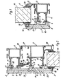
- Fig. 1 eine Festverglasung im Schnitt,
- Fig. 2 ein Fenster oder eine Tür im Horizontalschnitt,
- Fig. 3 eine konstruktive Einzelheit,
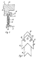
- Fig. 4 in schaubildlicher Darstellung die Ecke eines Blend- und Flügelrahmens in demontiertem Zustand,
- Fig. 5 eine Ansicht in Richtung des Pfeiles V in Fig. 4 und
- Fig. 6 eine mit einem Eckverbinder nach der Fig. 5 versehene Festverglasung.
- Die Festverglasung 1, das Fenster oder die Tür weisen wärmegedämmte Profilrahmen 1, die aus einem Metallaußenprofil 2, einem Metallinnenprofil 3 und aus mindestens einem aus einem Wärmeisolierwerkstoff gefertigten Isolierstab 4 bestehen, der zwischen den Metallprofilen angeordnet und mit diesen verbunden ist. Die Verbindung der Isolierstäbe 4 mit dem Metallaußenprofil und dem Metallinnenprofil erfolgt im Fügeverfahren. Zu diesem Zweck werden die im Querschnitt trapezförmigen Randleisten 5 der Isolierstäbe 4 von Verankerungsnuten der Metallprofile aufgenommen, die jeweils durch einen Anformsteg 6 und einen Steg 7 begrenzt werden, der bei der Anformung des Steges 6 an den Isolierstab 4 als Widerlager dient.
- Die Metallaußenprofile 2 der Festverglasung nach der Fig. 1 sowie des Blendrahmens und des Flügelrahmens nach der Fig. 2 sind als schußhemmende oder schußsichere, plattenförmige, stranggepreßte Profile ausgebildet, die an der Innenseite balkenförmige Tragleisten 8 aufweisen. Einstückig mit diesem balkenförmigen Tragleisten sind die Stege 6 und 7, die die Verankerungsnuten für die Randleisten 5 der Isolierstäbe 4 begrenzen. Zwei benachbarte Tragleisten 8 bilden zusammen mit der Innenfläche 9 des Metallaußenprofils 2 eine C-förmig begrenzte Aufnahmenut 10 für einen Eckverbinder 11, der in der Fig. 2 in strichpunktierten Linien angedeutet ist. Das Metallaußenprofil des Flügelrahmens des Fensters oder der Tür ist ferner mit einer Verankerungsnut 12 für ein am Rand der Scheibe 13 anliegendes Dichtungsprofil 14 ausgerüstet. Auch bei dem Metallaußenprofil 2 der in der Fig. 1 dargestellten Festverglasung ist für das am Rand der Scheibe 13 anliegende Dichtungsprofil 15 eine Verankerungsnut 16 vorgesehen.
- In der Kammer 17 zwischen dem Blendrahmen und dem Flügelrahmen des Fensters oder der Tür ist eine am Blendrahmen festgelegte Mitteldichtung 18 angeordnet, die in der Verschlußstellung des Fensters oder der Tür mit ihrer Dichtlippe 19 an einem Anschlagsteg 20 des Isolierstabes 4 anliegt.
- Aus der Fig. 2 ergibt sich auch, daß in der Verschlußstellung des Fensters oder der Tür die Außenflächen 21 des Blendrahmens und 22 des Flügelrahmens miteinander fluchten. Ferner folgt aus der Fig. 2, daß im Überlappungsbereich des Blend- und des Flügelrahmens das Metallaußenprofil des Flügelrahmens eine Tragleiste 8 aufweist, wodurch dieser Überlappungsbereich verstärkt wird. Die Außenwandung 23 des Metallaußenprofils 2 weist eine Mindestdicke von 5 mm auf. Die Dicke dieser Außenwandung 23 kann auch 30 und mehr mm betragen. Das Metallaußenprofil wird vorteilhaft aus einer Aluminiumspeziallegierung mit einem Legierungsbestandteil Silicium zwischen 0,6 bis 0,8 Prozent und einem Legierungsanteil Magnesium gefertigt. Durch diese Materialwahl ist die Eloxierbarkeit des Metallaußenprofils 2 gegeben. Das Metallaußenprofil, das aus der genannten Legierung gefertigt wird, ist zäh-hart, so daß auch ein Anformen der Stege 6 an die Isolierstäbe 4 möglich ist, ohne daß Risse im Fußbereich des Anformsteges auftreten.
- Das in den Fig. 1 und 2 aufgezeigte Metallinnenprofil 3 weist zwei Verankerungsnuten für die parallel zueinander verlaufenden beiden Isolierstäbe 4 auf, wobei diese Verankerungsnuten ebenfalls durch einen Anformsteg 24 und einen Steg 25 begrenzt werden, der beim Anformen des Steges 24 ein Widerlager bildet. Als Metallinnenprofile 3 werden handelsübliche Aluminiumprofile verwendet. An dem Metallinnenprofil ist eine Glashalteleiste 26 bzw. 27 befestigt, die ein am Rand der Scheibe 13 anliegendes Dichtungsprofil 28 bzw. 29 trägt. An dem Metallinnenprofil 3 des Flügelrahmens des Fensters oder der Tür nach der Fig. 2 ist ein Dichtungsprofil 30 befestigt, das in der Verschlußstellung des Flügels eine Anschlagdichtung bildet.
- Bei dem Ausführungsbeispiel nach der Fig. 3 bestehen die im Querschnitt etwa trapezförmigen Randleisten 31 des Isolierstabes 4 aus einem harten Material, während der Mittelbereich des Isolierstabes aus relativ weichem Isoliermaterial gefertigt ist. Hierdurch kann die Elastizität des Isolierstabes erhöht und damit die Wirkung der Verbundkonstruktion bei einem Beschuß des Metallaußenprofils 2 verbessert werden. Der Isolierstab 4 ist in seinem mittleren Bereich im dargestellten Ausführungsbeispiel hohl ausgebildet, weist also eine Innenkammer 32 auf, so daß sich bei einem Beschuß des Metallaußenprofils 2 die Wandungen 33 der Kammer nach außen verformen und die in der Fig. 3 strichpunktiert angedeutete Lage einnehmen können. Durch diese Gestaltung des Isolierstabes 4 ist der Profilrahmen in Längsrichtung formstabil und in Querrichtung elastisch.
- In den Fig. 4, 5 und 6 ist ein weiteres Ausführungsbeispiel für die Gestaltung der auf Gehrung geschnittenen Rahmenecken der Verbindprofile und der Eckverbinder dargestellt.
- Die Eckverbinder 11 überdecken den Gehrungsspalt des Metallaußenprofils 2 eines fertigen Fensters oder einer Tür ausschließlich im Bereich zwischen den balkenförmigen Tragleisten 8.
- Um die Sicherheit gegen einen Durchschuß im gesamten Bereich der Profilrahmengehrung zu erhöhen, wird der Eckverbinder 11 gemäß den Fig.4,5 und 6 mit einer pfeilförmigen Gehrungsversteifung 34 versehen. Diese Gehrungsversteifung 34 sowie der Eckverbinder 11 bestehen aus einer hochfesten Aluminiumlegierung und sind zu einer Baueinheit verbunden. Die Verbindung beider Teile erfolgt durch ein Niet 40, durch eine Verklebung oder durch eine Punktschweißung. Die Ausrichtung der Gehrungsversteifung 34, die vorteilhaft als Blech ausgebildet ist, zum Eckverbinder 11 erfolgt unter einem Winkel von 45° zu den Eckverbinderschenkeln 41, 42.
- Dieses als Eckverbinder und als Gehrungsversteifung verwendete Bauteil wird in die Gehrung der Metallaußenprofile des Blendrahmens 43 und des Flügelrahmens 44 eingesetzt, wobei zuvor im Gehrungsbereich eines jeden Metallaußenprofils eine nutförmige Ausnehmung 35 durch eine Ausfräsung eingearbeitet wird. Die Tiefe der nutförmigen Ausnehmung 35 entspricht der Gesamtdicke der Bauteile 11 und 34 und orientiert sich hinsichtlich seiner Lage zur Isolierzone des jeweiligen Verbundprofils an der Innenbegrenzung der Aufnahmenut 10.
- In der Fig. 6 ist die Lage des Eckverbinders und der daran befestigten Gehrungsversteifung 34 dargestellt. Die nutförmigen Ausnehmungen 35 im Blend- und im Flügelrahmen sind in der Fig. 2 in gestrichelten Linien dargestellt.
- Dadurch, daß die Gehrungsversteifung 34 in eine nutförmige Ausnehmung des Metallaußenprofils 2 eingeschoben wird, kann sich die als Blech ausgebildete Gehrungsversteifung unter Belastung auf den verbleibenden Tragleisten 8 in diesem Bereich abstützen und die Last über die Isolierleisten 4 auf die innere Fensterkonstruktion abtragen. Der Vorteil dieser Konzeption liegt darin, daß die pfeilförmigen Gehrungsversteifungen 34 den Gehrungsbereich verdeckt liegend absichern und daß die Position dieser Gehrungsversteifung durch die feste Verbindung mit dem Eckverbinder 11 ohne einen besonderen Aufwand sichergestellt ist.
- Der Eckverbinder 11 wird ebenfalls aus einer hochfesten Aluminiumlegierung gefertigt und verfügt über ausgestanzte Nuten 36, die dazu dienen, die unteren Teile von Befestigungsstiften 37 aufzunehmen, durch die die Eckverbinder mit den äußeren, beschußhemmenden Metallaußenprofilen mechanisch verbunden werden. Die Befestigungsstifte 37 werden in Bohrungen 38 der Metallaußenprofile 2 eingetrieben, die im Gehrungsbereich der genannten Profile vorgesehen sind und die zu den Nuten 36 der Eckverbinderschenkel einen Versatz aufweisen. Durch diesen Versatz wird beim Eintreiben eines Befestigungsstiftes 37 in die zugeordnete Nut 36 eines Eckverbinderschenkels eine Kraftkomponente erzeugt, die ein Zusammenpressen der Gehrungsflächen der Metallaußenprofile 2 bewirkt. Die Nuten 36 weisen eine schräge Anlauffase 39 auf. Durch die Zuordnung der pfeilförmigen Gehrungsversteifung 34 zu jedem Eckverbinder 11 ist der Gehrungsbereich des Fenster- oder des Türrahmens oder des Rahmens der Festverglasung besonders gesichert, da die Profilgehrung voll unterlegt ist und durch die Eckverbinderbefestigung auch ein Auseinanderspreizen der Gehrung durch direkt in den Gehrungsspalt einschlagende Geschosse verhindert wird.
Claims (8)
Priority Applications (1)
| Application Number | Priority Date | Filing Date | Title |
|---|---|---|---|
| AT85116250T ATE42797T1 (de) | 1985-02-14 | 1985-12-19 | Fenster oder tuer bzw. festverglasung mit einer schusssicheren scheibe. |
Applications Claiming Priority (2)
| Application Number | Priority Date | Filing Date | Title |
|---|---|---|---|
| DE3504989A DE3504989C2 (de) | 1985-02-14 | 1985-02-14 | Verglasung mit einer schußsicheren Scheibe |
| DE3504989 | 1985-02-14 |
Publications (3)
| Publication Number | Publication Date |
|---|---|
| EP0191190A2 EP0191190A2 (de) | 1986-08-20 |
| EP0191190A3 EP0191190A3 (en) | 1987-05-13 |
| EP0191190B1 true EP0191190B1 (de) | 1989-05-03 |
Family
ID=6262461
Family Applications (1)
| Application Number | Title | Priority Date | Filing Date |
|---|---|---|---|
| EP85116250A Expired EP0191190B1 (de) | 1985-02-14 | 1985-12-19 | Fenster oder Tür bzw. Festverglasung mit einer schusssicheren Scheibe |
Country Status (6)
| Country | Link |
|---|---|
| EP (1) | EP0191190B1 (de) |
| AT (1) | ATE42797T1 (de) |
| DE (2) | DE3504989C2 (de) |
| DK (1) | DK164187C (de) |
| FI (1) | FI81174C (de) |
| NO (1) | NO164314C (de) |
Families Citing this family (10)
| Publication number | Priority date | Publication date | Assignee | Title |
|---|---|---|---|---|
| IT1215385B (it) * | 1987-03-17 | 1990-02-08 | Aluminia Spa | Serramento blindato antiproiettile integrale in lega di alluminio a doppio scudo. |
| IE59197B1 (en) * | 1987-04-07 | 1994-01-26 | Thermal Profiles Accessories | Frame member for supporting a door and a window |
| DE3728247C1 (de) * | 1987-08-25 | 1988-09-01 | Elke Saelzer | Verbundprofil fuer Rahmenschenkel oder Sprossen |
| DE4330292C2 (de) * | 1993-09-07 | 1999-02-25 | Sommer Metallbau Stahlbau Gmbh | Rahmenprofil, insbesondere Aluminiumrahmenprofil, für Sicherheitsfenster, -Türen oder Wandelemente |
| DE102004007164A1 (de) * | 2004-02-12 | 2005-09-22 | Sälzer Sicherheitstechnik GmbH | Sprengwirkungshemmendes Doppelfenster |
| EP3034732B1 (de) * | 2014-12-17 | 2021-02-17 | dormakaba Deutschland GmbH | Faltflügeltüranlage |
| EP3034733B1 (de) * | 2014-12-17 | 2022-06-01 | dormakaba Deutschland GmbH | Faltflügeltüranlage |
| CN114482782B (zh) * | 2022-01-20 | 2022-08-23 | 华茗设计集团有限公司 | 一种被动式超低能耗建筑外窗及其实施方法 |
| CN115929170B (zh) * | 2022-12-28 | 2025-08-15 | 临沂市鸿泰门窗有限公司 | 一种高密封铝合金窗 |
| DE102023123090A1 (de) * | 2023-08-28 | 2025-03-06 | SCHÜCO International KG | Fassadenelement und Elementfassade |
Family Cites Families (8)
| Publication number | Priority date | Publication date | Assignee | Title |
|---|---|---|---|---|
| DE1101734B (de) * | 1955-08-29 | 1961-03-09 | Aluminium Ind Ag | Verfahren zur Herstellung eines Winkelprofils aus Metall mit einer Kunststoffzwischenlage in Stabform, insbesondere fuer Fenster- oder Tuerrahmen |
| DE7717021U1 (de) * | 1977-05-28 | 1977-09-08 | Schueco Heinz Schuermann Gmbh & Co, 4800 Bielefeld | Basisprofil fuer den blendrahmen eines holz- oder kunststoffensters oder einer holz- oder kunststofftuer |
| DE7803666U1 (de) * | 1978-05-24 | 1978-05-24 | Schueco Heinz Schuermann Gmbh & Co, 4800 Bielefeld | |
| DE2828905C2 (de) * | 1978-06-30 | 1982-05-13 | Schalm, Wolfgang, 8000 München | Verbundprofil bestehend aus zwei zueinander parallelen Metallteilen |
| DE8007525U1 (de) * | 1980-03-19 | 1980-07-24 | Goetz Metallbau Gmbh, 8360 Deggendorf | BeschuBhemmendes Metallfenster |
| DE8016077U1 (de) * | 1980-06-18 | 1980-11-13 | Rema Metall- Und Apparatebau Gmbh, 3000 Hannover | Beschußfestes Fenster |
| DE3025706A1 (de) * | 1980-07-07 | 1982-01-28 | Eberhard 7121 Freudental Keller | Vorrichtung zur herstellung von verbundprofilen, insbesondere fuer fenster, tueren o.dgl. |
| DE8022687U1 (de) * | 1980-08-26 | 1980-11-27 | Saelzer, Heinrich, 3550 Marburg | Kippfluegellager fuer fenster oder tueren schwerer ausfuehrung |
-
1985
- 1985-02-14 DE DE3504989A patent/DE3504989C2/de not_active Expired
- 1985-12-19 EP EP85116250A patent/EP0191190B1/de not_active Expired
- 1985-12-19 DE DE8585116250T patent/DE3569955D1/de not_active Expired
- 1985-12-19 AT AT85116250T patent/ATE42797T1/de not_active IP Right Cessation
-
1986
- 1986-02-11 FI FI860614A patent/FI81174C/fi not_active IP Right Cessation
- 1986-02-13 NO NO860532A patent/NO164314C/no not_active IP Right Cessation
- 1986-02-13 DK DK069186A patent/DK164187C/da not_active IP Right Cessation
Also Published As
| Publication number | Publication date |
|---|---|
| NO164314C (no) | 1990-09-19 |
| FI81174C (fi) | 1990-09-10 |
| FI860614A0 (fi) | 1986-02-11 |
| FI860614A7 (fi) | 1986-08-15 |
| DK164187C (da) | 1992-10-05 |
| ATE42797T1 (de) | 1989-05-15 |
| NO860532L (no) | 1986-08-15 |
| DE3504989A1 (de) | 1986-08-14 |
| DK69186A (da) | 1986-08-15 |
| DE3504989C2 (de) | 1987-04-09 |
| DK164187B (da) | 1992-05-18 |
| DE3569955D1 (en) | 1989-06-08 |
| EP0191190A3 (en) | 1987-05-13 |
| NO164314B (no) | 1990-06-11 |
| EP0191190A2 (de) | 1986-08-20 |
| DK69186D0 (da) | 1986-02-13 |
| FI81174B (fi) | 1990-05-31 |
Similar Documents
| Publication | Publication Date | Title |
|---|---|---|
| EP0614018B1 (de) | T-Verbindung zwischen zwei Profilen | |
| EP0636760B1 (de) | Rahmen füe ein Fenster, einer Tür oder Fassade | |
| EP0569986B1 (de) | Verbindung für winklig aneinanderstossende Hohlprofilstäbe | |
| DE2608325C3 (de) | Mehrteiliger, wärmegedämmter Metallprofilstab zum Befestigen von Wand- und Fensterelementen | |
| DE2915255A1 (de) | Verbundprofil | |
| DE202014010902U1 (de) | Isolierelement für Fassaden- oder Lichtdachkonstruktionen | |
| EP0191190A2 (de) | Fenster oder Tür bzw. Festverglasung mit einer schusssicheren Scheibe | |
| DE3532593A1 (de) | Extrudierter kunststoffhohlprofilstab fuer rahmen von fenstern und tueren | |
| DE2300281A1 (de) | Verstaerkungs-winkel fuer eckverbindungen von fenstern, tueren und aehnlichen bauteilen aus kunststoffprofilen zur erhoehung der stabilitaet und gestaltfestigkeit | |
| DE2313662A1 (de) | Fenster und verfahren zu seiner herstellung | |
| DE2927463A1 (de) | Fassadenwand | |
| DE202005013103U1 (de) | Tragprofilkonstruktion mit Isolatorprofil | |
| DE20122533U1 (de) | Fensterrahmen oder Fensterflügel | |
| DE2750351A1 (de) | Profilkonstruktion | |
| DE7018201U (de) | Schiebefenster. | |
| DE19851658A1 (de) | Fenster, Tür, Fassadenelement oder dergleichen sowie Verfahren zu deren Herstellung | |
| DE9206375U1 (de) | Tragwerk für Glasfassaden, -wände und/oder -dächer | |
| EP0247356A2 (de) | Verglasung für Gewächshäuser, Wintergärten oder dergleichen sowie dabei verwendbare Glasscheibe | |
| WO1994025717A1 (de) | Mit einer füllung versehener flügel, insbesondere fenster- oder türflügel und verfahren zu dessen herstellung | |
| DE4027335A1 (de) | Halterungsanordung fuer glasscheiben in toren | |
| DE1940733A1 (de) | Stranggepresstes Hohlprofil | |
| DE2553801A1 (de) | Rahmenkonstruktion fuer tueren, fenster u.dgl. | |
| DE3528388A1 (de) | Elastische profildichtung fuer isolierverglasungen | |
| DE2642746A1 (de) | Aus kunststoffschaum mit eingelagerten metallenen hohlprofilen bestehender rahmen fuer fenster | |
| AT249337B (de) | Fenster bzw. Tür |
Legal Events
| Date | Code | Title | Description |
|---|---|---|---|
| PUAI | Public reference made under article 153(3) epc to a published international application that has entered the european phase |
Free format text: ORIGINAL CODE: 0009012 |
|
| AK | Designated contracting states |
Kind code of ref document: A2 Designated state(s): AT BE CH DE FR GB IT LI NL SE |
|
| PUAL | Search report despatched |
Free format text: ORIGINAL CODE: 0009013 |
|
| AK | Designated contracting states |
Kind code of ref document: A3 Designated state(s): AT BE CH DE FR GB IT LI NL SE |
|
| 17P | Request for examination filed |
Effective date: 19870407 |
|
| 17Q | First examination report despatched |
Effective date: 19880413 |
|
| RAP1 | Party data changed (applicant data changed or rights of an application transferred) |
Owner name: SCHUECO INTERNATIONAL GMBH & CO. |
|
| ITF | It: translation for a ep patent filed | ||
| GRAA | (expected) grant |
Free format text: ORIGINAL CODE: 0009210 |
|
| AK | Designated contracting states |
Kind code of ref document: B1 Designated state(s): AT BE CH DE FR GB IT LI NL SE |
|
| REF | Corresponds to: |
Ref document number: 42797 Country of ref document: AT Date of ref document: 19890515 Kind code of ref document: T |
|
| GBT | Gb: translation of ep patent filed (gb section 77(6)(a)/1977) | ||
| REF | Corresponds to: |
Ref document number: 3569955 Country of ref document: DE Date of ref document: 19890608 |
|
| ET | Fr: translation filed | ||
| PLBE | No opposition filed within time limit |
Free format text: ORIGINAL CODE: 0009261 |
|
| STAA | Information on the status of an ep patent application or granted ep patent |
Free format text: STATUS: NO OPPOSITION FILED WITHIN TIME LIMIT |
|
| 26N | No opposition filed | ||
| ITTA | It: last paid annual fee | ||
| EAL | Se: european patent in force in sweden |
Ref document number: 85116250.3 |
|
| PGFP | Annual fee paid to national office [announced via postgrant information from national office to epo] |
Ref country code: SE Payment date: 19991220 Year of fee payment: 15 |
|
| PG25 | Lapsed in a contracting state [announced via postgrant information from national office to epo] |
Ref country code: SE Free format text: LAPSE BECAUSE OF NON-PAYMENT OF DUE FEES Effective date: 20001220 |
|
| EUG | Se: european patent has lapsed |
Ref document number: 85116250.3 |
|
| REG | Reference to a national code |
Ref country code: GB Ref legal event code: IF02 |
|
| PGFP | Annual fee paid to national office [announced via postgrant information from national office to epo] |
Ref country code: GB Payment date: 20021126 Year of fee payment: 18 |
|
| PGFP | Annual fee paid to national office [announced via postgrant information from national office to epo] |
Ref country code: DE Payment date: 20021206 Year of fee payment: 18 |
|
| PGFP | Annual fee paid to national office [announced via postgrant information from national office to epo] |
Ref country code: NL Payment date: 20021217 Year of fee payment: 18 Ref country code: FR Payment date: 20021217 Year of fee payment: 18 |
|
| PGFP | Annual fee paid to national office [announced via postgrant information from national office to epo] |
Ref country code: AT Payment date: 20021223 Year of fee payment: 18 |
|
| PGFP | Annual fee paid to national office [announced via postgrant information from national office to epo] |
Ref country code: CH Payment date: 20021224 Year of fee payment: 18 |
|
| PGFP | Annual fee paid to national office [announced via postgrant information from national office to epo] |
Ref country code: BE Payment date: 20030107 Year of fee payment: 18 |
|
| PG25 | Lapsed in a contracting state [announced via postgrant information from national office to epo] |
Ref country code: GB Free format text: LAPSE BECAUSE OF NON-PAYMENT OF DUE FEES Effective date: 20031219 Ref country code: AT Free format text: LAPSE BECAUSE OF NON-PAYMENT OF DUE FEES Effective date: 20031219 |
|
| PG25 | Lapsed in a contracting state [announced via postgrant information from national office to epo] |
Ref country code: LI Free format text: LAPSE BECAUSE OF NON-PAYMENT OF DUE FEES Effective date: 20031231 Ref country code: CH Free format text: LAPSE BECAUSE OF NON-PAYMENT OF DUE FEES Effective date: 20031231 Ref country code: BE Free format text: LAPSE BECAUSE OF NON-PAYMENT OF DUE FEES Effective date: 20031231 |
|
| BERE | Be: lapsed |
Owner name: *SCHUCO INTERNATIONAL G.M.B.H. & CO. Effective date: 20031231 |
|
| PG25 | Lapsed in a contracting state [announced via postgrant information from national office to epo] |
Ref country code: NL Free format text: LAPSE BECAUSE OF NON-PAYMENT OF DUE FEES Effective date: 20040701 Ref country code: DE Free format text: LAPSE BECAUSE OF NON-PAYMENT OF DUE FEES Effective date: 20040701 |
|
| GBPC | Gb: european patent ceased through non-payment of renewal fee |
Effective date: 20031219 |
|
| REG | Reference to a national code |
Ref country code: CH Ref legal event code: PL |
|
| PG25 | Lapsed in a contracting state [announced via postgrant information from national office to epo] |
Ref country code: FR Free format text: LAPSE BECAUSE OF NON-PAYMENT OF DUE FEES Effective date: 20040831 |
|
| NLV4 | Nl: lapsed or anulled due to non-payment of the annual fee |
Effective date: 20040701 |
|
| REG | Reference to a national code |
Ref country code: FR Ref legal event code: ST |