EP0187966B1 - Heizgerät mit Wärmespeicheranordnung - Google Patents
Heizgerät mit Wärmespeicheranordnung Download PDFInfo
- Publication number
- EP0187966B1 EP0187966B1 EP85115887A EP85115887A EP0187966B1 EP 0187966 B1 EP0187966 B1 EP 0187966B1 EP 85115887 A EP85115887 A EP 85115887A EP 85115887 A EP85115887 A EP 85115887A EP 0187966 B1 EP0187966 B1 EP 0187966B1
- Authority
- EP
- European Patent Office
- Prior art keywords
- heat storage
- housing
- storage device
- heating apparatus
- heat
- Prior art date
- Legal status (The legal status is an assumption and is not a legal conclusion. Google has not performed a legal analysis and makes no representation as to the accuracy of the status listed.)
- Expired
Links
Images


Classifications
-
- D—TEXTILES; PAPER
- D06—TREATMENT OF TEXTILES OR THE LIKE; LAUNDERING; FLEXIBLE MATERIALS NOT OTHERWISE PROVIDED FOR
- D06F—LAUNDERING, DRYING, IRONING, PRESSING OR FOLDING TEXTILE ARTICLES
- D06F75/00—Hand irons
- D06F75/08—Hand irons internally heated by electricity
- D06F75/24—Arrangements of the heating means within the iron; Arrangements for distributing, conducting or storing the heat
-
- C—CHEMISTRY; METALLURGY
- C09—DYES; PAINTS; POLISHES; NATURAL RESINS; ADHESIVES; COMPOSITIONS NOT OTHERWISE PROVIDED FOR; APPLICATIONS OF MATERIALS NOT OTHERWISE PROVIDED FOR
- C09K—MATERIALS FOR MISCELLANEOUS APPLICATIONS, NOT PROVIDED FOR ELSEWHERE
- C09K5/00—Heat-transfer, heat-exchange or heat-storage materials, e.g. refrigerants; Materials for the production of heat or cold by chemical reactions other than by combustion
- C09K5/02—Materials undergoing a change of physical state when used
- C09K5/06—Materials undergoing a change of physical state when used the change of state being from liquid to solid or vice versa
- C09K5/063—Materials absorbing or liberating heat during crystallisation; Heat storage materials
-
- Y—GENERAL TAGGING OF NEW TECHNOLOGICAL DEVELOPMENTS; GENERAL TAGGING OF CROSS-SECTIONAL TECHNOLOGIES SPANNING OVER SEVERAL SECTIONS OF THE IPC; TECHNICAL SUBJECTS COVERED BY FORMER USPC CROSS-REFERENCE ART COLLECTIONS [XRACs] AND DIGESTS
- Y10—TECHNICAL SUBJECTS COVERED BY FORMER USPC
- Y10S—TECHNICAL SUBJECTS COVERED BY FORMER USPC CROSS-REFERENCE ART COLLECTIONS [XRACs] AND DIGESTS
- Y10S165/00—Heat exchange
- Y10S165/902—Heat storage
Definitions
- the present invention relates to a heating apparatus which has a heat storage device and is usable without electric cord.
- the addition of the heat storage function to the heating apparatuses of this type is accomplished by increasing their heat capacity due to their specific heat.
- the latter is increased by increasing the weight of their heating base and they are usually provided with heat storage substances which have latent heats at specified temperatures.
- the heat storage substances used in these heating apparatuses need to be capable of storing and discharging heat within a temperature range of 150-250°C and especially to have a high safety margin, for its environment of use is often the household.
- the present inventors focused their attention to pentaerythritol as the heat storage material for this purpose.
- Pentaerythritol has its crystal transition point at 188°C, its latent heat of transition is as large as about 300 j/ g, and pentaerythritol itself is widely used in large amounts as raw material of resins and paints, and therefore is readily available.
- pentaerythritol is known to gradually lose heat storage capacity due to degradation from oxidation, when exposed to high temperature in air for a long time, and it has been demonstrated that particularly at such high temperatures as above 200°C even in a closed system isolated from ambient air the presence in the system of substances incompatible with pentaerythritol likewise results in loss of the heat storage capacity.
- the housing which contains the heat storage substance is normally composed of metal in order to ensure high heat resistance, high thermal conductivity and mass production capacity, etc.
- the aforementioned results point to the inadequacy of metal for the housing which contains pentaerythritol in view of the adverse effect on its durability, thus raising a problem in practical application of pentaerythritol as a heat storage substance.
- Another problem consists in that if pentaerythritol is completely enclosed in a housing for prevention of its deterioration from oxygen, as above described, its degradation still occurs after use for a long period, even though the housing is composed of a nonmetal substance which is highly compatible with this material.
- the gas formed by the decomposition gradually accumulates inside the housing and involves the hazard that internal pressure in the housing will continue to rise.
- the present invention is intended to solve the aforementioned problems and has as its object a highly safe heating apparatus in which no accelerated deterioration of pentaerythritol will take place, even when being contained in a metal housing, ensuring its durability over a long time and moreover, which dismisses with the fear of causing internal pressure rise even during long periods of use.
- the heating apparatus with a heat storage device and a heating element according to the invention comprises:
- the fluororesin which is inert to pentaerythritol not only prevents the contact with the material of the housing surface thereby preventing reduction in the heat storage capacity of pentaerythritol, but even during long-period use, there is no fear of an abnormal rising of the internal pressure, because the decomposition gas gradually is discharged thanks to the proper permeability of the fluororesin. Therefore a heating apparatus having a heat storage function and a guaranteed safety and long life may be realized.
- Preferred representatives for use as the aforementioned olefinic polymers are ethylene polymers, proplylene polymers, and methylene polymers.
- fluorine-resin polymers there are preferred tetrafluoroethylene polymers, tetrafluoroethylene-perfluoralkyl vinyl ether copolymers, tetrafluoroethylene-hexafluoropropylene copolymers, tetrafluoroethylene-ethylene copolymers and vinylidene fluoride polymers.
- paraffin wax there are preferred paraffin waxes, microcrystalline waxes and petroleum, each having a carbon number of at least 16.
- a vaporizing chamber in the housing cover.
- the housing includes an internal bottom surface and a top opening closed by a removable housing cover, and
- the aforementioned heat storage elements are stacked and at least one heat transferring plate is indirect or by means of a heat conductive material in direct thermal contact with at least one of the base and the housing cover which heat transferring plate is provided between respective heat storage elements.
- the container is formed in an undulated shape and is securely pinched between and in contact with the housing and the housing cover which mate with the undulations of the container.
- the housing has an opening with a peripheral rim and the container comprises a fluororesin coating formed on the inside surface of said housing and the housing includes a removable housing cover mounted on said rim to seal said opening.
- the fluoresin coating preferably is formed on at least the part of the aforementioned housing cover which abuts on the opening peripheral rim of the housing.
- Fig. 1 shows a heating apparatus having a heat storage device embodying this invention.
- a metal base 1 has a heating surface 2 at its top part and a housing 3 at the lower part.
- a heat storage substance comprising pentaerythritol as its main ingredient is contained in a container 5 made of a fluororesin which is provided in the housing 3.
- a sheet 6 of silicone rubber is provided for securing the container 5 located in the housing 3.
- the silicone rubber sheet is formed by applying liquid silicone rubber on the opening of the housing 3 in such a way as to coat it and subsequently set.
- a heating element 7 for heating the substance 4 is installed in a part of the base 1 above the housing 3. Since the substance 4 is hermetically sealed in the container 5, the substance 4 is not exposed to air.
- the container 5 is formed of the fluororesin which is inert to the substance 4 so as to isolate substance 4 from the housing 3, it prevents the substance 4 from direct contact with the housing; therefore, the heat storage capacity of the substance 4 will not be degraded by contact with metal, even if the substance 4 continues to be heated for a long time at temperatures higher than its heat storage temperature.
- Fig. 2 illustrates experimental results indicating that only a fluororesin, when compared with various types of heat-resistant resins, is inert to pentaerythritol.
- the method of the experiment comprises sealing pentaerythritol and a test piece of each heat resistant resin in respective glass tubes, then subjecting them to a continuous heating test at a temperature of 220°C, and measuring the changes of the heat storage capacity of each sample.
- curve A illustrates a case wherein the tube only pentaerythritol is enclosed;
- curve B is for a case wherein in the tube pentaerythritol is mixed with fluororesin (PTFE);
- curve C is for a case wherein the pentaerythritol is mixed with an epoxy resin;
- curve D is for a case wherein the pentaerythritol is mixed with a polyimide resin;
- curve E is for a case wherein the pentaerythritol is mixed with a polyamide resin (nylon 66). All resins other than the fluororesin of curve B, being poorly compatible with pentaerythritol, caused a reduction in its heat storage capacity.
- PFTE tetrafluoroethylene resin
- PFE tetrafluoroethylene-perfluoroalkyl vinyl ether copolymer resin
- FEP tetrafluoroethylene hexafluoropropylene copolymer resin
- fluororesins show high gas permeabilities, and even when the container 5 is completely enclosed by way of welding, the gas generated in the container 5 is gradually discharged. Accordingly, even if deterioration of the heat storage substance 4 has advanced after a long period of use, the internal pressure of the container 5 will not increase abnormally.
- Fig. 3 shows the gas permeabilities of different resins.
- the graph reveals that the fluororesin provides a high gas permeability, thus testifying its high gas transmitting property. Rubber generally gives high permeability and silicone rubber is no exception, its gas permeability being very high.
- the container 5 for the heat storage substance 5 is covered with a sheet of silicone rubber and secured in the housing as in this embodiment, not only the gas permeability between this container 5 inside the housing and ambient air may be maintained, but also various degrees of gas permeability are obtainable by altering the thickness of the silicone rubber 6 in correspondence with the size of the opening of the housing 3.
- this substance 4 is prepared by mixing less than 70 weight % of at least one olefinic polymer and/or fluorine-resin polymer and/or less than 70 weight % of petroleum waxes having a carbon number of at least 16 (provided that the total amount of these mixing components falls within a range of more than 1 but less than 70 weight %) with 30-99 weight % of pentaerythritol; it is manufactured by heating, when mixing them, at temperatures higher than the melting points of the petroleum waxes.
- the pentaerythritol of industrial grade contains mixed therein dipentaerythritol and bispentaerythritol monoformal condensate, both being a reaction-by-product in synthesis, and salts of organic acids which are used as synthetic catalysts, these salts being formed as neutralization products with sodium hydroxide, potassium hydroxide, etc.
- the melting point of pentaerythritol is essentially lower than 260°C which is its intrinsic value (for example, the melting point is about 200°C when the pentaerythritol content is around 95 weight %).
- hitherto pentaerythritol is not only molten by heating it near its phase transition temperature, but also when it is intended to be used as a heat storage substance by being held at temperatures above its phase transition temperature for a long time; then its decomposition proceeds within a short period, and hence, its heat storage property is lost.
- the surface part of the pentaerythritol crystal particles with the olefinic polymer or fluorine-resin polymer and the petroleum wax during the heating to above its phase transition temperature, it is possible to selectively eliminate from the surfaces of its crystal grains interfering factors.
- Novatek L (Trade name of a low-density polyethylene resin, manufactured by Mitsubishi Chemical Industries, Ltd.) was used as a low-density ethylene polymer, which was pulverized to have 1-10 pm particle diameters and Pentalit M (Trade name of Pentaerythritol manufactured by Koei Chemical Co., Ltd., total amount of dipentaerythritol and bispentaerythritol condensate is 0.6 weight %) are mixed at different weight ratios for 100 weight parts of the total mixture (see Experiment Nos. 1 to 7 in Table 1).
- the individual samples were put in separate glass beakers and vigorously stirred while heating at 150°C from outside, and the resultant crystal grain surface of the pentaerythritol was thereby subjected to a coating treatment with ethylene polymer. After cooling each sample, 10 g of it was taken and pressed at a pressure of 700 kg/cm 2 to form a plate 40 mm in diameter. The plate was set on a petri dish having an inside diameter of 40 mm and made of glass. A single liquid thermosetting silicone rubber was applied to the gap or clearance part between the plate and the glass cover, and was then heated at 150°C for 30 minutes to be set, thus effecting hermetic sealing; in that way, samples for long heating stability tests were manufactured.
- Comparison sample-1 containing only pentaerythritol which is measured after the stability test at 230°C and at a 500 hr long heating time showed notably inferior results, as compared with its initial characteristics, and the heat storage substances turned into a browny resinified state.
- Comparison sample-2 has better thermal stability than Comparison sample-1, but is not in a practically usable state.
- Samples Nos. 1-6 though showing decreases in the heat of phase transition corresponding to the amounts of Novatek L added, give adequate results even after the 230°Cx500 hr long heating stability test, and the discoloration degrees of the heat storage substance are very low.
- HNP-9 manufactured by Nippon Seiro Co., Ltd.; melting point 65°C and carbon numbers 25-35
- this wax and pentaerythritol were mixed in the ratios for the total of 100 weight parts of Experiments Nos. 8-14 as shown in Table 2.
- long heating stability test samples were prepared by the similar treatments as in the foregoing Example-A. These samples were put in a 230°C ⁇ 2°C thermostat container and taken out later a lapse of 500 hr and after observing the state of discoloration of the heat storage substance, the heat of phase transition (J/g) of the heat discharging side and the phase transition temperature were measured.
- Viscol 550P (Trade name, manufactured by Sanyo Chemical Industries, Ltd.; white powder, melting point 150°C, mean molecular weight 4,000) a low molecular weight propylene polymer, Microcrystalline wax Hi-MiX-2095 (manufactured by Nippon Seiro Co., Ltd.; M.P. 96°C) a petroleum wax and pentaerythritol (the same product as in Example-A) were mixed at the ratios for the total of 100 weight parts indicated under Experiment Nos. 15-20 in Table 3, respectively. Thereafter, individual samples were put in separate glass beakers, and the long heating stability test samples were prepared by subjecting them to the similar treatments as in Example-A, while heating them at 120°C. Then the characteristics were measured by the similar methods as in Example-B. Results of the measurement are shown in Tables 3-(1) and 3-(2).
- Tetrafluoroethylene resin powder M-12 (Trade name, manufactured by Daikin Industries, Ltd.; mean molecular weight more than 1 million, particle diameter approx. 0.1-10 pm), a fluorine-resin polymer HNP-9 (the same product as in Example-B) a petroleum wax and a mixture of Pentalit M (the same product as in Example-A) and Pentalit (Trade name, manufactured by Koei Chemical Co., Ltd., containing 1.6 weight % in total of dipentaerythritol and bispentaerythritol monoformal condensate) in a ratio of 1:1 were mixed in the ratios for the total of 100 weight parts as indicated under Experiments Nos. 21 and 22 in Table 4, respectively. Thereafter, the mixture was treated in the similar way as in Example-B, thereby preparing long heating stability test samples. In the following, results of characteristics measured similarly as in Example-B are shown in Tables 4-(1) and 4-(2).
- Fig. 4 shows a second embodiment of this invention.
- containers each formed a bag made of 50-200 pm thick fluororesin film by way of thermal welding, in which the heat storage substance 4 is hermetically enclosed; in this example, the material 4 is provided in two superposed layers.
- Numeral 3 designates the housing and 7 the heating element, the housing 3 and the heating element 7 being the same as in Fig. 1.
- Numeral 8 designates a silicone such as silicone oil, silicone grease, silicone rubber, etc., interposed between the containers 5' and the housing 3, which not only helps to securely hold the containers 5' inside the housing 3, but also serves to upgrade thermal transfer between the containers and the housing.
- Numeral 9 designates a housing cover mounted on the opening of the housing 3, which helps to secure the containers 5' by mechanical pressure.
- the heat storage substance 4 With the heat storage substance 4 being sealed in a bag shape container 5' formed of fluororesin film by thermal welding, the heat storage substance is not brought in direct contact with ambient air and the metal of the housing 3, so that such influences cannot cause a reduction of its heat storage capacity. Even when the heat storage substance 4 degrades during long-period use, the internal pressure of the containers 5' will not continue rising, thanks to the gas permeability of the fluororesin. Moreover, not only the mass production capacity is increased by forming the containers 5' from the fluororesin film, but also a cost advantage may be achieved by making use of PTFE which is an inexpensive fluororesin, though its moldability is not high.
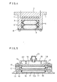
- Figs 5-7 represent a third embodiment in which the heating apparatus having a heat storage device of the present invention is applied to an iron.
- 10 denotes the iron base provided with a heating surface 11 and a housing 12 at its upper surface, in which a heating element 13 comprising a sheathed heater is embedded.
- Numeral 14 designates a housing cover in which a vaporizing chamber 15 is provided integrally therewith and which has this vaporizing chamber 15 formed on its upper surface.
- Numeral 16 stands for a flat plate-shaped heat storage element composed of a heat storage substance 17 of pentaerythritol as its main component which is coated with a fluororesin film.
- Numeral 19 is a heat transferring plate made of such a metal of high thermal conductivity as aluminum, or the like, which is not only in contact with the two heat storage elements 16, but also whose whole circumferential rim is held between the base 10 and the housing cover 14 and is thermally connected therewith.
- Numeral 20 shows a dripping nozzle, which is joined with the vaporizing chamber 15 through a packing 23 mounted on the vaporizing chamber cover 22 covering the top of the vaporizing chamber 15. Water in a tank 21 is supplied to the vaporizing chamber 15 through the dripping nozzle 20.
- Numeral 24 designates an opening-closing rod which is interlocked with a steam control button 26 located on top of the handle 25 and which is vertically movable to supply or stop water flow through the dripping nozzle 20.
- Numeral 27 denotes a steam ejecting port provided in the heating surface 11 of the base 10, which communicates with the vaporizing chamber 15 through a steam passage 28, through which the steam generated in the vaporizing chamber 15 is ejected.
- Numeral 29 designates a power supply terminal which is connected with the heat 13 through a thermoregulator and which is connected with a power source to supply power therethrough.
- Numeral 30 designates a temperature control lever joined with the thermoregulator, which is used for making the temperature setting of the base 10.
- the heating element 13 evolves heat, whereby the housing 12 in the base 10 and the housing cover 14 and the heat transferring plate 19 pinched therebetween are heated.
- the heat storage elements 16 are held between and in contact with the internal bottom surface 12a of the housing 12 and the inner surface of the housing cover 14 and are also in contact with the heat transferring plate 19. Therefore, each heat storage element 16 is heated from above and below over wide areas, so that heat be accumulated in the internal heat storage material 17 at high efficiency and in a short period.
- This material 17 which has stored heat starts heat discharging, after disconnecting of the power source from the power supply terminal 29.
- the heat is then transmitted to the base 10 and the housing cover 14 at high efficiency by the same reason as above-mentioned, thus, effectively preventing a temperature drop for a long time. Accordingly, the ironing may be performed in this state without the power supply cord. Thus hitching of clothings and restriction of the operation range by the power supply cord are avoided, whereby the operational facility is improved.
- the opening-closing rod 24 is opened by operating the steam button 26, water is supplied into the vaporizing chamber 15 from the dripping nozzle 20 through the packing 23 and the steam generated there is ejected through the steam ejecting port 27 after passing the steam passage 28.
- the heat storage element 16 For the manufacturing of the heat storage element 16 as shown in Fig. 8, there can be used a method wherein a heat storage substance 17 is preliminarily press-formed into a plate shape and is interposed between 2 sheets of the fluororesin film 18, to be covered therewith by the whole peripheral rims 18a of the film 18 bonding to each other by way of thermal welding, etc. It is also possible to form the flat-shaped element after the heat storage substance 17 has been filled and hermetically sealed in the bag-shaped fluororesin film 18. It is only necessary that the element has the shape of a flat plate and that the material 17 is covered by the film 18. The thickness of this element 16 should desirably be less than 7 mm in view of the time required for heat conduction and heat accumulation in the heat storage substance 17.
- Figs. 9-11 represent a fourth embodiment in which, similarly as in the previous embodiment, the heating apparatus having a heat storage device of the present invention is applied to an electric iron.
- numeral 31 denotes a base wherein a heating element 32 is embedded.
- a housing 33 cover is provided integrally with a vaporizing chamber 34, each formed of aluminum die cast.
- Numeral 35 designates the heat storage substance comprising pentaerythritol as its main component which is filled between two sheets of the fluororesin films 36, 36 which are formed in undulated shape and hermetically sealed, thereby forming a heat storage element 37.
- On the top surface of the base 31 and on the bottom surface of the housing cover 33 there are provided undulations which are mated with the undulations of the heat storage element 37, so that the base 31 and the housing cover 33 securely hold the element 37 therebetween and in contact therewith.
- a dripping nozzle 38 is for supplying water stored in a tank 39 into the vaporizing chamber 34 and is joined to the vaporizing chamber 34 through a packing 41 mounted on the vaporizing chamber cover 40 which covers the top of the vaporizing chamber 34.
- An opening-closing rod 42 is provided interlocked with a steam button 44 located on the top of the handle 43, which is vertically moved to supply and stop water flow through the dripping nozzle 38.
- a steam ejecting port 45 is provided being located at the bottom of the base 31, which communicates with the vaporizing chamber 34 through a steam passage 46, and permits ejection of steam generated in the vaporizing chamber 34.
- a power supply terminal 47 is provided linked to the heating element 32 through a thermoregulator not shown in these figures and through which the power source is connected to the heater to supply the power.
- a temperature control lever 48 is provided being joined with the thermoregulator which is used for setting the temperature of the base 31.
- the heating element 32 When the iron is energized by connecting a power source to the power supply terminal 47, the heating element 32 evolves heat, whereby the base 31 and the housing cover 33 are heated.
- the heat storage element 37 which is pinched between and in contact with the base 31 and the housing cover 33, mated undulatorily therewith, is heated through wide areas of both top and bottom surfaces, so that the heat is accumulated in the heat storage substance 35 at high efficiency and in a short time.
- the heat storage substance in which heat has been accumulated will start heat discharging, when the power source is disconnected from the power supply terminal 47, and this heat will be transmitted at high efficiency to the base 31 and the housing cover 33 as explained above, thereby preventing a temperature drop and retaining the ironing temperature for a long time.
- the heat storage element comprises the heat storage substance consisting mainly of pentaerythritol sealed in a container made of a fluororesin, which itself is contained in a housing.
- apparatuses of a type are described, in which a fluororesin coating is formed on the internal surface and the opening peripheral rim of the housing.
- Fig. 12 gives a fifth embodiment of this invention.
- a base 49 has the heating surface 50 at its bottom and the housing 51 at its top.
- fluororesin coating 53 of about 15 pm-5 mm thickness is formed on the internal surface of the housing 51.
- a heat storage substance 54 containing pentaerythritol as its main component is filled into the housing 51 through the opening 52.
- a heating element 55 is for heating the heat storage substance 54.
- a fluororesin coating 56 is formed and on its surface, the housing cover 57 is pressed in contact therewith by means of screws 58, thereby sealing the opening 52.
- the fluororesin coating 53 which is inert to pentaerythritol on the internal surface of the housing 51, the effect of metal on the heat storage substance 54 may be prevented.
- the fluororesin film 56 is formed on the opening peripheral rim 52A, which shows the elasticity as a resin even at high temperatures. The fluororesin film 56 keeps the hermetic closure between the rim and the housing cover 57, thus preventing ambient air from entering into the housing 51 and thereby affecting the durability of the heat storage substance 54.
- Fig. 13 shows a sixth embodiment of the present invention.
- a fluororesin coating 56 is formed on the opening peripheral rim 52A of the housing 51, but also another fluororesin coating 59 is formed also on the housing cover 57; and by welding these fluororesin coatings 56 and 59 to each other the opening 52 is sealed.
- the opening peripheral rim 52A and the cover member 57 may be securely enclosed without using any screws, etc.
- the fluororesin film 59 should preferably be provided all over the cover member 57, it is proper to provide it only to the part facing the opening peripheral rim 52A, as shown in the figure.
- the heating apparatuses having a heat storage device of the present invention only electric irons are described as examples for the appliances having the storage device.
- the heat storage device according to the invention can be applied in many appliances. For instance, if it is applied to an electric pan, the pan can be disconnected from the power source and carried to the table after being energized for cooking in a kitchen, so that hot and delicious cooked foods can be tasted without allowing them to cool while taking the meal.
- Another effect obtained by adding the heat storage device is that, even if low-temperature food materials are put in a pan, during the energization and cooking, the temperature does not drop hence the cooking time is not prolonged.
- this invention is applied to hot-plates, improvement in the temperature distribution on the heating surface is possible, and besides, by applying it in heating apparatuses for keeping warm trays, tempura pans, electric pots, etc., upgrading of heating characteristics and enhancement of facility due to cordless operation may be achieved.
- the present invention provides a highly durable and safe heating apparatus having an excellent heat storage device wherein a heat storage substance comprising pentaerythritol as its main component is contained in a housing provided in a base formed of a metal, such that the heat storage substance is not only isolated from the housing, but also circulation of ambient air is shut off, whereby the decrease of the heat storage capacity of pentaerythritol is prevented and also abnormal rising of internal pressure in the container for the heat storage substance is prevented even during long periods of use.
Landscapes
- Chemical & Material Sciences (AREA)
- Engineering & Computer Science (AREA)
- Physics & Mathematics (AREA)
- Chemical Kinetics & Catalysis (AREA)
- Combustion & Propulsion (AREA)
- Thermal Sciences (AREA)
- Materials Engineering (AREA)
- Organic Chemistry (AREA)
- Textile Engineering (AREA)
- Cookers (AREA)
- Compositions Of Macromolecular Compounds (AREA)
Claims (11)
Applications Claiming Priority (10)
| Application Number | Priority Date | Filing Date | Title |
|---|---|---|---|
| JP266658/84 | 1984-12-18 | ||
| JP266659/84 | 1984-12-18 | ||
| JP26665884A JPS61143097A (ja) | 1984-12-18 | 1984-12-18 | 蓄熱装置 |
| JP26665984A JPS61143098A (ja) | 1984-12-18 | 1984-12-18 | 蓄熱装置 |
| JP13713/85 | 1985-01-28 | ||
| JP60013713A JPS61174290A (ja) | 1985-01-28 | 1985-01-28 | 蓄熱材料およびその製造方法 |
| JP5492385A JPS61213099A (ja) | 1985-03-19 | 1985-03-19 | アイロン |
| JP5492485A JPS61213100A (ja) | 1985-03-19 | 1985-03-19 | アイロン |
| JP54923/85 | 1985-03-19 | ||
| JP54924/85 | 1985-03-19 |
Publications (2)
| Publication Number | Publication Date |
|---|---|
| EP0187966A1 EP0187966A1 (de) | 1986-07-23 |
| EP0187966B1 true EP0187966B1 (de) | 1990-10-31 |
Family
ID=27519543
Family Applications (1)
| Application Number | Title | Priority Date | Filing Date |
|---|---|---|---|
| EP85115887A Expired EP0187966B1 (de) | 1984-12-18 | 1985-12-12 | Heizgerät mit Wärmespeicheranordnung |
Country Status (4)
| Country | Link |
|---|---|
| US (1) | US4774395A (de) |
| EP (1) | EP0187966B1 (de) |
| AU (1) | AU575231B2 (de) |
| DE (1) | DE3580349D1 (de) |
Families Citing this family (25)
| Publication number | Priority date | Publication date | Assignee | Title |
|---|---|---|---|---|
| US4856212A (en) * | 1988-08-08 | 1989-08-15 | Joseph Dikoff | Cordless iron with high-temperature, non-scorching sole plate surface |
| FR2662787A1 (fr) * | 1990-05-30 | 1991-12-06 | Windeck Claude | Accumulateur thermique autonome a usage menager et autres applications. |
| US5146700A (en) * | 1991-10-31 | 1992-09-15 | Coors Technical Ceramics Company | Steam iron with bonded ceramic and aluminum components |
| DE69509439T2 (de) * | 1994-06-02 | 1999-10-21 | Canon Kk | Toner für die Entwicklung elektrostatischer Bilder |
| GB2297831A (en) * | 1995-02-07 | 1996-08-14 | Creda Ltd | Electric storage heaters |
| US5954984A (en) * | 1996-07-31 | 1999-09-21 | Thermal Solutions Inc. | Heat retentive food servingware with temperature self-regulating phase change core |
| US5948583A (en) * | 1998-04-13 | 1999-09-07 | Xerox Corp | Toner composition and processes thereof |
| US6232585B1 (en) | 1998-05-19 | 2001-05-15 | Thermal Solutions, Inc. | Temperature self-regulating food delivery system |
| DE19913642A1 (de) * | 1999-03-25 | 2000-09-28 | Bsh Bosch Siemens Hausgeraete | Vorrichtung zum Trocknen und/oder Glätten von befeuchteter Wäsche |
| US6384387B1 (en) | 2000-02-15 | 2002-05-07 | Vesture Corporation | Apparatus and method for heated food delivery |
| US6433313B1 (en) | 2000-02-15 | 2002-08-13 | Vesture Corporation | Apparatus and method for heated food delivery |
| JP4171730B2 (ja) * | 2002-08-07 | 2008-10-29 | 松下電器産業株式会社 | 誘導加熱装置 |
| US6953919B2 (en) * | 2003-01-30 | 2005-10-11 | Thermal Solutions, Inc. | RFID-controlled smart range and method of cooking and heating |
| WO2005059233A1 (en) * | 2003-12-16 | 2005-06-30 | Koninklijke Philips Electronics N.V. | Steam iron having a lightweight soleplate and flat resistive heating tracks for heating the soleplate |
| US7573005B2 (en) | 2004-04-22 | 2009-08-11 | Thermal Solutions, Inc. | Boil detection method and computer program |
| ITMI20051075A1 (it) * | 2005-06-10 | 2006-12-11 | Atmel Corp | "sistema e metodo per eguagliare la resistenza in una memoria non volatile" |
| DE102006043525A1 (de) * | 2006-09-12 | 2008-03-27 | W.E.T. Automotive Systems Ag | Vorrichtung zur Bereitstellung von Wärme |
| FR2940981B1 (fr) * | 2009-01-13 | 2011-02-18 | Seb Sa | Fer a repasser a vapeur comportant un corps chauffant muni d'un insert |
| US20100257761A1 (en) * | 2009-04-08 | 2010-10-14 | Lung Wai Choi | Electric iron with a synchronizing temperature display |
| GB0908860D0 (en) * | 2009-05-22 | 2009-07-01 | Sagentia Ltd | Iron |
| WO2011127334A2 (en) | 2010-04-08 | 2011-10-13 | Access Business Group International Llc | Point of sale inductive systems and methods |
| ITMI20112050A1 (it) * | 2011-11-11 | 2013-05-12 | Ohikia S R L | Miscela per lo stoccaggio di energia termica e dispositivo di accumulo e rilascio del calore utilizzante detta miscela |
| JP6569664B2 (ja) | 2014-03-20 | 2019-09-04 | 住友化学株式会社 | 蓄熱材組成物 |
| CN108049141A (zh) * | 2018-02-09 | 2018-05-18 | 尤红平 | 无尾延时保温电熨斗 |
| WO2020065693A1 (en) * | 2018-09-26 | 2020-04-02 | De' Longhi Appliances S.R.L. Con Unico Socio | Heating device with phase-change material |
Family Cites Families (24)
| Publication number | Priority date | Publication date | Assignee | Title |
|---|---|---|---|---|
| US1379721A (en) * | 1919-10-01 | 1921-05-31 | Harry A Rapelye | Ironing implement |
| FR784149A (fr) * | 1934-11-24 | 1935-07-22 | Nouveau carreau ou fer à repasser pour tailleurs etc. | |
| DE1291493B (de) * | 1963-04-06 | 1969-03-27 | Roesen Wilhelm | Elektrisch beheizter Waermespeicherkern |
| DE1765886A1 (de) * | 1967-08-01 | 1971-11-18 | Thermiser C J Ltd | Elektrisches Raumheizgeraet |
| DE1939793A1 (de) * | 1968-09-09 | 1970-03-19 | Thermo Bauelement Ag | Waermespeichergeraet |
| US3884295A (en) * | 1970-02-24 | 1975-05-20 | Nikolaus Laing | Electric storage air heater |
| US3960207A (en) * | 1973-11-28 | 1976-06-01 | Boer Karl W | Heat exchange apparatus |
| US4003426A (en) * | 1975-05-08 | 1977-01-18 | The Dow Chemical Company | Heat or thermal energy storage structure |
| FR2376893A1 (fr) * | 1977-01-10 | 1978-08-04 | Comp Generale Electricite | Materiau de stockage de chaleur |
| US4270512A (en) * | 1978-03-06 | 1981-06-02 | Maas Robert E V D | Heat storing fireplace |
| US4248291A (en) * | 1978-10-18 | 1981-02-03 | Seymour Jarmul | Compact thermal energy reservoirs |
| DE3018799A1 (de) * | 1980-05-16 | 1981-11-26 | Buderus Ag, 6330 Wetzlar | Speicherbehaelter fuer waermespeichermassen |
| US4487856A (en) * | 1983-03-14 | 1984-12-11 | E. I. Du Pont De Nemours And Company | Ethylene polymer composite heat storage material |
| JPS59168900A (ja) * | 1983-03-16 | 1984-09-22 | 松下電器産業株式会社 | アイロン |
| JPS59171598A (ja) * | 1983-03-18 | 1984-09-28 | 松下電器産業株式会社 | アイロン |
| FR2543669B1 (fr) * | 1983-04-01 | 1989-01-20 | Blanie Paul | Perfectionnements aux complexes thermiques |
| JPS6048800A (ja) * | 1983-08-26 | 1985-03-16 | 松下電器産業株式会社 | アイロン |
| JPS60137399A (ja) * | 1983-12-27 | 1985-07-20 | 松下電器産業株式会社 | アイロン用蓄熱材の充填方法 |
| JPS60137398A (ja) * | 1983-12-27 | 1985-07-20 | 松下電器産業株式会社 | アイロン |
| JPS60156500A (ja) * | 1984-01-25 | 1985-08-16 | 松下電器産業株式会社 | アイロン |
| JPS60165999A (ja) * | 1984-02-09 | 1985-08-29 | 松下電器産業株式会社 | スチ−ムアイロン |
| JPS60166000A (ja) * | 1984-02-09 | 1985-08-29 | 松下電器産業株式会社 | スチ−ムアイロン |
| JPS60212200A (ja) * | 1984-04-09 | 1985-10-24 | 松下電器産業株式会社 | スチ−ムアイロン |
| US4572864A (en) * | 1985-01-04 | 1986-02-25 | The United States Of America As Represented By The United States Department Of Energy | Composite materials for thermal energy storage |
-
1985
- 1985-12-12 EP EP85115887A patent/EP0187966B1/de not_active Expired
- 1985-12-12 DE DE8585115887T patent/DE3580349D1/de not_active Expired - Lifetime
- 1985-12-17 AU AU51322/85A patent/AU575231B2/en not_active Ceased
- 1985-12-17 US US06/809,778 patent/US4774395A/en not_active Expired - Lifetime
Also Published As
| Publication number | Publication date |
|---|---|
| EP0187966A1 (de) | 1986-07-23 |
| DE3580349D1 (de) | 1990-12-06 |
| US4774395A (en) | 1988-09-27 |
| AU5132285A (en) | 1986-06-26 |
| AU575231B2 (en) | 1988-07-21 |
Similar Documents
| Publication | Publication Date | Title |
|---|---|---|
| EP0187966B1 (de) | Heizgerät mit Wärmespeicheranordnung | |
| CN1132505C (zh) | 温度自调食物保温设备及其保温方法和控制方法 | |
| EP0417316A1 (de) | Kochplatte für mikrowellenofen | |
| US5052369A (en) | Heat retaining food container | |
| US9175876B2 (en) | Self-heating systems and methods for rapidly heating a comestible substance | |
| JP4644122B2 (ja) | 電子レンジ用の耐熱食器 | |
| US6147337A (en) | Microwaveable heat retentive receptacle | |
| US9603483B2 (en) | Self-heating systems and methods for rapidly heating a comestible substance | |
| WO2000010805A1 (fr) | Lamine en polytetrafluorethylene | |
| JP2008522758A (ja) | 電子レンジ用の耐熱食器 | |
| US20200077836A1 (en) | Microwaveable vessel | |
| RU2664217C1 (ru) | Контейнер, пригодный для использования в микроволновой печи | |
| US10098190B2 (en) | Microwaveable vessel | |
| JP2014050526A (ja) | 調理器具 | |
| JP3677432B2 (ja) | 電気湯沸かし器 | |
| JP5081317B1 (ja) | 調理容器 | |
| WO2016163148A1 (ja) | 耐熱性積層シート | |
| JP4161351B2 (ja) | 電磁誘導加熱用調理器及び電磁誘導加熱調理装置 | |
| JP2541655B2 (ja) | 電子レンジ用調理器 | |
| WO2022003052A3 (en) | Solar cooking apparatus with steam function and heat storage capacity | |
| CN210204476U (zh) | 一种炊具 | |
| JP2008105749A (ja) | 電子レンジ用樹脂成形容器及び電子レンジ加熱液体食品入り成形容器 | |
| JP2563131Y2 (ja) | 電子レンジ用調理器 | |
| JP2007117175A (ja) | 電磁波加熱用調理器 | |
| CN101177528A (zh) | 用于食品的硅酮包装材料及其制备方法 |
Legal Events
| Date | Code | Title | Description |
|---|---|---|---|
| PUAI | Public reference made under article 153(3) epc to a published international application that has entered the european phase |
Free format text: ORIGINAL CODE: 0009012 |
|
| AK | Designated contracting states |
Kind code of ref document: A1 Designated state(s): DE FR GB |
|
| RIN1 | Information on inventor provided before grant (corrected) |
Inventor name: SHIBATA, TSUNEO Inventor name: KATAOKA, AKIRA Inventor name: ENDO, YOSHIYASU Inventor name: YABUUCHI, HIDETAKA |
|
| 17P | Request for examination filed |
Effective date: 19860801 |
|
| 17Q | First examination report despatched |
Effective date: 19871222 |
|
| GRAA | (expected) grant |
Free format text: ORIGINAL CODE: 0009210 |
|
| AK | Designated contracting states |
Kind code of ref document: B1 Designated state(s): DE FR GB |
|
| REF | Corresponds to: |
Ref document number: 3580349 Country of ref document: DE Date of ref document: 19901206 |
|
| ET | Fr: translation filed | ||
| PLBE | No opposition filed within time limit |
Free format text: ORIGINAL CODE: 0009261 |
|
| STAA | Information on the status of an ep patent application or granted ep patent |
Free format text: STATUS: NO OPPOSITION FILED WITHIN TIME LIMIT |
|
| 26N | No opposition filed | ||
| PGFP | Annual fee paid to national office [announced via postgrant information from national office to epo] |
Ref country code: FR Payment date: 19981209 Year of fee payment: 14 |
|
| PGFP | Annual fee paid to national office [announced via postgrant information from national office to epo] |
Ref country code: GB Payment date: 19981218 Year of fee payment: 14 |
|
| PGFP | Annual fee paid to national office [announced via postgrant information from national office to epo] |
Ref country code: DE Payment date: 19981221 Year of fee payment: 14 |
|
| PG25 | Lapsed in a contracting state [announced via postgrant information from national office to epo] |
Ref country code: GB Free format text: LAPSE BECAUSE OF NON-PAYMENT OF DUE FEES Effective date: 19991212 |
|
| GBPC | Gb: european patent ceased through non-payment of renewal fee |
Effective date: 19991212 |
|
| PG25 | Lapsed in a contracting state [announced via postgrant information from national office to epo] |
Ref country code: FR Free format text: LAPSE BECAUSE OF NON-PAYMENT OF DUE FEES Effective date: 20000831 |
|
| PG25 | Lapsed in a contracting state [announced via postgrant information from national office to epo] |
Ref country code: DE Free format text: LAPSE BECAUSE OF NON-PAYMENT OF DUE FEES Effective date: 20001003 |
|
| REG | Reference to a national code |
Ref country code: FR Ref legal event code: ST |