EP0184812A2 - Générateur de plasma à haute fréquence - Google Patents
Générateur de plasma à haute fréquence Download PDFInfo
- Publication number
- EP0184812A2 EP0184812A2 EP85115668A EP85115668A EP0184812A2 EP 0184812 A2 EP0184812 A2 EP 0184812A2 EP 85115668 A EP85115668 A EP 85115668A EP 85115668 A EP85115668 A EP 85115668A EP 0184812 A2 EP0184812 A2 EP 0184812A2
- Authority
- EP
- European Patent Office
- Prior art keywords
- high frequency
- plasma
- magnetic field
- side wall
- frequency coil
- Prior art date
- Legal status (The legal status is an assumption and is not a legal conclusion. Google has not performed a legal analysis and makes no representation as to the accuracy of the status listed.)
- Granted
Links
Images
Classifications
-
- H—ELECTRICITY
- H01—ELECTRIC ELEMENTS
- H01J—ELECTRIC DISCHARGE TUBES OR DISCHARGE LAMPS
- H01J37/00—Discharge tubes with provision for introducing objects or material to be exposed to the discharge, e.g. for the purpose of examination or processing thereof
- H01J37/32—Gas-filled discharge tubes
- H01J37/32009—Arrangements for generation of plasma specially adapted for examination or treatment of objects, e.g. plasma sources
- H01J37/32082—Radio frequency generated discharge
- H01J37/321—Radio frequency generated discharge the radio frequency energy being inductively coupled to the plasma
-
- H—ELECTRICITY
- H01—ELECTRIC ELEMENTS
- H01J—ELECTRIC DISCHARGE TUBES OR DISCHARGE LAMPS
- H01J37/00—Discharge tubes with provision for introducing objects or material to be exposed to the discharge, e.g. for the purpose of examination or processing thereof
- H01J37/32—Gas-filled discharge tubes
- H01J37/32431—Constructional details of the reactor
- H01J37/32623—Mechanical discharge control means
-
- H—ELECTRICITY
- H01—ELECTRIC ELEMENTS
- H01J—ELECTRIC DISCHARGE TUBES OR DISCHARGE LAMPS
- H01J37/00—Discharge tubes with provision for introducing objects or material to be exposed to the discharge, e.g. for the purpose of examination or processing thereof
- H01J37/32—Gas-filled discharge tubes
- H01J37/32431—Constructional details of the reactor
- H01J37/3266—Magnetic control means
- H01J37/32688—Multi-cusp fields
-
- H—ELECTRICITY
- H05—ELECTRIC TECHNIQUES NOT OTHERWISE PROVIDED FOR
- H05H—PLASMA TECHNIQUE; PRODUCTION OF ACCELERATED ELECTRICALLY-CHARGED PARTICLES OR OF NEUTRONS; PRODUCTION OR ACCELERATION OF NEUTRAL MOLECULAR OR ATOMIC BEAMS
- H05H1/00—Generating plasma; Handling plasma
- H05H1/02—Arrangements for confining plasma by electric or magnetic fields; Arrangements for heating plasma
- H05H1/10—Arrangements for confining plasma by electric or magnetic fields; Arrangements for heating plasma using externally-applied magnetic fields only, e.g. Q-machines, Yin-Yang, base-ball
- H05H1/11—Arrangements for confining plasma by electric or magnetic fields; Arrangements for heating plasma using externally-applied magnetic fields only, e.g. Q-machines, Yin-Yang, base-ball using cusp configuration
Definitions
- This invention relates to a high frequency plasma generation apparatus, and in particular to a high frequency plasma generation apparatus suitable to a reactive ion etching apparatus, an ion shower apparatus, a sputter apparatus, etc. for fabricating thin films or semiconductor devices.
- Plasma generation apparatuses known at the present time are ion sources for ion beam working apparatuses, in which arc discharge is maintained by thermal electron emission from a filament and plasma is generated with a high efficiency by magnetic field produced by a solenoid coil, from which plasma ions are extracted.
- Working apparatuses using this kind of ion sources are explained e.g. in "A New Production Technique: Ion Milling" by D. Bollinger and R. Fink, Solid State Technology, Nov. 1980.
- microwave plasma generation apparatuses In order to remove this drawback, it is sufficient to realize a plasma generation apparatus using no filament.
- microwave plasma generation apparatuses are known microwave plasma generation apparatuses. This kind of apparatuses are explained in detail e.g. in "Microwave Ion Source” (N. Sakudo, et al., Rev. Sci. Instrum., Vol. 48, No. 7, July, 1977).
- plasma is produced by microwave electric power and permits to obtain a high quality ion beam suitable in particular for working semiconductor devices.
- they have drawbacks that the apparatus is too complicated and that it is difficult to enlarge the diameter of the beam.
- a plasma production chamber is formed by sealing the upper end of the cylindrical side wall with a back plate, and a high frequency coil is disposed at its central portion inside the chamber. Further, a starter filament and a gas inlet are introduced therein through this back plate and a permanent magnet, which generates a multi-cusp magnetic field, is disposed on the peripheral portion of the cylindrical side wall. In this way plasma is produced by high frequency discharge by means of the high frequency coil disposed in the plasma production chamber and it is confined in a vessel by the multi-cusp magnetic field.
- This invention has been done in view of the problematical points stated above and its object is to provide a high frequency plasma generating apparatus permitting to prevent electrical breakdown on the surface of the high frequency coil without providing electrical insulation coating and to make the apparatus work stably for a long time.
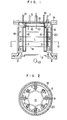
- Fig. 1 is a longitudinal cross-sectional view of a high frequency plasma generation apparatus, in which a plasma production chamber 1 is formed by sealing the upper end of the cylindrical side wall 20 with a back plate 19 and at the same time by sealing its lower end with a vessel not shown in the figure.
- a plasma production chamber 1 is formed by sealing the upper end of the cylindrical side wall 20 with a back plate 19 and at the same time by sealing its lower end with a vessel not shown in the figure.
- To the side wall 20 is fixed an extremity of each of insulating supporters 9, on the other extremity of which a high frequency coil 8 is mounted.
- the high frequency coil 8 is located at the neighborhood of the side wall 20 and feeded with high frequency electric power through a bushing 7 introduced hermetically and electrically insulated through the back plate 19.
- magnetic bodies 18 such as soft magnetic ferrite are mounted on the inner surface of the side wall 20 and also the two legs of insulating supporters 4 disposed inside of the high frequency coil 8 are fixed thereto.
- On the inner surface of these supporters 4 and of the back plate 19 are mounted permanent magnets and a magnetic field generation means 3 in order to produce a multi-cusp magnetic field.
- the soft magnetic ferrite 18 stated above forms a magnetic return path for the high frequency magnetic field produced by the high frequency coils 8.
- the high frequency coil 8 consists of a round tube cooled by water or oil flowing therethrough.
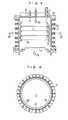
- the magnetic field production means 3 mentioned above is disposed in 8 rows in the plasma production chamber 1, as indicated in Fig. 2, which generates a multi-cusp magnetic field and forms a plasma confinement domain 12 indicated by a broken line in the figure.
- This plasma confinement domain 12 is located inside of the high frequency coil 8, which is protected against the plasma.
- the magnetic field production means 3 is located in a water or oil cooled case 16, which permits to avoid overheating due to plasma loss.
- the supply of this cooling medium is effected through a cooling medium introducing inlet 14 passing hermetically through the back plate 19.
- a gas inlet tube 6 and a starter filament 10 pass hermetically through the back plate 19. Reactive gas such as 0 2 is introduced through this gas inlet tube 6 and thermal electrons are emitted by heating the starter filament 10.
- the produced plasma has a tendency to diffuse towards the wall surface of the plasma production chamber 1, but it is confined within the domain 12 indicated in Fig. 2 by a multi-cusp magnetic field generated by a magnetic field production means 3.
- An ion beam 13 can be extracted from the plasma by applying a predetermined voltage to an electrodes 2 disposed in the bottom portion of the plasma production chamber 1.
- the high frequency coil 8 is disposed outside of the plasma confinement domain 12 by means of the magnetic field production means 3, that is, since the high frequency coil is separated from the plasma confinement domain by the magnetic field, electrical breakdown on the surface of the high frequency coil due to the plasma is prevented without providing electrical insulation coating thereon. Consequently the apparatus can work stably for a long time.
- the apparatus described in this embodiment By using the apparatus described in this embodiment, plasma of 0 2 gas was produced and an ion density of 0.8 - 1.0 x 10 (cm -3 ) in the plasma was obtained. Further a beam of 0 2 ions of 500 eV was extracted from the plasma and an ion beam current density of 0.65 mA/cm 2 was obtained.
- the maintenance interval i.e. the period of time during which the apparatus can be used without maintenance, is 5 times as long as that for a prior art apparatus using a filament.
- the apparatus described in this embodiment can work stably for a long time, even if reactive gas is used in order to extract a large amount of ion beam, while preventing electrical breakdown on the surface of the high frequency coil 8.
- the plasma is confined in a determined plasma confinement domain 12 by the multi-cusp magnetic field, an almost uniform plasma can be obtained in spite of a large plasma confinement domain 12 and it is easy to enlarge the diameter of the beam. That is, enlargement of the diameter of the beam can be realized by increasing the number of the magnetic field production means 3 or making it stronger so as to obtain an intensity of the magnetic field, which is sufficient to confine the plasma.
- Fig. 3 illustrates another embodiment of the high frequency plasma production apparatus of this invention.
- the magnetic field production means 3 for generating a multi-cusp magnetic field is disposed outside of the vessel forming the plasma production chamber 1. Further the magnetic field production means 3 have N poles and S poles disposed alternately along the axial direction on the side wall 20 and at the same time the poles of same polarity are arranged almost continuously in the circumferential direction on the side wall, as indicated in Fig. 4.
- the magnetic field production means 3 are arranged in a ring shape consisting of 7 layers with a predetermined interval in the axial direction on the side wall 20, and the high frequency coil 8 is so disposed that each turn is located between two adjacent layers at the neighborhood of the side wall 20 of the plasma production chamber 1 and fixed to the side wall 20 by an insulating supporter 21.
- the other constructions are identical to those described for the preceding embodiment.
- the identical or equivalent items are designated by same reference numerals and explanation more in detail therefor will be omitted.
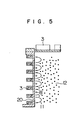
- Fig. 5 shows schematically the situation of the plasma confinement in the high frequency plasma production apparatus having the construction according to this embodiment.
- the magnetic field production means 3 disposed on the outer surface of the side wall 20 generates a magnetic field in the direction indicated by an arrow 11. Consequently, although the plasma generated by high frequency discharge has a tendency to diffuse towards the side wall 20, the diffusion is prevented by the magnetic field mentioned above and ions are confined in the domain 12 indicated by black points in the figure. In this way, electrical breakdown due to the plasma produced by the high frequency coil 8 can be prevented. Therefore, the same effects as those obtained in the preceding embodiment can be obtained also in this embodiment.
- the magnetic field production means 3 may be either an electromagnet or an permanent magnet, as stated previously, or still further their combination.
- a permanent magnet it is desirable to use a magnet fabricated by moulding magnetic powder with resin, because heat production by the high frequency magnetic field is reduced in this way.
- the apparatus can be used as an etching apparatus or a sputtering apparatus, when the ion beam extraction electrode 2 is removed from the construction indicated in the embodiments stated above and material to be worked is brought directly into contact with the plasma or reactive radicals, and thus it can be widely utilized as a high frequency plasma generation apparatus.
- nonreactive gas can be also used.
- the high frequency plasma generation apparatus since the plasma production chamber is formed by sealing hermetically the two extremities of its cylindrical side wall; a high frequency coil is disposed in the high frequency plasma generation chamber, which generates high frequency discharge by introducing gas for producing ions by discharge and at the same time by feeding it with high frequency electric power; and a magnetic field generation means producing a multi-cusp magnetic field for confining a plasma in the plasma production chamber is disposed at the neighborhood of the cylindrical side wall, the plasma is separated from the high frequency coil; electrical breakdown on the surface of the high frequency coil due to the plasma is prevented and thus it is possible to obtain a high frequency plasma generation apparatus, which can work stably for a long time.
Landscapes
- Physics & Mathematics (AREA)
- Engineering & Computer Science (AREA)
- Plasma & Fusion (AREA)
- Chemical & Material Sciences (AREA)
- Analytical Chemistry (AREA)
- Optics & Photonics (AREA)
- Spectroscopy & Molecular Physics (AREA)
- Drying Of Semiconductors (AREA)
- Plasma Technology (AREA)
- Electron Sources, Ion Sources (AREA)
Applications Claiming Priority (2)
| Application Number | Priority Date | Filing Date | Title |
|---|---|---|---|
| JP259884/84 | 1984-12-11 | ||
| JP59259884A JPH0740468B2 (ja) | 1984-12-11 | 1984-12-11 | 高周波プラズマ発生装置 |
Publications (3)
| Publication Number | Publication Date |
|---|---|
| EP0184812A2 true EP0184812A2 (fr) | 1986-06-18 |
| EP0184812A3 EP0184812A3 (en) | 1988-10-05 |
| EP0184812B1 EP0184812B1 (fr) | 1992-06-17 |
Family
ID=17340274
Family Applications (1)
| Application Number | Title | Priority Date | Filing Date |
|---|---|---|---|
| EP85115668A Expired - Lifetime EP0184812B1 (fr) | 1984-12-11 | 1985-12-09 | Générateur de plasma à haute fréquence |
Country Status (3)
| Country | Link |
|---|---|
| US (1) | US4716491A (fr) |
| EP (1) | EP0184812B1 (fr) |
| JP (1) | JPH0740468B2 (fr) |
Cited By (10)
| Publication number | Priority date | Publication date | Assignee | Title |
|---|---|---|---|---|
| US4713585A (en) * | 1985-09-30 | 1987-12-15 | Hitachi, Ltd. | Ion source |
| US4727293A (en) * | 1984-08-16 | 1988-02-23 | Board Of Trustees Operating Michigan State University | Plasma generating apparatus using magnets and method |
| EP0379828A2 (fr) * | 1989-01-25 | 1990-08-01 | International Business Machines Corporation | Dispositif de traitement par plasma multipolaire à induction de radiofréquence |
| GB2231197A (en) * | 1989-03-06 | 1990-11-07 | Nordiko Ltd | Plasma apparatus electrode assembly |
| GB2265635A (en) * | 1992-03-31 | 1993-10-06 | Commissariat Energie Atomique | Cathodic sputtering device comprising at least four targets using plasma produced by microwaves |
| US5280154A (en) * | 1992-01-30 | 1994-01-18 | International Business Machines Corporation | Radio frequency induction plasma processing system utilizing a uniform field coil |
| US5304279A (en) * | 1990-08-10 | 1994-04-19 | International Business Machines Corporation | Radio frequency induction/multipole plasma processing tool |
| EP0648069A1 (fr) * | 1993-07-30 | 1995-04-12 | Texas Instruments Incorporated | Source de plasma à induction RF pour traitements au plasma |
| WO2000062329A1 (fr) * | 1999-04-14 | 2000-10-19 | Tokyo Electron Limited | Procede et appareil permettant d'isoler une radio frequence de lignes d'alimentation et de decharge de milieu liquide de transfert thermique |
| GB2437804A (en) * | 2006-03-08 | 2007-11-07 | Alan Archibald Smith | Plasma confinement |
Families Citing this family (75)
| Publication number | Priority date | Publication date | Assignee | Title |
|---|---|---|---|---|
| JPH0711072B2 (ja) * | 1986-04-04 | 1995-02-08 | 株式会社日立製作所 | イオン源装置 |
| US4767931A (en) * | 1986-12-17 | 1988-08-30 | Hitachi, Ltd. | Ion beam apparatus |
| DE3708716C2 (de) * | 1987-03-18 | 1993-11-04 | Hans Prof Dr Rer Nat Oechsner | Hochfrequenz-ionenquelle |
| JPS63299338A (ja) * | 1987-05-29 | 1988-12-06 | Matsushita Electric Ind Co Ltd | プラズマ処理装置 |
| JP2656259B2 (ja) * | 1987-08-24 | 1997-09-24 | 日本原子力研究所 | イオン発生装置 |
| US4910436A (en) * | 1988-02-12 | 1990-03-20 | Applied Electron Corporation | Wide area VUV lamp with grids and purging jets |
| JP2618001B2 (ja) * | 1988-07-13 | 1997-06-11 | 三菱電機株式会社 | プラズマ反応装置 |
| GB8905073D0 (en) * | 1989-03-06 | 1989-04-19 | Nordiko Ltd | Ion gun |
| JP2568006B2 (ja) * | 1990-08-23 | 1996-12-25 | インターナショナル・ビジネス・マシーンズ・コーポレイション | イオン化空気により対象物から電荷を放電させる方法及びそのための装置 |
| US5208512A (en) * | 1990-10-16 | 1993-05-04 | International Business Machines Corporation | Scanned electron cyclotron resonance plasma source |
| FR2671931A1 (fr) * | 1991-01-22 | 1992-07-24 | Metal Process | Dispositif de repartition d'une energie micro-onde pour l'excitation d'un plasma. |
| US5189446A (en) * | 1991-05-17 | 1993-02-23 | International Business Machines Corporation | Plasma wafer processing tool having closed electron cyclotron resonance |
| US5308461A (en) * | 1992-01-14 | 1994-05-03 | Honeywell Inc. | Method to deposit multilayer films |
| US5216330A (en) * | 1992-01-14 | 1993-06-01 | Honeywell Inc. | Ion beam gun |
| US5962923A (en) * | 1995-08-07 | 1999-10-05 | Applied Materials, Inc. | Semiconductor device having a low thermal budget metal filling and planarization of contacts, vias and trenches |
| US6238533B1 (en) * | 1995-08-07 | 2001-05-29 | Applied Materials, Inc. | Integrated PVD system for aluminum hole filling using ionized metal adhesion layer |
| US6264812B1 (en) | 1995-11-15 | 2001-07-24 | Applied Materials, Inc. | Method and apparatus for generating a plasma |
| US5767628A (en) * | 1995-12-20 | 1998-06-16 | International Business Machines Corporation | Helicon plasma processing tool utilizing a ferromagnetic induction coil with an internal cooling channel |
| US6471822B1 (en) | 1996-01-24 | 2002-10-29 | Applied Materials, Inc. | Magnetically enhanced inductively coupled plasma reactor with magnetically confined plasma |
| KR100489918B1 (ko) * | 1996-05-09 | 2005-08-04 | 어플라이드 머티어리얼스, 인코포레이티드 | 플라즈마발생및스퍼터링용코일 |
| US6368469B1 (en) * | 1996-05-09 | 2002-04-09 | Applied Materials, Inc. | Coils for generating a plasma and for sputtering |
| US6254746B1 (en) | 1996-05-09 | 2001-07-03 | Applied Materials, Inc. | Recessed coil for generating a plasma |
| US6190513B1 (en) | 1997-05-14 | 2001-02-20 | Applied Materials, Inc. | Darkspace shield for improved RF transmission in inductively coupled plasma sources for sputter deposition |
| US6254737B1 (en) | 1996-10-08 | 2001-07-03 | Applied Materials, Inc. | Active shield for generating a plasma for sputtering |
| US6514390B1 (en) * | 1996-10-17 | 2003-02-04 | Applied Materials, Inc. | Method to eliminate coil sputtering in an ICP source |
| US5961793A (en) * | 1996-10-31 | 1999-10-05 | Applied Materials, Inc. | Method of reducing generation of particulate matter in a sputtering chamber |
| TW358964B (en) * | 1996-11-21 | 1999-05-21 | Applied Materials Inc | Method and apparatus for improving sidewall coverage during sputtering in a chamber having an inductively coupled plasma |
| US6599399B2 (en) | 1997-03-07 | 2003-07-29 | Applied Materials, Inc. | Sputtering method to generate ionized metal plasma using electron beams and magnetic field |
| US6103070A (en) * | 1997-05-14 | 2000-08-15 | Applied Materials, Inc. | Powered shield source for high density plasma |
| US6210539B1 (en) | 1997-05-14 | 2001-04-03 | Applied Materials, Inc. | Method and apparatus for producing a uniform density plasma above a substrate |
| US6652717B1 (en) | 1997-05-16 | 2003-11-25 | Applied Materials, Inc. | Use of variable impedance to control coil sputter distribution |
| US6579426B1 (en) | 1997-05-16 | 2003-06-17 | Applied Materials, Inc. | Use of variable impedance to control coil sputter distribution |
| US6077402A (en) * | 1997-05-16 | 2000-06-20 | Applied Materials, Inc. | Central coil design for ionized metal plasma deposition |
| US6361661B2 (en) | 1997-05-16 | 2002-03-26 | Applies Materials, Inc. | Hybrid coil design for ionized deposition |
| US6235169B1 (en) | 1997-08-07 | 2001-05-22 | Applied Materials, Inc. | Modulated power for ionized metal plasma deposition |
| US6345588B1 (en) | 1997-08-07 | 2002-02-12 | Applied Materials, Inc. | Use of variable RF generator to control coil voltage distribution |
| US6375810B2 (en) | 1997-08-07 | 2002-04-23 | Applied Materials, Inc. | Plasma vapor deposition with coil sputtering |
| US6565717B1 (en) | 1997-09-15 | 2003-05-20 | Applied Materials, Inc. | Apparatus for sputtering ionized material in a medium to high density plasma |
| US6042700A (en) * | 1997-09-15 | 2000-03-28 | Applied Materials, Inc. | Adjustment of deposition uniformity in an inductively coupled plasma source |
| US6023038A (en) * | 1997-09-16 | 2000-02-08 | Applied Materials, Inc. | Resistive heating of powered coil to reduce transient heating/start up effects multiple loadlock system |
| WO1999027579A1 (fr) * | 1997-11-26 | 1999-06-03 | Applied Materials, Inc. | Depot de revetement sculpte sans deterioration |
| US7253109B2 (en) | 1997-11-26 | 2007-08-07 | Applied Materials, Inc. | Method of depositing a tantalum nitride/tantalum diffusion barrier layer system |
| US6280579B1 (en) | 1997-12-19 | 2001-08-28 | Applied Materials, Inc. | Target misalignment detector |
| US6189484B1 (en) | 1999-03-05 | 2001-02-20 | Applied Materials Inc. | Plasma reactor having a helicon wave high density plasma source |
| US6254738B1 (en) | 1998-03-31 | 2001-07-03 | Applied Materials, Inc. | Use of variable impedance having rotating core to control coil sputter distribution |
| TW434636B (en) | 1998-07-13 | 2001-05-16 | Applied Komatsu Technology Inc | RF matching network with distributed outputs |
| US6132566A (en) * | 1998-07-30 | 2000-10-17 | Applied Materials, Inc. | Apparatus and method for sputtering ionized material in a plasma |
| US6579421B1 (en) | 1999-01-07 | 2003-06-17 | Applied Materials, Inc. | Transverse magnetic field for ionized sputter deposition |
| CA2401220C (fr) * | 2000-02-24 | 2009-05-19 | Ccr Gmbh Beschichtungstechnologie | Source de faisceaux plasma a haute frequence |
| US7513971B2 (en) * | 2002-03-18 | 2009-04-07 | Applied Materials, Inc. | Flat style coil for improved precision etch uniformity |
| JP2004031603A (ja) * | 2002-06-25 | 2004-01-29 | Nec Corp | レーザcvd装置、レーザcvd法、パターン欠陥修正装置及びパターン欠陥修正方法 |
| US7695590B2 (en) | 2004-03-26 | 2010-04-13 | Applied Materials, Inc. | Chemical vapor deposition plasma reactor having plural ion shower grids |
| US7291360B2 (en) | 2004-03-26 | 2007-11-06 | Applied Materials, Inc. | Chemical vapor deposition plasma process using plural ion shower grids |
| US7244474B2 (en) | 2004-03-26 | 2007-07-17 | Applied Materials, Inc. | Chemical vapor deposition plasma process using an ion shower grid |
| US7767561B2 (en) | 2004-07-20 | 2010-08-03 | Applied Materials, Inc. | Plasma immersion ion implantation reactor having an ion shower grid |
| US8058156B2 (en) | 2004-07-20 | 2011-11-15 | Applied Materials, Inc. | Plasma immersion ion implantation reactor having multiple ion shower grids |
| US7700925B2 (en) * | 2007-12-28 | 2010-04-20 | Varian Semiconductor Equipment Associates, Inc. | Techniques for providing a multimode ion source |
| ES2452519T3 (es) | 2009-05-13 | 2014-04-01 | Sio2 Medical Products, Inc. | Soporte de recipientes |
| US9458536B2 (en) | 2009-07-02 | 2016-10-04 | Sio2 Medical Products, Inc. | PECVD coating methods for capped syringes, cartridges and other articles |
| US11624115B2 (en) | 2010-05-12 | 2023-04-11 | Sio2 Medical Products, Inc. | Syringe with PECVD lubrication |
| US9878101B2 (en) | 2010-11-12 | 2018-01-30 | Sio2 Medical Products, Inc. | Cyclic olefin polymer vessels and vessel coating methods |
| US9272095B2 (en) | 2011-04-01 | 2016-03-01 | Sio2 Medical Products, Inc. | Vessels, contact surfaces, and coating and inspection apparatus and methods |
| US11116695B2 (en) | 2011-11-11 | 2021-09-14 | Sio2 Medical Products, Inc. | Blood sample collection tube |
| JP6095678B2 (ja) | 2011-11-11 | 2017-03-15 | エスアイオーツー・メディカル・プロダクツ・インコーポレイテッド | 薬剤パッケージ用の不動態化、pH保護又は滑性皮膜、被覆プロセス及び装置 |
| EP2846755A1 (fr) | 2012-05-09 | 2015-03-18 | SiO2 Medical Products, Inc. | Enrobage protecteur en saccharide pour conditionnement pharmaceutique |
| WO2014071061A1 (fr) | 2012-11-01 | 2014-05-08 | Sio2 Medical Products, Inc. | Procédés d'inspection de revêtement |
| US9903782B2 (en) | 2012-11-16 | 2018-02-27 | Sio2 Medical Products, Inc. | Method and apparatus for detecting rapid barrier coating integrity characteristics |
| US9764093B2 (en) | 2012-11-30 | 2017-09-19 | Sio2 Medical Products, Inc. | Controlling the uniformity of PECVD deposition |
| BR112015012470B1 (pt) | 2012-11-30 | 2022-08-02 | Sio2 Medical Products, Inc | Método de produção de um tambor médico para um cartucho ou seringa médica |
| WO2014134577A1 (fr) | 2013-03-01 | 2014-09-04 | Sio2 Medical Products, Inc. | Prétraitement par plasma ou par dépôt chimique en phase vapeur pour kit pharmaceutique lubrifié, procédé de revêtement et appareil |
| US9937099B2 (en) | 2013-03-11 | 2018-04-10 | Sio2 Medical Products, Inc. | Trilayer coated pharmaceutical packaging with low oxygen transmission rate |
| CN110074968B (zh) | 2013-03-11 | 2021-12-21 | Sio2医药产品公司 | 涂布包装材料 |
| US20160017490A1 (en) | 2013-03-15 | 2016-01-21 | Sio2 Medical Products, Inc. | Coating method |
| WO2015148471A1 (fr) | 2014-03-28 | 2015-10-01 | Sio2 Medical Products, Inc. | Revêtements antistatiques pour des récipients en plastique |
| US11077233B2 (en) | 2015-08-18 | 2021-08-03 | Sio2 Medical Products, Inc. | Pharmaceutical and other packaging with low oxygen transmission rate |
Citations (1)
| Publication number | Priority date | Publication date | Assignee | Title |
|---|---|---|---|---|
| US3774001A (en) * | 1971-11-22 | 1973-11-20 | Commissariat Energie Atomique | Chamber for the high-frequency heating of a conducting medium |
Family Cites Families (8)
| Publication number | Priority date | Publication date | Assignee | Title |
|---|---|---|---|---|
| US3230418A (en) * | 1961-06-23 | 1966-01-18 | Raphael A Dandl | Device having high-gradient magnetic cusp geometry |
| US3467885A (en) * | 1965-05-20 | 1969-09-16 | Xerox Corp | Method and apparatus for electromagnetically containing a plasma |
| US3527977A (en) * | 1968-06-03 | 1970-09-08 | Atomic Energy Commission | Moving electrons as an aid to initiating reactions in thermonuclear devices |
| US4233109A (en) * | 1976-01-16 | 1980-11-11 | Zaidan Hojin Handotai Kenkyu Shinkokai | Dry etching method |
| US4152625A (en) * | 1978-05-08 | 1979-05-01 | The United States Of America As Represented By The Secretary Of The Army | Plasma generation and confinement with continuous wave lasers |
| US4351712A (en) * | 1980-12-10 | 1982-09-28 | International Business Machines Corporation | Low energy ion beam oxidation process |
| JPS58154554U (ja) * | 1982-04-09 | 1983-10-15 | 日本電子株式会社 | 高周波イオン源 |
| JPH0693447B2 (ja) * | 1983-12-23 | 1994-11-16 | 株式会社日立製作所 | マイクロ波プラズマ処理装置 |
-
1984
- 1984-12-11 JP JP59259884A patent/JPH0740468B2/ja not_active Expired - Lifetime
-
1985
- 1985-12-09 US US06/806,341 patent/US4716491A/en not_active Expired - Fee Related
- 1985-12-09 EP EP85115668A patent/EP0184812B1/fr not_active Expired - Lifetime
Patent Citations (1)
| Publication number | Priority date | Publication date | Assignee | Title |
|---|---|---|---|---|
| US3774001A (en) * | 1971-11-22 | 1973-11-20 | Commissariat Energie Atomique | Chamber for the high-frequency heating of a conducting medium |
Non-Patent Citations (3)
| Title |
|---|
| IEEE TRANSACTIONS ON NUCLEAR SCIENCE, vol. NS-28, no. 3, part 1, June 1981, pages 2666-2668, IEEE, New York, US; T.C. CHRISTENSEN et al.: "Performance of intense pulsed ion source" * |
| REVIEW OF SCIENTIFIC INSTRUMENTS, vol. 55, no. 3, March 1984, pages 342-346, American Institute of Physics, New York, US; K.N. LEUNG et al.: "Ion source operation with different magnetic confinement geometries" * |
| REVUE DE PHYSIQUE APPLIQUEE, vol. 12, no. 8, August 1977, pages 1143-1148, Paris, FR; A. TRUC et al.: "Parodie, plasma stationnaire homogène de grande dimension" * |
Cited By (15)
| Publication number | Priority date | Publication date | Assignee | Title |
|---|---|---|---|---|
| US4727293A (en) * | 1984-08-16 | 1988-02-23 | Board Of Trustees Operating Michigan State University | Plasma generating apparatus using magnets and method |
| US4713585A (en) * | 1985-09-30 | 1987-12-15 | Hitachi, Ltd. | Ion source |
| EP0379828A2 (fr) * | 1989-01-25 | 1990-08-01 | International Business Machines Corporation | Dispositif de traitement par plasma multipolaire à induction de radiofréquence |
| EP0379828A3 (fr) * | 1989-01-25 | 1991-01-09 | International Business Machines Corporation | Dispositif de traitement par plasma multipolaire à induction de radiofréquence |
| GB2231197B (en) * | 1989-03-06 | 1994-03-30 | Nordiko Ltd | Electrode assembly and apparatus |
| GB2231197A (en) * | 1989-03-06 | 1990-11-07 | Nordiko Ltd | Plasma apparatus electrode assembly |
| US5304279A (en) * | 1990-08-10 | 1994-04-19 | International Business Machines Corporation | Radio frequency induction/multipole plasma processing tool |
| US5280154A (en) * | 1992-01-30 | 1994-01-18 | International Business Machines Corporation | Radio frequency induction plasma processing system utilizing a uniform field coil |
| GB2265635A (en) * | 1992-03-31 | 1993-10-06 | Commissariat Energie Atomique | Cathodic sputtering device comprising at least four targets using plasma produced by microwaves |
| GB2265635B (en) * | 1992-03-31 | 1995-06-28 | Commissariat Energie Atomique | Cathodic sputtering device using a plasma produced by microwaves |
| EP0648069A1 (fr) * | 1993-07-30 | 1995-04-12 | Texas Instruments Incorporated | Source de plasma à induction RF pour traitements au plasma |
| US5430355A (en) * | 1993-07-30 | 1995-07-04 | Texas Instruments Incorporated | RF induction plasma source for plasma processing |
| WO2000062329A1 (fr) * | 1999-04-14 | 2000-10-19 | Tokyo Electron Limited | Procede et appareil permettant d'isoler une radio frequence de lignes d'alimentation et de decharge de milieu liquide de transfert thermique |
| US6284110B1 (en) | 1999-04-14 | 2001-09-04 | Tokyo Electron Limited | Method and apparatus for radio frequency isolation of liquid heat transfer medium supply and discharge lines |
| GB2437804A (en) * | 2006-03-08 | 2007-11-07 | Alan Archibald Smith | Plasma confinement |
Also Published As
| Publication number | Publication date |
|---|---|
| US4716491A (en) | 1987-12-29 |
| EP0184812B1 (fr) | 1992-06-17 |
| JPH0740468B2 (ja) | 1995-05-01 |
| EP0184812A3 (en) | 1988-10-05 |
| JPS61138432A (ja) | 1986-06-25 |
Similar Documents
| Publication | Publication Date | Title |
|---|---|---|
| US4716491A (en) | High frequency plasma generation apparatus | |
| US7176469B2 (en) | Negative ion source with external RF antenna | |
| US5763989A (en) | Closed drift ion source with improved magnetic field | |
| JP2648235B2 (ja) | イオン銃 | |
| KR910010099B1 (ko) | Ecr 이온 소스 | |
| TWI467615B (zh) | 離子源與調整離子束均一性的方法 | |
| US4122347A (en) | Ion source | |
| JPS63276858A (ja) | イオンビーム発生装置 | |
| EP0740327B1 (fr) | Appareil de traitement par faisceau d'ions | |
| US6975072B2 (en) | Ion source with external RF antenna | |
| EP0249658B1 (fr) | Source d'ions | |
| JP3481953B2 (ja) | 基板をコーティングするための装置 | |
| Torii et al. | A high‐current density and long lifetime ECR source for oxygen implanters | |
| JPH0746588B2 (ja) | マイクロ波イオン源 | |
| Ivanov Jr et al. | H− ion production in electron cyclotron resonance driven multicusp volume source | |
| JPS6293834A (ja) | イオン源 | |
| Fukumasa et al. | Electron cyclotron resonance negative ion source | |
| Hakamata et al. | Bucket type ion source using a microwave plasma cathode | |
| JPS5740845A (en) | Ion beam generator | |
| JPH09259781A (ja) | イオン源装置 | |
| JP2614632B2 (ja) | 負イオン発生装置 | |
| JP3010978B2 (ja) | イオン源装置 | |
| TW201824366A (zh) | 離子植入機以及將離子植入半導體基板中的方法 | |
| Hashimoto et al. | Extraction of a negative hydrogen ion beam from a microwave ion source | |
| Bacal et al. | ECR‐Driven Multicusp Volume H− Ion Source |
Legal Events
| Date | Code | Title | Description |
|---|---|---|---|
| PUAI | Public reference made under article 153(3) epc to a published international application that has entered the european phase |
Free format text: ORIGINAL CODE: 0009012 |
|
| AK | Designated contracting states |
Kind code of ref document: A2 Designated state(s): CH DE FR GB IT LI NL SE |
|
| PUAL | Search report despatched |
Free format text: ORIGINAL CODE: 0009013 |
|
| AK | Designated contracting states |
Kind code of ref document: A3 Designated state(s): CH DE FR GB IT LI NL SE |
|
| 17P | Request for examination filed |
Effective date: 19881006 |
|
| 17Q | First examination report despatched |
Effective date: 19881201 |
|
| GRAA | (expected) grant |
Free format text: ORIGINAL CODE: 0009210 |
|
| AK | Designated contracting states |
Kind code of ref document: B1 Designated state(s): DE FR GB |
|
| REF | Corresponds to: |
Ref document number: 3586239 Country of ref document: DE Date of ref document: 19920723 |
|
| ET | Fr: translation filed | ||
| PLBE | No opposition filed within time limit |
Free format text: ORIGINAL CODE: 0009261 |
|
| STAA | Information on the status of an ep patent application or granted ep patent |
Free format text: STATUS: NO OPPOSITION FILED WITHIN TIME LIMIT |
|
| 26N | No opposition filed | ||
| PGFP | Annual fee paid to national office [announced via postgrant information from national office to epo] |
Ref country code: FR Payment date: 19931029 Year of fee payment: 9 |
|
| PGFP | Annual fee paid to national office [announced via postgrant information from national office to epo] |
Ref country code: GB Payment date: 19931129 Year of fee payment: 9 |
|
| PGFP | Annual fee paid to national office [announced via postgrant information from national office to epo] |
Ref country code: DE Payment date: 19940228 Year of fee payment: 9 |
|
| PG25 | Lapsed in a contracting state [announced via postgrant information from national office to epo] |
Ref country code: GB Effective date: 19941209 |
|
| GBPC | Gb: european patent ceased through non-payment of renewal fee |
Effective date: 19941209 |
|
| PG25 | Lapsed in a contracting state [announced via postgrant information from national office to epo] |
Ref country code: FR Effective date: 19950831 |
|
| PG25 | Lapsed in a contracting state [announced via postgrant information from national office to epo] |
Ref country code: DE Effective date: 19950901 |
|
| REG | Reference to a national code |
Ref country code: FR Ref legal event code: ST |