EP0183554B1 - Video/compact disk player - Google Patents
Video/compact disk player Download PDFInfo
- Publication number
- EP0183554B1 EP0183554B1 EP85308680A EP85308680A EP0183554B1 EP 0183554 B1 EP0183554 B1 EP 0183554B1 EP 85308680 A EP85308680 A EP 85308680A EP 85308680 A EP85308680 A EP 85308680A EP 0183554 B1 EP0183554 B1 EP 0183554B1
- Authority
- EP
- European Patent Office
- Prior art keywords
- disk
- pickup
- start position
- player system
- instructing
- Prior art date
- Legal status (The legal status is an assumption and is not a legal conclusion. Google has not performed a legal analysis and makes no representation as to the accuracy of the status listed.)
- Expired
Links
Images


Classifications
-
- G—PHYSICS
- G11—INFORMATION STORAGE
- G11B—INFORMATION STORAGE BASED ON RELATIVE MOVEMENT BETWEEN RECORD CARRIER AND TRANSDUCER
- G11B19/00—Driving, starting, stopping record carriers not specifically of filamentary or web form, or of supports therefor; Control thereof; Control of operating function ; Driving both disc and head
- G11B19/20—Driving; Starting; Stopping; Control thereof
-
- G—PHYSICS
- G11—INFORMATION STORAGE
- G11B—INFORMATION STORAGE BASED ON RELATIVE MOVEMENT BETWEEN RECORD CARRIER AND TRANSDUCER
- G11B21/00—Head arrangements not specific to the method of recording or reproducing
- G11B21/02—Driving or moving of heads
- G11B21/08—Track changing or selecting during transducing operation
- G11B21/081—Access to indexed tracks or parts of continuous track
- G11B21/083—Access to indexed tracks or parts of continuous track on discs
-
- G—PHYSICS
- G11—INFORMATION STORAGE
- G11B—INFORMATION STORAGE BASED ON RELATIVE MOVEMENT BETWEEN RECORD CARRIER AND TRANSDUCER
- G11B7/00—Recording or reproducing by optical means, e.g. recording using a thermal beam of optical radiation by modifying optical properties or the physical structure, reproducing using an optical beam at lower power by sensing optical properties; Record carriers therefor
- G11B7/08—Disposition or mounting of heads or light sources relatively to record carriers
- G11B7/085—Disposition or mounting of heads or light sources relatively to record carriers with provision for moving the light beam into, or out of, its operative position or across tracks, otherwise than during the transducing operation, e.g. for adjustment or preliminary positioning or track change or selection
- G11B7/08505—Methods for track change, selection or preliminary positioning by moving the head
Definitions
- the present invention relates to a player for video or compact disks. More specifically, the invention relates to such a player having an improved function of starting the playing of a disk, particularly, a CLV (Constant Linear Velocity) type disk played at a non-constant angular velocity at other that its ordinary beginning position.
- a CLV Constant Linear Velocity
- a control code is read from the program area of the disk to determine whether the disk is recorded in the CLV mode or the CAV (Constant Angular Velocity) mode. Subsequently, the start address of the desired selection is searched for. When this start address is reached, play of the disk is commenced in the specified mode.
- the desired playback start position is specified in the form of chapter, frame and time numbers.
- a microprocessor contained in the control unit for the player instructs the carrying out of the search operation using this data. In doing so, the pickup is moved in the radial direction of the disk from the innermost or outermost edge of the area where information is recorded to the indicated start position, reading out chapter numbers as it is moving.
- the spindle servo which controls the rotational speed of the disk
- the disk is rotated at the appropriate speed for the location of the pickup.
- start and then search movements must be performed sequentially. As a result, much time passes before the playing of the desired selection can begin. In a player in which the parked position of the pickup is at the inner periphery of the disk, as much as 30 seconds may pass before a desired selection can be played, about 15 seconds for the start operations and about another 15 seconds for the search operation in the case of a 30 cm CLV disk.
- EP-A-0123946 discloses a compact disk player which operates in the conventional manner described above.
- the invention provides a disk player system comprising pickup means for reading information recorded on a disk being played, said disk having program information stored at either its inner or outermost edge and recorded information; means for moving the pickup means radially of the disk; means for instructing the pickup moving means to move the pickup means to a first start position before commencing a search operation to move the pickup means to a second start position, the second start position being a start position of a designated program recorded on the disk; and, means for rotating the disk when the pickup means is at the first start position at a speed suitable for reading information from the disk by the pickup means at the first start position; characterised in that:
- the first start position is preferably substantially at a middle position, in the radial direction of the disk, of the area containing recorded information.
- the instructing means may comprise means for supplying an instructing voltage to the pickup moving means for moving the pickup means in response to the voltage.
- the first start position may be set to correspond to a playback start position.
- the instucting means may comprise means for supplying an instructing digital signal to the pickup moving means for moving the pickup means to the start position, and the instructing means may comprise a digital-to-analog converter.
- the rotating means may include means for establishing a speed of rotation of the disk in response to the digital signal. Also, the rotating means may set the speed of rotation of the disk in response to an output of the digital-to-analog converter.
- the disk player system may further comprise means for detecting a radial position of the pickup means relative to the disk, and the rotating means may establish the speed of rotation of the disk in response to an output of the detecting means representative of the radial position.
- the invention is especially advantageous for use with a CLV type disk.
- Figure 1 is shown a block diagram of a video disk player constructed in accordance with a first preferred embodiments of the invention.
- a disk 1 is rotated by a spindle motor 3 having associated therewith a tachometer 2 which detects the speed of rotation of the motor 3.
- a pickup 4 reads the data recorded on the disk 1 as it rotates using a laser beam or the like reflected from the tracks on the surface of the disk 1.
- the output reproduced signal from the pickup 1 is amplified by a head amplifier 5, and the resulting RF or HF signal is supplied to a filter 6 which divides the signal into video and audio signal components, which in turn are supplied to an audio signal demodulator 7 and a video signal demodulator 8, respectively.
- a focus error signal also produced by the head amplifier 5 is supplied to a focus servo circuit 9 with which the focusing of the reading beam of the pickup is controlled.
- a tracking error signal produced by the head amplifier 5 is supplied to a tracking servo circuit 10 with which the position of the reading spot ofthe pickup 4 relative to the tracks on the disk 1 is controlled.
- a synchronizing signal separator 12 in a spindle servo circuit 11 is provided to separate colour burst and horizontal synchronizing signals from the output of the video signal demodulator 8, and the separated signals are supplied to a phase comparator 14 along with a reference signal, having a fixed frequency and phase, from a reference oscillator 13.
- the output of the phase comparator 14 is compensated and amplified by a compensating amplifier 15 before being supplied to a comparator 17 through a switch 16.
- the output of the tachometer 2 is supplied to the other input of the comparator 17, whose output is used to drive the spindle motor 3 through an amplifier 18.
- the control shaft of a potentiometer 19 is interlocked with the movement of the pickup 4, that is, the position of the resistance setting of the potentiometer 19 is varied in accordance with the radial position of the pickup 4 relative to the disk 1. Accordingly, a voltage signal is produced at the wiper contact of the potentiometer 19 representative of the radial position of the pickup 4 relative to the disk 1.
- This output of the potentiometer 19 is supplied to the comparator 17 through a comparator 20 and the switch 16.
- a variable resistor 21, used to set the start position of the pickup 4, provides a reference voltage to the comparator 20.
- This reference voltage may be a value which causes the pickup 4 to be positioned at other than the areas surrounding the innermost and outermost edges of the recorded area of the disk 1.
- the variable resistor 21 can be set so as to cause the pickup 4 to be positioned approximately at the middle of the recorded area on the disk 1.
- the output of the comparator 20 is supplied to a slider servo circuit 23 trough a switch 22 and is used to drive a slider motor 24 which moves the pickup 4 in the radial direction of the disk 1.
- a CPU (Central Processing Unit) 25, such as a microprocessor, is used to control the switches 16 and 22, as well as various other circuit elements.
- the CPU When the operator specifies an input search address (including time, chapter, frame number, etc.) and presses the PLAY button, the CPU will issue starting instructions to the various controlled circuit elements, specifically, setting the switches 16 and 22 to their downward positions as shown in Figures 1 and 2.
- the variable resistor 21 is assumed to be set so as to cause the pickup 4 to be moved to a first start position near the middle of the recorded information on the disk 1.
- the output of the potentiometer 19 is supplied to one input of the comparator 17 through the switch 16 and the output of the tachometer 2 to the other input of the comparator 17. Because the disk is not rotated substantially during this initial period, the output from the tachometer 24 is at a low level.
- the output from the comparator 17 is high, and hence the pickup 4 is transported to the starting position atthe middle of the recorded area on the disk 1, the spindle motor 3 being driven by the output of the power amplifier 18 in response to this high output from the comparator 17 while the disk 1 is being rotated.
- the rotational speed of the CLV disk 1 is smaller when the pickup 4 is near its outer periphery than when the pickup 4 is near its inner periphery. Consequently, the number of revolutions of the disk 1 until the pickup 4 reaches a starting position on the outer periphery of the recorded area on the disk 1 is significantly less than when the pickup 4 is moved to a starting position on the inner periphery of the recorded area. Thus, a shorter period of time is needed to move the pickup 4 to a starting position on the outer periphery of the disk 1.
- the CPU 25 sets the switches 16 and 22 to their upward positions shown in Figures 1 and 2, whereupon a normal servo lock-in operation is performed.
- the slider servo follows the tracking servo because the tracking servo circuit supplied the DC component of the tracking error signal to the slider servo circuit 23 through the switch 22. Since the spindle servo circuit 11 operates to make the frequency and phase of the output signal of the tachometer 2 follow the colour subcarrier separated out by the synchronizing signal separator 12, the disk 1 is rotated at the normal speed, whereupon audio and video output are provided by the respective audio and video signal demodulators 7 and 8. At this time, address data, etc., indicative of the present position of the pickup 4 is obtainable.
- the CPU then begins the search sequence. Specifically, because the pickup 4 is located substantially at the middle of the recorded area on the disk 1, which location is other than the expected normal starting point of the playing operation, it is necessary for the CPU to compute the difference between the specified and present positions and move the pickup 4 towards the specified position in accordance with the calculated difference. In the worst case, because the distance covered by the pickup 4 is only about half the track zone of the disk 1, the time required for searching purposes will be much shorter than in a conventional player on the average.
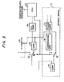
- FIG 2 shows a second embodiment of the invention, wherein like reference numbers designate like elements in Figure 1.
- the output of the variable resistor 21, rather than the output of the potentiometer 19, is used as the reference signal for the comparator 17 in the starting sequence.
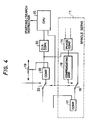
- a digital output of the CPU 25, instead of the output of the variable resistor 21, is supplied as the reference signal to the comparator 17, supplied through a digital-to-analog converter 30.
- the arrangements of Figures 3 and 4 are similar to those of Figures 1 and 2.
- the starting point of the pickup can be changed by the operator by entering a new starting point via the CPU 25 as control program data. Such an arrangement is particularly advantageous when the desired starting point on the disk 1 is known in advance.
- the correlation between the frame and time number to the corresponding reading position on the disk can be expressed in the form of a mathematical formula, which formula can be stored in advance in the program memory of the CPU 25 and used to compute the proper starting point of the pickup 4. Also, by performing the required comparisons digitally in the CPU, the digital-to-analog converter can be eliminated.
- the invention provides a disk player system in which the pickup is initially quickly transported to a start position substantially at the middle of the recorded area on the disk, that is, to a start position other than near the innermost or outermost edges of the recorded area. Accordingly, the number of revolutions of the disk needed before the pickup reaches the designated playing position is substantially reduced on the average.
Landscapes
- Indexing, Searching, Synchronizing, And The Amount Of Synchronization Travel Of Record Carriers (AREA)
- Moving Of Head For Track Selection And Changing (AREA)
Applications Claiming Priority (2)
| Application Number | Priority Date | Filing Date | Title |
|---|---|---|---|
| JP59251383A JPS61129778A (ja) | 1984-11-28 | 1984-11-28 | デイスク再生方式 |
| JP251383/84 | 1984-11-28 |
Publications (3)
| Publication Number | Publication Date |
|---|---|
| EP0183554A2 EP0183554A2 (en) | 1986-06-04 |
| EP0183554A3 EP0183554A3 (en) | 1987-06-24 |
| EP0183554B1 true EP0183554B1 (en) | 1991-01-30 |
Family
ID=17222015
Family Applications (1)
| Application Number | Title | Priority Date | Filing Date |
|---|---|---|---|
| EP85308680A Expired EP0183554B1 (en) | 1984-11-28 | 1985-11-28 | Video/compact disk player |
Country Status (4)
| Country | Link |
|---|---|
| US (1) | US4855978A (ja) |
| EP (1) | EP0183554B1 (ja) |
| JP (1) | JPS61129778A (ja) |
| DE (1) | DE3581603D1 (ja) |
Families Citing this family (31)
| Publication number | Priority date | Publication date | Assignee | Title |
|---|---|---|---|---|
| KR910003458B1 (ko) * | 1986-12-02 | 1991-05-31 | 미쓰비시뎅끼 가부시끼가이샤 | 광디스크의 구동장치 |
| JP2687340B2 (ja) * | 1987-03-20 | 1997-12-08 | 松下電器産業株式会社 | 光学式デイスク再生装置 |
| JPS63282958A (ja) * | 1987-05-15 | 1988-11-18 | Pioneer Electronic Corp | ディスク再生装置 |
| EP0391422B1 (en) * | 1989-04-06 | 1995-07-05 | Kabushiki Kaisha Toshiba | Optical disk unit |
| US5157645A (en) * | 1989-04-06 | 1992-10-20 | Kabushiki Kaisha Toshiba | Optical disk unit |
| US5268804A (en) * | 1989-04-26 | 1993-12-07 | International Business Machines Corporation | Actuator arm controller for a storage device |
| JPH0724142B2 (ja) * | 1989-04-28 | 1995-03-15 | 株式会社ケンウッド | 光ディスクのサーボ回路 |
| JP2578973B2 (ja) * | 1989-05-01 | 1997-02-05 | パイオニア株式会社 | オン/オフトラック検出機能を有するコンパチブルディスクプレーヤ |
| JPH0369062A (ja) * | 1989-08-07 | 1991-03-25 | Pioneer Electron Corp | 光ディスク記録再生装置のスピンドル制御装置 |
| US4988932A (en) * | 1989-10-10 | 1991-01-29 | Eastman Kodak Company | Constant velocity servosystem wtih high positional accuracy |
| KR920003426B1 (ko) * | 1989-10-13 | 1992-04-30 | 삼성전자 주식회사 | 스핀들 모터의 과회전 방지장치 |
| DE69118421T2 (de) * | 1990-02-01 | 1996-09-12 | Matsushita Electric Ind Co Ltd | Gerät zur Wiedergabe von Daten, um eine hohe Übertragungsgeschwindigkeit zu realisieren |
| JPH0778974B2 (ja) * | 1990-09-27 | 1995-08-23 | インターナシヨナル・ビジネス・マシーンズ・コーポレーシヨン | 光ディスク駆動装置の初期設定方法 |
| KR930003193B1 (ko) * | 1991-01-25 | 1993-04-23 | 삼성전자주식회사 | 스핀들 모터 이상 회전 방지회로 |
| DE4103975A1 (de) * | 1991-02-09 | 1992-08-13 | Thomson Brandt Gmbh | Verfahren zur verkuerzung der zugriffszeit |
| US5276569A (en) * | 1991-06-26 | 1994-01-04 | Digital Equipment Corporation | Spindle controller with startup correction of disk position |
| CA2073400A1 (en) * | 1991-11-08 | 1993-05-09 | Masayuki Hoshi | Disk player |
| JP2716902B2 (ja) * | 1992-02-14 | 1998-02-18 | 富士通株式会社 | 光ディスク装置 |
| JP3336629B2 (ja) * | 1992-06-09 | 2002-10-21 | ソニー株式会社 | 光ディスク装置および光ピックアップの移動方法 |
| JP3264994B2 (ja) * | 1992-09-22 | 2002-03-11 | パイオニア株式会社 | 記録媒体演奏装置 |
| US5438464A (en) * | 1993-04-23 | 1995-08-01 | Quantum Corporation | Synchronization of multiple disk drive spindles |
| US5448428A (en) * | 1993-04-23 | 1995-09-05 | Quantum Corporation | Phase locking a disk drive spindle to a reference signal |
| US5583841A (en) * | 1995-01-17 | 1996-12-10 | Discovision Associates | Apparatus for improved search on information storage member rotating at constant linear velocity |
| JP3056967B2 (ja) * | 1995-02-24 | 2000-06-26 | 株式会社朝日コーポレーション | ディスクプレーヤ |
| US5978329A (en) | 1995-06-07 | 1999-11-02 | Discovision Associates | Technique for closed loop servo operation in optical disc tracking control |
| US5815480A (en) * | 1995-09-05 | 1998-09-29 | Wea Manufacturing, Inc. | Method for calculating and recording a start program radius upon a compact disc |
| EP0777218B1 (en) | 1995-12-06 | 2001-05-16 | Discovision Associates | Apparatus and method for focus control |
| JP2837121B2 (ja) * | 1995-12-27 | 1998-12-14 | 三星電子株式会社 | スピンドルモーターの駆動装置 |
| US5689485A (en) | 1996-04-01 | 1997-11-18 | Discovision Associates | Tracking control apparatus and method |
| EP1069562A1 (en) * | 1999-07-13 | 2001-01-17 | Deutsche Thomson-Brandt Gmbh | Disc speed control device |
| CN101901612B (zh) * | 2009-05-27 | 2013-07-24 | 珠海扬智电子有限公司 | 变速不变调的声音播放方法及装置 |
Family Cites Families (14)
| Publication number | Priority date | Publication date | Assignee | Title |
|---|---|---|---|---|
| JPS5011246A (ja) * | 1973-05-30 | 1975-02-05 | ||
| US4223349A (en) * | 1978-11-16 | 1980-09-16 | Mca Discovision, Inc. | System for rotating an information storage disc at a variable angular velocity to recover information therefrom at a prescribed constant rate |
| US4228326A (en) * | 1978-11-16 | 1980-10-14 | Mca Discovision Inc. | System for recording information on a rotatable storage disc, in a substantially uniform recording density |
| GB2046979B (en) * | 1979-04-17 | 1983-05-18 | Burroughs Corp | Recording and replay apparatus employing rotary media |
| JPS5746355A (en) * | 1980-09-04 | 1982-03-16 | Matsushita Electric Ind Co Ltd | Speed controller of turntable |
| JPS5787371U (ja) * | 1980-11-17 | 1982-05-29 | ||
| JPS5823365A (ja) * | 1981-08-03 | 1983-02-12 | Nippon Telegr & Teleph Corp <Ntt> | 位置決め機構制御方式 |
| JPS5877068A (ja) * | 1981-10-31 | 1983-05-10 | Toshiba Corp | デイスク再生装置におけるサ−チ方式 |
| JPS5888874A (ja) * | 1981-11-20 | 1983-05-27 | Toshiba Corp | 情報記録再生装置 |
| JPS58200470A (ja) * | 1982-05-18 | 1983-11-22 | Matsushita Electric Ind Co Ltd | デイスク再生装置 |
| JPS5942670A (ja) * | 1982-09-01 | 1984-03-09 | Canon Inc | 画像情報記録再生装置 |
| JPS59185071A (ja) * | 1983-04-04 | 1984-10-20 | Hitachi Ltd | 情報記録デイスクの再生速度制御装置 |
| JPS59186178A (ja) * | 1983-04-08 | 1984-10-22 | Matsushita Electric Ind Co Ltd | Clvデイスクのランダムアクセス装置 |
| JPH0812743B2 (ja) * | 1983-06-30 | 1996-02-07 | 株式会社東芝 | ディスク装置 |
-
1984
- 1984-11-28 JP JP59251383A patent/JPS61129778A/ja active Pending
-
1985
- 1985-11-28 EP EP85308680A patent/EP0183554B1/en not_active Expired
- 1985-11-28 DE DE8585308680T patent/DE3581603D1/de not_active Expired - Fee Related
-
1987
- 1987-11-24 US US07/129,391 patent/US4855978A/en not_active Expired - Fee Related
Also Published As
| Publication number | Publication date |
|---|---|
| DE3581603D1 (de) | 1991-03-07 |
| EP0183554A2 (en) | 1986-06-04 |
| JPS61129778A (ja) | 1986-06-17 |
| US4855978A (en) | 1989-08-08 |
| EP0183554A3 (en) | 1987-06-24 |
Similar Documents
| Publication | Publication Date | Title |
|---|---|---|
| EP0183554B1 (en) | Video/compact disk player | |
| US5216647A (en) | Target track position retrieval device | |
| US5444687A (en) | Method and device for accessing an optical disc | |
| US5136560A (en) | CAV/CLV composite disk accessing method utilizing different accessing procedures for respective CAV and CLV areas | |
| US5161142A (en) | Disk playing apparatus for playing CLV disks | |
| JPS6146907B2 (ja) | ||
| US5063550A (en) | Loop-gain control system in a spindle servo loop | |
| US4841505A (en) | Pickup position control method enabling restart of reproduction after interruption | |
| JPH02173970A (ja) | ディスクプレーヤの回転制御方式 | |
| US4882719A (en) | Disk playing method for disk player | |
| US5321677A (en) | High-speed search apparatus for use with a video disk player | |
| US5047999A (en) | Optical record carrier reader calculating track pitch and write velocity for locating read point | |
| US5132946A (en) | Player apparatus for playing information on an information recording medium and having search function | |
| US4845572A (en) | Multiplied-speed reproducing system in information reproducing apparatus | |
| US4893294A (en) | Disk player and disk playing method in which tracking miss tolerance is adjusted | |
| US4835753A (en) | Information playback system having an address search operation using a variable speed pickup positioning system | |
| US5146347A (en) | Disc player control system for quickly placing disc player in command ready state | |
| JPH02263361A (ja) | ディスク演奏装置 | |
| US5173887A (en) | Disk player pickup control system | |
| JP2664605B2 (ja) | ディスクの線速度測定方法 | |
| JPS63127463A (ja) | デイスク再生装置におけるサ−チ方式 | |
| JPH0221426A (ja) | ビデオ・ディスク再生装置 | |
| KR960003704B1 (ko) | 디스크재생시스템의 고속기동장치와 그 방법 | |
| KR20010024928A (ko) | 디스크 장치 | |
| JP2902892B2 (ja) | ディスクプレーヤーのサーチ方法 |
Legal Events
| Date | Code | Title | Description |
|---|---|---|---|
| PUAI | Public reference made under article 153(3) epc to a published international application that has entered the european phase |
Free format text: ORIGINAL CODE: 0009012 |
|
| AK | Designated contracting states |
Kind code of ref document: A2 Designated state(s): DE FR GB NL |
|
| PUAL | Search report despatched |
Free format text: ORIGINAL CODE: 0009013 |
|
| RHK1 | Main classification (correction) |
Ipc: G11B 19/20 |
|
| AK | Designated contracting states |
Kind code of ref document: A3 Designated state(s): DE FR GB NL |
|
| 17P | Request for examination filed |
Effective date: 19871120 |
|
| 17Q | First examination report despatched |
Effective date: 19890529 |
|
| GRAA | (expected) grant |
Free format text: ORIGINAL CODE: 0009210 |
|
| AK | Designated contracting states |
Kind code of ref document: B1 Designated state(s): DE FR GB NL |
|
| REF | Corresponds to: |
Ref document number: 3581603 Country of ref document: DE Date of ref document: 19910307 |
|
| ET | Fr: translation filed | ||
| PLBE | No opposition filed within time limit |
Free format text: ORIGINAL CODE: 0009261 |
|
| STAA | Information on the status of an ep patent application or granted ep patent |
Free format text: STATUS: NO OPPOSITION FILED WITHIN TIME LIMIT |
|
| 26N | No opposition filed | ||
| REG | Reference to a national code |
Ref country code: FR Ref legal event code: DL |
|
| PGFP | Annual fee paid to national office [announced via postgrant information from national office to epo] |
Ref country code: FR Payment date: 19931110 Year of fee payment: 9 |
|
| PGFP | Annual fee paid to national office [announced via postgrant information from national office to epo] |
Ref country code: GB Payment date: 19931118 Year of fee payment: 9 |
|
| PGFP | Annual fee paid to national office [announced via postgrant information from national office to epo] |
Ref country code: DE Payment date: 19931123 Year of fee payment: 9 |
|
| PGFP | Annual fee paid to national office [announced via postgrant information from national office to epo] |
Ref country code: NL Payment date: 19931130 Year of fee payment: 9 |
|
| PG25 | Lapsed in a contracting state [announced via postgrant information from national office to epo] |
Ref country code: GB Effective date: 19941128 |
|
| PG25 | Lapsed in a contracting state [announced via postgrant information from national office to epo] |
Ref country code: NL Effective date: 19950601 |
|
| NLV4 | Nl: lapsed or anulled due to non-payment of the annual fee | ||
| GBPC | Gb: european patent ceased through non-payment of renewal fee |
Effective date: 19941128 |
|
| PG25 | Lapsed in a contracting state [announced via postgrant information from national office to epo] |
Ref country code: FR Effective date: 19950731 |
|
| PG25 | Lapsed in a contracting state [announced via postgrant information from national office to epo] |
Ref country code: DE Effective date: 19950801 |
|
| REG | Reference to a national code |
Ref country code: FR Ref legal event code: ST |