EP0180236B1 - Raum mit sanitären Einrichtungen für die Reinraumtechnik - Google Patents
Raum mit sanitären Einrichtungen für die Reinraumtechnik Download PDFInfo
- Publication number
- EP0180236B1 EP0180236B1 EP85113894A EP85113894A EP0180236B1 EP 0180236 B1 EP0180236 B1 EP 0180236B1 EP 85113894 A EP85113894 A EP 85113894A EP 85113894 A EP85113894 A EP 85113894A EP 0180236 B1 EP0180236 B1 EP 0180236B1
- Authority
- EP
- European Patent Office
- Prior art keywords
- toilet
- water
- bowl
- sanitary facility
- hot air
- Prior art date
- Legal status (The legal status is an assumption and is not a legal conclusion. Google has not performed a legal analysis and makes no representation as to the accuracy of the status listed.)
- Expired - Lifetime
Links
Images


Classifications
-
- E—FIXED CONSTRUCTIONS
- E03—WATER SUPPLY; SEWERAGE
- E03D—WATER-CLOSETS OR URINALS WITH FLUSHING DEVICES; FLUSHING VALVES THEREFOR
- E03D9/00—Sanitary or other accessories for lavatories ; Devices for cleaning or disinfecting the toilet room or the toilet bowl; Devices for eliminating smells
- E03D9/04—Special arrangement or operation of ventilating devices
-
- E—FIXED CONSTRUCTIONS
- E03—WATER SUPPLY; SEWERAGE
- E03D—WATER-CLOSETS OR URINALS WITH FLUSHING DEVICES; FLUSHING VALVES THEREFOR
- E03D9/00—Sanitary or other accessories for lavatories ; Devices for cleaning or disinfecting the toilet room or the toilet bowl; Devices for eliminating smells
- E03D9/002—Automatic cleaning devices
-
- E—FIXED CONSTRUCTIONS
- E03—WATER SUPPLY; SEWERAGE
- E03D—WATER-CLOSETS OR URINALS WITH FLUSHING DEVICES; FLUSHING VALVES THEREFOR
- E03D5/00—Special constructions of flushing devices, e.g. closed flushing system
- E03D5/10—Special constructions of flushing devices, e.g. closed flushing system operated electrically, e.g. by a photo-cell; also combined with devices for opening or closing shutters in the bowl outlet and/or with devices for raising/or lowering seat and cover and/or for swiveling the bowl
-
- E—FIXED CONSTRUCTIONS
- E03—WATER SUPPLY; SEWERAGE
- E03D—WATER-CLOSETS OR URINALS WITH FLUSHING DEVICES; FLUSHING VALVES THEREFOR
- E03D9/00—Sanitary or other accessories for lavatories ; Devices for cleaning or disinfecting the toilet room or the toilet bowl; Devices for eliminating smells
- E03D9/04—Special arrangement or operation of ventilating devices
- E03D9/05—Special arrangement or operation of ventilating devices ventilating the bowl
- E03D9/052—Special arrangement or operation of ventilating devices ventilating the bowl using incorporated fans
-
- E—FIXED CONSTRUCTIONS
- E03—WATER SUPPLY; SEWERAGE
- E03D—WATER-CLOSETS OR URINALS WITH FLUSHING DEVICES; FLUSHING VALVES THEREFOR
- E03D9/00—Sanitary or other accessories for lavatories ; Devices for cleaning or disinfecting the toilet room or the toilet bowl; Devices for eliminating smells
- E03D9/08—Devices in the bowl producing upwardly-directed sprays; Modifications of the bowl for use with such devices ; Bidets; Combinations of bowls with urinals or bidets; Hot-air or other devices mounted in or on the bowl, urinal or bidet for cleaning or disinfecting
-
- E—FIXED CONSTRUCTIONS
- E03—WATER SUPPLY; SEWERAGE
- E03D—WATER-CLOSETS OR URINALS WITH FLUSHING DEVICES; FLUSHING VALVES THEREFOR
- E03D2201/00—Details and methods of use for water closets and urinals not otherwise provided for
- E03D2201/30—Water injection in siphon for enhancing flushing
Definitions
- This invention relates to a sanitary facility room suitable for installation in a computer room or a clean room found in a semiconductor element manufacturing factory or the like.
- the reasons consist in the facts that in case of the toilet bowl, its user used a toilet paper after utilizing of the toilet bowl and in case of utilizing a hand washing bowl, the user might use a towel after its utilization, resulting in that the dusts generated from the toilet paper or towel or the like floated in the sanitary facility room and accumulated in it, and these dusts adhered to the clothes of the user and were brought into the clean room.
- the first is DE-A-3 226 742. It discloses prefabricated bath room units each comprising at least four surrounding walls and a floor. The units can be lifted into position during the erection of buildings., The floor of such a bathroom unit can act as the ceiling for a similar bathroom when positioned thereon. Each bath room is complete with a plumbed in bath. toilet, hand basin, heating means for the supply of hot water and an air extracting unit.
- US-A-4 222 129 discloses a toilet with odour extracting components. Beneath the seat is a pressure switch which when compressed by a person sitting on the seat, operates an air extractor within the toilet to withdraw air from the toilet bowl via openings spaced around the rim of the bowl.
- the above-mentioned second object can be attained by means wherein a water feeding part is operated in response to a human sensing operation at a sensing part.
- the above-mentioned third object can be accomplished by means wherein a hand washing bowl is provided with a hot air supplying device for use in drying the hands.
- the above-mentioned fourth object can be attained by a means wherein the toilet bowl and the hand washing bowl are provided with an air bleeding device for discharging interior air, respectively.
- the present invention provides a sanitary facility room for a clean room in which a splashing of sewage or adhesion of filth during use of the sanitary facility is prevented and an occurrence of dusts can be prevented.
- Fig.1 is a perspective view in section for showing a sanitary facility room for a clean room for illustrating one preferred embodiment of the present invention.
- Fig.2 is a perspective view for showing a toilet bowl.
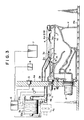
- Fig.3 is a longitudinal side elevation view of Fig.2.
- Fig.4 is a cross sectional top plan view of Fig.2.
- Fig.5 is a side elevation view partly broken away for showing an enlarged sensing part.
- Fig.6 is an enlarged front elevation view for showing an operating part.
- Fig.7 is an enlarged front elevation view for showing a water force adjusting control panel.
- Fig.8 is a time chart for use in performing a cleaning of a toilet bowl.
- Fig.9 is a time chart for use in performing a local cleaning and drying operation.
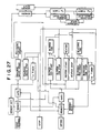
- Fig.10 is a flow chart for use in performing a cleaning of toilet bowl, a local cleaning and a drying operation.
- Fig.11 is a longitudinal side elevation view for showing another preferred embodiment of a toilet bowl.
- Fig.12 is a cross sectional view in top plan of Fig.11.
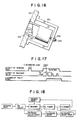
- Fig.13 is a longitudinal side elevation view for showing a toilet bowl.
- Fig.14 is a front elevation view partly broken away.
- Fig.15 is a top plan view partly broken away.
- Fig.16 is a side elevation view partly broken away for showing an enlarged fixing structure for a sensing part.
- Fig.17 is a time chart for use in performing a cleaning of a toilet bowl.
- Fig.18 is a flow chart of performing a cleaning operation.
- Fig.19 is a longitudinal side elevation in section for showing another preferred embodiment of a toilet bowl.
- Fig.20 is a front elevation view of Fig.19.
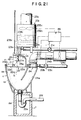
- Fig.21 is a longitudinal side elevation view for showing a hand washing bowl.
- Fig.22 is a front elevation view of Fig.21.
- Fig.23 is an enlarged front elevation view for showing a control panel for use in performing a manual control.
- Fig.24 is a time chart for use in performing a manual control.
- Fig.25 is a flow chart for use in performing a manual control.
- Fig.26 is a time chart for use in performing a manual control.
- Fig.27 is a flow chart for use in performing a manual control.
- Figs.28 and 29 are a longitudinal side elevation in section for showing another preferred embodiment of a hand washing bowl.
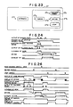
- Fig.30 is a time chart for use in performing an automatic control.
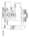
- Fig.31 is a flow chart for use in performing an automatic control.
- Fig.32 is a time chart for use in performing a manual control.
- Fig.33 is a flow chart for use in performing a manual control.
- FIG. 1 shows a case in which a toilet bowl (a), a toilet bowl (urinal) (b) and a hand washing bowl (c) are arranged in a unit room (A).
- the unit room (A) is formed with an air passage (A4) communicating with the interior of its floor (A1), interior of a side wall (A2) and interior of a ceiling (A3), and a grating (A5) having several vent holes therein is arranged over an entire floor surface, and in turn an entire ceiling wall is provided with air filters (A6).
- Interior air is forcedly circulated by a circulation blower (A7) arranged in the midway of the air passage (A4), thereby clean and fresh air is always supplied through air filters (A6) and the atmosphere in the room is kept clean.
- Each air filter (A6) is a high grade filter which can collect dusts of ultra fine particles and its efficiency of collection is more than 99.7 %.
- the toilet bowl (a) is provided with a water supplying part (1) for cleaning the interior of the toilet bowl (a) as shown in Figs.2 to 4, a local cleaning device (2) and local drying devices (3) constituting a local cleaning and drying device for use in cleaning a local part of a user and thereafter drying the local part, an air bleeding device (4) for discharging odor in the toilet bowl (a) and a control part (6) for receiving a sensing signal from a sensing part (5) for sensing a human body and a signal from an operating part (7) and for controlling each of the operations of the devices.
- a water supplying part (1) for cleaning the interior of the toilet bowl (a) as shown in Figs.2 to 4
- a local cleaning device (2) and local drying devices (3) constituting a local cleaning and drying device for use in cleaning a local part of a user and thereafter drying the local part
- an air bleeding device (4) for discharging odor in the toilet bowl (a)
- a control part (6) for receiving a sensing signal from a
- the water supplying part (1) is made such that a water passage (1a) communicating with a source of water is formed at an outer circumference of the toilet bowl (a), a water supplying pipe (1b) is connected to the water passage (1a), a solenoid valve (1c) is arranged in the midway of the water supplying pipe (1b), the solenoid valve (1c) is electrically connected to the control part (6), the solenoid valve (1c) is opened for a predetermined period of time under an instruction from the control part (6), a cleaning water is supplied to the water passage (1a) from the water supplying pipe (1b), the cleaning water is flowed along the inner wall of the toilet bowl (a) from several water flowing ports (1d) opened at the bottom wall of the water passage (1a) so as to clean the toilet bowl (a).
- the water supplying pipe (1b) and the solenoid valve (1c) are placed out of the unit room (A) so as not to hinder the flow of the clean air in the unit room (A) and then they are connected to the source of
- Cleaning water from the water supplying part (1) and sewage in the toilet bowl (a) are discharged out of the unit room (A) through a drain trap (1a) and a drain pipe (1f) connected to the drain trap.
- the local cleaning device (2) is made such that a cleaning water injection nozzle (2a) is arranged at the lower surface of a seat (a1), the nozzle (2a) is connected to the source of hot cleaning water through the water supplying pipe (2b) and the solenoid valve (2c), the solenoid valve (2c) is electrically connected to the control part (6), the solenoid valve (2c) is opened under an instruction from the control part (6), the cleaning water of desired temperature is supplied to the cleaning water injection nozzle (2a) through the water supplying pipe (2b), the nozzle (2a) injects the cleaning water toward the local part of the user so as to clean the local part.
- the cleaning water injection nozzle (2a) can be extended out or retracted from an opening (a2) of the seat (a1) and it is set such that its projection amount in respect to the opening (a2) is different in each of the anus cleaning and the cleaning with bidet, respectively.
- the water supplying pipe (2a) and the solenoid valve (2c) are out of the unit room (A) due to reasons similar to that found in case of the toilet bowl cleaning device.
- Local drying devices (3) are made such that hot air passages (3a) are defined within the seat (a1), the passages (3a) are connected to a hot air generating machine (3c) through air feeding pipes (3b) for guiding the passages out of the unit room (A), and the hot air generating machine (3c) is electrically connected to the control part (6).
- the hot air generating machine (3c) is operated under instructions from the control part (6) to feed the hot air to the hot air passages (3a), the hot air is injected toward the local part of the user from the injection ports (3d) opened at the front end walls of the passages (3a) so as to dry the local part of the user.
- the hot air generating machine (3c) is placed out of the unit room (A), and within the casing (32c) to which the suction pipe (31c) is connected are arranged in sequence a blower fan (33c), an air filter (34c) having a high efficiency of collection and a ceramic heater (35c) generating no oxides, and further the hot air generating machine has a less thermal loss and can supply clean hot air in such a way as the air does not pollute the interior of the unit room (A).
- An air bleeding device (4) is made such that an air bleeding passage (4a) is defined at an outer circumference of the seat (al), the bleeding passage (4a) is communicated with the forced discharging fan (4c) through discharging pipes (4b) for guiding the passages out of the unit room (A), the bleeding fan (4c) is electrically connected to the control part (6), the forced discharging fan (4c) is operated under the instructions from the control part (6), odor in the toilet bowl (a) is suctioned from the suction port (4d) opened to the bottom wall of the discharging passage (4a) and then discharged out of the unit room (A).
- a sensing part (5) is composed of a photoelectric sensor which is fixed at the rear upper position of the toilet bowl (a) at the rear wall (A8) of the unit room (A) and is electrically connected to the control part (6).
- the sensor detects a human body during a use of the toilet bowl, sends a sensed signal to the control part (6) and verifies the control part (6) that a beginning of the use of the toilet bowl is found.
- the sensing part (5) is made such that as shown in Fig.5 a light emitting and receiving element (5a) is inclined forwardly and downwardly, a sensing area is restricted near the toilet bowl (a) and an erroneous operation is prevented in such a case as, for example, other than the use of toilet bowl, i.e. a man merely passes by in front of the toilet bowl (a), it may not detect the human body.
- the operating part (7) is used for making a manual change-over operation between the local cleaning device (2) and the local drying devices (3), wherein as shown in Fig.6, a photoelectri sensor (7a) is assembled in the operating panel (7b) and arranged at the side upper position of the toilet bowl (a) at the side wall (A2) of the unit room (A).
- the operating part is electrically connected to the control part (6) and the photoelectrical sensor (7a) detects the hands of the user during a change-over operation and sends the sensed signal to the control part (6). That is, every time the user places his hands in front of the photoelectrical sensor (7a), operations of the local cleaning device (2) and the local drying devices (3) are changed over among a local cleaning, cleaning with bidet, drying and stop.
- Operation of the operating part (7) is allowed only when the sensing part (5) is operated, operation other than use of toilet bowl sensed by the sensing part (5) is prohibited and the cleaning water is prevented from accidentally being injected at the cleaning water injection nozzle (2a) in the local cleaning device (2) other than an occasion of use of the toilet bowl and further from being stained in the unit room (A).
- Receiving of a signal sent from the operating part (7) to the control part (6) is cancelled in case that a signal output time is in a desired period of time, e.g. less than 0.5 second, subsequent signals are also cancelled in case that output interval of signals is less than a desired period of time, e.g. less than 1 second, and operations of the local cleaning device (2) and the local drying device (3) are not unnecessarily changed over.
- the operating panel (7b) is provided with a display for indicating operating conditions of presence or absence of input of power supply and ranging from the cleaning to the stop and with light emitting diodes (7c) near the display for indicating the operations.
- a water force adjusting operating panel (8) for use in adjusting the water force from the cleaning water injection nozzle (2a) in the local cleaning device (2).
- the operating panel (8) is provided with the water force adjusting switches (8a) and (8b) as shown in Fig.7.
- the switches (8a) and (8b) are a so-called manual touch switch. These switches are relatively less frequently used and only a part of the finger tip is contacted with the switches, so a slight adhesion of hand stain may not generate any troubles at all.
- the sensing part (5) detects the human body and the sensed signal is sent to the control part (6).
- This sensed signal is cancelled within a desired time, e.g. within three seconds and useless operation of the water supplying part (1), local cleaning device (2) and the local drying devices (3) are prevented.
- the solenoid valve (1c) of the water supplying part (1) is opened and a preparatory cleaning of the toilet bowl (a) is carried out and at the same time the power supply for the operating part (7) is turned on. Further, when the sensing part (5) detects the human body and at the same time the forced discharging fan (4c) for the air bleeding device (4) is operated and the discharging or bleeding of odor is started under a suction at the suction port (4d).
- the reason why the preparatory cleaning is performed consists in the fact that water film is formed at the inner wall surface of the toilet bowl (a) in advance and the stains after use of the toilet bowl may easily be removed.
- the bleeding operation is continued during the use of toilet bowl in such a way as odor can be discharged without leaving it as well as for a desired period of time, for example, 15 seconds after the user moved away from the toilet bowl upon completion of the use of the toilet bowl, cleaning of the local part and drying of the local part and even after the output of the sensed signal of the sensing part (5) is stopped and after the output of the sensed signal is stopped.
- the user Upon completion of use of the toilet bowl, the user sets his hands in front of the photoelectrical sensor (7a) at the operating part (7) to cause the sensor (7a) to detect the hands, thereby the local cleaning device (2) starts to operate with the output of the first sensed signal and the cleaning of the local part is carried out with the cleaning water injected from the cleaning water injection nozzle (2a).
- a second sensing signal is outputted at the photoelectrical sensor (7a) at the operating part (7) again with a manual operation and a cleaning with bidet can be carried out.
- a third sensing signal is subsequently outputted at the photoelectrical sensor (7a) of the operating part (7), thereby the local drying devices (3) start to operate, hot air is blown from the blowing ports (3d) and then the local part is dried.
- a ceramic heater (35c) in the local drying devices (3) is started to heat when the sensing signal of the sensing part (5a) is outputted, and a hot air is fed instantly by a blower fan (33c) when the drying operation is started.
- a fourth sensing signal is outputted at the photoelectrical sensor (7a) of the operating part (7), thereby operation of the local drying devices (3) is stopped and the light emitting diode (7c) for displaying a stopped condition in the operating panel (7b) is illuminated for about one second.
- the power supply for the operating part (7) is kept turned off, so that the operating part (7) does not detect the human body so long as the sensing part (5) does not output any sensing signals, and it does not produce any outputs and thus it is possible to prevent any erroneous operations of the local cleaning device (2) and the local drying devices (3).
- the local cleaning device (2) and the local drying devices (3) continue their operations within a desired period of time set by the control part (6) until the operating part (7) produces a new sensed signal, and stops automatically after the desired period of time is elapsed.
- the set time is set to, for example, 5 minutes in case of performing the local cleaning and the cleaning with bidet, and it is set to 10 minutes for example in case of performing the local drying operation.
- an alarm device After the set time is elapsed, an alarm device will be operated after the local cleaning device (2) and the local drying devices (3) are stopped and will generate an alarm.
- Figs.11 and 12 illustrate another preferred embodiment of a toilet bowl (a), wherein fixing frames (9) are integrally assembled and formed at the rear part of the toilet bowl (a). Within the fixing frames (9) are fixed and arranged the water supplying part (1), local cleaning device (2), local drying devices (3), functioning part of the discharging device (4) and the control part (6). Cover panels (10) are fixed between the fixing frames (9), thereby covers the functioning part of each of the devices and the control part (6) so as to make a unified assembly.
- the fixing frames (9) are assembled in a box-like form higher than the toilet bowl (a) and the seat (a1), a sensing part (5) is fixed to the cover panel (10) covering the front surface and at the same time a cord (6a) pulled out of the control part (6) can be connected to a power supply cord (6b) arranged out of the cover panel (10).
- the functioning part of the water supplying part (1) corresponds to the water supplying pipe (1b) and the solenoid valve (1c), the base end of the water supplying part (1b) is passed through the cover panel (10) and projected outward and further can be connected to a main water supplying pipe (1h) through a connector (1g).
- the base end of the drain pipe (1f) connected to the toilet bowl (a) is similarly passed through the cover panel (10), projected outwardly and can be connected to the drain main pipe (1j) through a connector (1i).
- the functioning part of the local cleaning device (2) corresponds to the water supplying pipe (2b) and the solenoid valve (2c) except the cleaning injection nozzle (2a) and to a hot water heater (2d) connected to the extremity end of the water supplying pipe (2b) as shown in the drawings, the hot water heater (2d) is mounted on and fixed to a mounting plate (2e) arranged within the fixing frames (9) and at the same time connected to the midway part of the water supplying pipe (1b) of the water supplying part (1) through a branch pipe (2f).
- the functioning part of the local drying devices (3) corresponds to the air blowing pipe (3b) and the hot air generating machine (3c), the base end of the suction pipe (31c) of the hot air generating machine (3c) is passed through the cover panel (10), projected outwardly and can be connected to the suction main pipe (3d).
- the functioning part of the bleeding device (4) corresponds to a bleeding pipe (4b) and a forced bleeding fan (4c), the base end of the bleeding pipe (4b) is passed through the cover panel (10), projected outwardly and can be connected to the main bleeding pipe (4d).
- Figs.11 and 12 can be completed on site only by connecting a power supply code (6b), main water supplying pipe (1h), drain main pipe (1j), suction main pipe (3d) and bleeding main pipe (4d). Since this system has no troublesome operation found in Figs.3 and 4 in which the functioning part of each of the devices and the control part (6) are separately arranged and thereafter they must be connected to each other, resulting in that their mounting work is quite simple and convenient.
- the toilet bowl (b) is provided with a water supplying part (11) for cleaning the interior of the toilet bowl (b) and a control part (13) for receiving a sensed signal from a sensing part (12) sensing the human body and for controlling the operation of the water supplying part (11).
- the water supplying part (11) has a water passage (11a) along an entire circumference of the opening (b1), the water passage (11a) is connected to a water supplying source through the water supplying pipe (11b) extending out of the unit room (A), a solenoid valve (11c) is arranged in the water supplying pipe (11b), the solenoid valve (11c) is electrically connected to the control part (13), the solenoid valve (11c) is opened under instructions from the control part (13), the cleaning water is supplied from the water supplying pipe (11b) to the water passage (11a).
- the cleaning water is flowed from several water flowing holes (11d) opened at the bottom wall of the water passage (11a) along the inner wall of the toilet bowl (b) so as to clean the interior of the toilet bowl (b).
- the cleaning water and sewage from the water supplying part (11) are discharged out of the unit room (A) from the toilet bowl (b) through a drain trap (11e) and a drain pipe (11f).
- the sensing part (12) is comprised of a photoelectric sensor, detects a human body standing in front of the toilet bowl (b) in case of using the toilet bowl, sends the sensed signal to the control part (13), causes the control part (13) to acknowledge the starting of use of the toilet bowl, and the sensing part is fixed in flush with the upper front wall (b2) of the toilet bowl (b) in such a way as it may not hinder the flow of clean air within the unit room (A).
- a fixing structure for the sensing part (12) is constructed as shown in Fig.16, wherein the sensing part (12) is inserted and fixed to a front wall (b2) of the toilet bowl (b) through a fixing hole (b3), a front end flange (12a) of the sensing part (12) is abutted against an outer surface of the front wall (b2) and in turn a fixing threaded shaft (12b) at the rear end is fixed to the inner surface of the front wall (b2) through bracket (12c) and nut (12d).
- the sensing part (12) detects the human body and sends the sensed signal to the control part (13). This sensed signal will be cancelled in case that the output has a desired period of time, for example, within three seconds, and a useless operation of the water supplying part (11) will be prevented.
- the solenoid valve (11c) of the water supplying part (11) When the sensed signal is inputted to the control part (13) more than three seconds, the solenoid valve (11c) of the water supplying part (11) will be opened under the instructions from the control part (13) and then the cleaning of the toilet bowl (b) will be started before using of the toilet bowl.
- a duration of the solenoid valve (11c) is one second, the solenoid valve (11c) is closed after the time of opening of the valve is elapsed, the valve will be opened again after six seconds and periodical opening and closing operation of the solenoid valve (11c) is repeated by several times within a period of using the toilet bowl.
- the valve opening time or valve closing time of the solenoid valve (11c) is counted by a timer at the control part (13) and the solenoid valve (11c) is opened or closed with a period of setting time at the control part.
- a proper amount of cleaning water is supplied into the toilet bowl (b) continuously from before starting of use of the toilet bowl to after completion of use of the toilet bowl under a periodical opening and closing operation of the solenoid valve (11c), a water film is always formed at the inner wall of the toilet bowl (b), the bowl is cleaned without remaining any urine component and no odor may be produced. That is, even if the user moves away from a front part of the toilet bowl (b) upon completion of use of the bowl and input of the sensing signal from the sensing part (12) to the control part (13) is stopped, the cleaning water supplied under the opening of the solenoid valve (11c) before its stoppage cleans the interior of the toilet bowl (b).
- Figs.19 and 20 illustrate another preferred embodiment of the toilet bowl (urinal) (b), wherein the fixing frames (14) are integrally assembled and formed at the rear part of the toilet bowl (b), the functioning part of the water supplying part (11) and the control part (13) are fixed and arranged in the fixing frames (14), cover panels (15) are fixed between the fixing frames (14) so as to cover the functioning part of the water supplying part (11) and the control part (13) to make a unified assembly.
- the fixing frames (14) are assembled to form a box-like shape slightly higher than the height of the toilet bowl (b) and a code (13a0 pulled out of the control part (13) can be connected to a power supply code (13b) arranged outside of the cover panel (15).
- the functioning part of the water supplying part (11) corresponds to a water supplying part (11b) and a solenoid valve (11c), a base end of the water supplying pipe (11b) is passed through the cover panel (15), projected outwardly and can be connected to a main water supplying pipe (11h) through a connector (11g).
- the base end of the drain pipe (11f) connected to the toilet bowl (b) is passed through the cover panel (15) in the same manner as that of the water supplying pipe (11b), projected outwardly and can be connected through a main drain pipe (11j).
- the system shown in Figs.19 and 20 is completed in its work on site merely by connecting the power supply code (13a), water supplying main pipe (11h) and the drain main pipe (11j) and this system may eliminate a troublesome work such as a separate mounting of the functioning part of the water supplying part (11) and the control part (13) and then a connection of these elements as found in Figs.13 to 15, resulting in that an installing work becomes simple and a convenient work is assured.
- the hand washing bowl (c) is supported by a mounting block (c') placed out of the unit room (A), only its front opening part (c1) and a front wall (c2) around the opening are adjacent to the interior of the unit room (A) from the rear wall (A8).
- the hand washing bowl (c) is provided with a hand washing water injection device (21) constituting a water supplying part, a bowl cleaning device (22), a hot air heater (23) for drying hands, air bleeding device (24) in the bowl (c) and a control part (26) for controlling an operation of each of the devices by receiving a sensed singal from a sensing part (25) for sensing the hands when the hands are washed.
- a sensing part for sensing the hands when the hands are washed.
- Each of the devices and the control part (26) are arranged within the hand cleaning bowl (c) or out of the unit room (A) so as not to prevent a flow of clean air in the unit room (A).
- the hand washing water injection device (21) is arranged such that the water injection nozzle (21a) is displaced from an intermediate position of a width direction outwardly on the upper wall surface (c4) of the bowl part (c3) in the hand washing bowl (c) and is fixed to face downward.
- the nozzle (21a) is connected to a water supplying source through the water supplying pipe (21b) having a solenoid valve (21c) therein, the solenoid valve (21c) is electrically connected to the control part (26), the solenoid valve (21c) is opened for a specified period of time under the instructions from the control part (26) to supply the cleaning water to the injection nozzle (21a) and the nozzle (21a) injects the hand washing water into the bowl (c3).
- the injection nozzle (21a) is inclined by a desired angle toward a vertical line passing through an intermediate position in a width direction of the hand washing bowl (c).
- the bowl cleaning device (22) has an annular water passage (22a) at the upper circumferential part of the bowl (c3), the water passage (22a) is connected to the water supplying source through a water supplying pipe (22b) provided with the solenoid valve (22c).
- the solenoid valve (22c) is electrically connected to the control part (26) , the solenoid valve (22c) is opened under instructions from the control part (26), the cleaning water is supplied to the water passage (22a), is flowed from several water flowing holes (22d) opened at the bottom wall of the water passage (22a) along the inner wall of the bowl (c3) so as to clean the interior of the bowl (c3).
- the cleaning water from the bowl cleaning device (22) is discharged out of the hand washing bowl (c) and unit room (A) together with the cleaning water from the hand washing water injection device through a drain trap (22e) and a drain pipe (22f).
- a hot air heater (23) is provided with a hot air injection nozzle (23a) at the upper wall surface (c4) of the bowl part (c3) at a position in its width direction which is symmetrical to the injection nozzle (21a).
- the nozzle (23a) is connected to the hot air generating machine (23c) through a flexible pipe (23b), the hot air generating machine (23c) is electrically connected to the control part (26).
- the hot air generating machine (23c) is operated for a desired period of time under instructions from the control part (26) to send the hot air to the injection nozzle (23a) and then the hands are dried by hot air blown from the nozzle (23a).
- the injection nozzle (23a) is inclined at the same angle as that of the water injection nozzle (21a) toward the vertical line passing through an intermediate position in a width direction of the hand washing bowl (c). Therefore, putting the hands at the intermediate position in a width direction in the hand washing bowl (c) causes both cleaning water from the water injection nozzle (21a) and hot air from the injection nozzle (23a) to be applied to the hands without moving them.
- the hot air generating machine (23c) is made such that a blower fan (233c), air filter (234c) and ceramic heater (235c) are arranged in sequence from the upstream side within a casing (232c) to which a suction pipe (231c) is connected. A thermal loss is less and a clean hot air can be fed in such a way as the clean air in the unit room (A) is not polluted.
- the air bleeding device (24) in the bowl (c3) is placed adjacent to the rear part of the bowl (c3) to form air bleeding passage (24a), the air bleeding passage (24a) is connected to a forced air bleeding fan (24c) through an air bleeding pipe (24b) and at the same time the air bleeding fan (24c) is electrically connected to the control part (26), the forced air bleeding fan (24c) is operated for a specified period of time under instructions from the control part (26) to suck dusts such as effete matter of hands dropped into the bowl (c3) under chafing of hands during drying of hands from the air bleeding passage (24a) together with hot air and then discharge them.
- the sensing part (23) is comprised of a photoelectric sensor which is arranged at a position in the upper wall surface (c4) of the bowl held between the water injection nozzle (21a) and the blowing nozzle (23a), that is, an intermediate position in a width direction of the hand cleaning bowl (c), and as shown in Fig.21, an optical axis ( l1 ) of light emitting and light receiving element is inclined downward and forward by a desired angle in respect to a vertical line.
- the inclination of the optical axis ( l1 ) is made in order to enable the sensing part (25) to positioned slightly deeper from the opening (c5) of the hand washing bowl (c), to prevent any erroneous operation of the sensing part (25) caused by an accidental cutting of the light beam emitted from the light emitting element with hands and to enable a rapid sensing of hands to be performed when the hands are put into the hand washing bowl (c) through the opening (c5) in case of washing hands.
- the operating panel (27) is arranged at the side position of the hand washing bowl (c) at the rear wall (A8) of the unit room (A).
- the operating panel: (27) is provided with a hand washing switch (27a) and a drying switch (27b) of push-button type, light emitting diodes (27c), (27d) indicating the input condition of the switches, as shown in Fig.23, and similarly it is provided with a stop switch (27e) of a push button type switch and with light emitting diodes (27f0, (27g) for displaying either an automatic control or a manual control and for indicating its operation, and further it is electrically connected to the control part (26).
- the sensing part (25) detects the hands and sends the sensed signal to the control part (26).
- Input of a sensing signal to the control part (26) is only first time of inputting operation and the sensed signals outputted subsequent to the first input time are prohibited from being input to the control part (26).
- the solenoid valve (21c) for the hand washing water injection device (21) is opened for a desired period of time, for example, 10 seconds, under instructions from the control part (26) and the cleaning water for washing hands is injected from the water injection nozzle (21a).
- the solenoid valve (22c) for the bowl cleaning device (22) is opened in simultaneous with the injection of the cleaning water from the water injection nozzle (21a) and then the cleaning in the bowl (c) is started.
- Time of opening of the solenoid valve (22c) is for one second, the solenoid valve (22c) is closed after this valve opening time is elapsed and then the valve is opened again after six seconds. Such a periodic opening and closing of the solenoid valve (22c) is repeated by several times within a hand washing time. Valve opening and closing time of the solenoid valve (22c) is counted by a timer at the control part (26) and the solenoid valve (22c) is opened or closed at a period of specified time at the control part (26).
- the hot air generating device (23) and air bleeding device (24) simultaneously start their operation after a desired time, for example, 5 seconds is elapsed and then the hand drying and the air bleeding of the bowl part (c3) are carried out.
- a delay time is made between a starting of operation of the hot air heater (23) and the air bleeding device (24) and a stoppage of operation of the hand washing water injection device (21) and the bowl cleaning device (22) consists in that the cleaning water or sewage remained in the bowl part (c3) is prevented from being splashed out of the bowl part (c3) with hot air produced from the hot air heater (23) and the air bleeding device may not badly affected under a suction of the cleaning water into the air bleeding device.
- the hot air heater (23) is operated such that air is heated during its passage through the ceramic heater (235c) under a rotation of the blower fan (233c) in the hot air generating machine (23c), the hot air is blown from the blowing nozzle (23a), struck against the hands to dry them.
- the ceramic heater (235c) is already started to heat when the sensed signal is inputted to the control part (26) and the hot air may instantly be fed by the blower fan (233c) when the drying operation is started.
- the air bleeding device (24) is operated such that the bowl part (c3) is suctioned through the air bleeding passage (24a) under a rotation of the forced air bleeding fan (24c), an operating time of the fan (24c) is counted by a timer at the control part (26), the fan (24c) is operated within a specified period of time at the control part (26) and then its operation is stopped after the desired delay time, for example, 5 seconds is elapsed after the operation of the hot air generating device (23) is stopped.
- the reason why this delay time is made consists in the fact that dusts such as waste matters produced by scrubbing of hands after drying of hands is discharged out of the bowl part (c3) without being remained in it.
- the stop pushbutton switch (27e) at the operating panel (27) is depressed and the operation performed under an automatic control is stopped and reset to its initial condition, and thereafter either the hand washing switch (27a) or the drying switch (27b) is depressed to change-over the automatic control to the manual control. Even if both the hand washing switch (27a) and the drying switch (27a) are depressed during the automatic control operation, its input is not received at the control part (26).
- both hand washing water injection device and (21) and bowl cleaning device (22) are simultaneously started to operate in the same manner as that of the automatic control so as to perform both cleaning of hands and bowl part (c3).
- either the stop switch (27a) or the drying switch (27b) is depressed.
- the hot air heater (23) and the air bleeding device (24) are started to operate with a delay of desired time in the same manner as that of the automatic control after the injection of cleaning water is stopped, a change-over from the hand washing operation to the drying operation is performed.
- the hands can be dried for a desired period of time under an operation of the hot air heater (23) in the same manner as above.
- the stop switch (27e) or the hand washing switch (27a) is depressed, and in case of depressing of the hand washing switch (27a), the operation is changed-over to the hand cleaning operation with a delay time in the same manner as that of the automatic control.
- FIG.28 and 29 illustrates another preferred embodiment of the hand washing bowl (c) respectively.
- the system shown in Fig.28 is made such that fixing frames (28) are integrally assembled and formed from the bottom part of the hand washing bowl (c) to the upper part thereof through a rear part, and the cleaning water injection device (21), bowl cleaning device (22), hot air heater (23), the functioning part of air bleeding device (24) and the control part (26) are fixed and arranged in the fixing frames (28), and at the same time a cover panel (29) is fixed over the fixing frames (28), thereby it covers the functioning part of each of the devices and the control part to make a unified device.
- the fixing frames (28) are comprised of a mounting block (28a) and a frame (28b) formed in a longitudinal box-like shape and faced upwardly from the mounting block (28a), the hand washing bowl (c) is mounted and fixed on the mounting block (28a), a front opening (c1) of the hand washing bowl (c) and a front wall (c2) around the opening are projected out of the cover panel (29) and at the same time a cord (26a) pulled out of the control part (26) can be connected to a power supply cord (26b) arranged outside of the cover panel (26b).
- the functioning part of the cleaning water injection device (21) corresponds to the water supplying pipe (21b) and the solenoid valve (21c) except the water injection nozzle (21a), a base end of the water supplying pipe (21b) is passed through the cover panel (29), projected outwardly and can be connected to the main water supplying pipe (21e) through a connector (21d).
- the functioning part of the bowl cleaning device (22) corresponds to the water supplying pipe (22b) and the solenoid valve (22c), and a base end of the water supplying pipe (22b) is connected to the midway part of the water supplying pipe (21b) of the toilet cleaning water injection device (21) through a branch pipe (22b), thereby cleaning water is supplied.
- a base end of the drain pipe (22f) to be connected to the hand washing bowl (c) is also passed through the cover panel (29) in the same manner as that of the water supplying pipe (21b), projected outwardly and can be connected to the main drain pipe (22i) through a connector (22h).
- the functioning part of the hot air heater (23) corresponds to a flexible pipe (23b) and a hot air generating machine (23c) except a blowing nozzle (23a), and the hot air generating machine (23c) is mounted and fixed on a mounting plate (32d) arranged in the fixing frames (28).
- the functioning part of the air bleeding device (24) corresponds to a air bleeding pipe (24b) and a forced air bleeding fan (24c), a base end of the air bleeding pipe (24b) is passed through the cover panel (29), projected outwardly and can be connected to the main air bleeding pipe (24d).
- system shown in Fig.28 is completed in its work on site by a mere connection of a power supply code (26b), a main water supplying pipe (21e), a main drain pipe (22i) and a main air bleeding pipe (24d) and it does not require any troublesome operation in which the functioning part of each of the devices and the control part (26) are separately mounted and then they must be connected to each other as shown in Figs.21 and 22, resulting in that a mounting work becomes simple and convenient.
- a system shown in Fig.29 is made such that an hot air generating machine (23c) of a hot air heater (23) and an air bleeding passage (24a0 formed adjacent to the rear part of the bowl part (c3) are connected by a suction and air bleeding pipe (23e).
- the air fed through the suction and air bleeding pipe (23e) from within the bowl part (c3) under a rotation of the blower fan (233c) of the hot air generating machine (23c) is heated while it is passed through the ceramic heater (235c), and then the hot air is blown from the blowing nozzle (23a) to dry the hands and at the same time dusts such as waste matters generated under a scrubbing of both hands while drying operation is suctioned and then the waste matters are removed while they are passed through the air filter (234c), and they are circulated.
- the system shown in Fig.29 can be installed more easily than that of Fig.28 due to the fact that the air bleeding device and the main air bleeding pipe are not required to have a connection on site.
- the present preferred embodiments show that the toilet bowls (a) and (b) and the hand washing bowl (c) are installed in the unit room (A), it is not necessarily required to install three units (a), (b) and (c) and for example, two units of toilet bowls (a) and (b) or two units of toilet bowl (b) and the hand washing bowl (c) may be installed.
Claims (20)
- Sanitärraumeinheit (A) umfassend:
einen Toilettenaufbau mit einer Toilettenschüssel (a);
einer Wasserversorgung (1) zur Speisung von
Reinigungswasser zu der Innenfläche der
Toilettenschüssel (a) unter Ausbildung eines
Wasserfilms auf ihrer Innenfläche;
dadurch gekennzeichnet, daß- die Sanitärraumeinheit (A) für den Einbau in einen Rechnerraum oder einen anderen Reinraum geeignet ist;- diese Sanitärraumeinheit Einrichtungen (A1 bis A7) zur Aufrechterhaltung einer reinen Atmosphäre in der Raumeinheit aufweist; und,- daß die Toilettenschüssel (a) eine örtliche Reinigungsvorrichtung (2) zum Hervorspritzen von Wasser auf den Anus eines Benutzers der Toilette oder zum Hervorspritzen von Wasser wie in einem Bidet aufweist;- eine Heißlufterzeugungsvorrichtung und eine damit verbundene Blasvorrichtung (3c) vorgesehen sind, um heiße Luft von der Toilette auf die gewaschenen Teile des Toilettenbenutzers zu richten;- der Toilettenaufbau ein Erkennungsteil (5) zum Erkennen eines menschlichen Körpers während der Benutzung der Toilettenschüssel, ein Steuerteil (6), welches dazu dient, die Wasser- und Heißluftversorgung zu der Toilettenschüssel in Antwort auf ein Signal des Erkennungsteiles (5) bei Erkennung eines menschlichen Körpers zu steuern, einen Betätigungsteil (7), welcher einen Betriebswechsel der örtlichen Reinigungseinrichtung (2) und der Heißlufterzeugungsvorrichtung (3c) erlaubt, beinhaltet, wobei der Toilettenaufbau derart ausgebildet ist, daß das Betätigungsteil (7) nur diesen Wechsel durchführen kann, wenn das Erkennungsteil (5) einen menschlichen Körper, welcher die Toilette benutzt, erkennt. - Toilettenaufbau nach Anspruch 1,
dadurch gekennzeichnet, daß
das Betätigungsteil (7) zum Wählen folgender Operationen verwendet werden kann: (a) Betätigung der örtlichen Reinigungseinrichtung (2) zum Richten von Wasser auf den Anus eines Toilettenbenutzers;(b) Betatigung der lokalen Reinigungseinrichtung (2) zum Richten von Wasser wie beim Bidet auf einen Toilettenbenutzer; (c) Betätigung der Heißlufterzeugungsvorrichtung; (d) Stoppen dieser Betätigungen. - Toilettenaufbau nach Anspruch 1 oder 2,
dadurch gekennzeichnet, daß
das Bedienungsteil (7) einen photoelektrischen Sensor (7a) aufweist, welcher auf eine Hand eines Toilettenbenutzers zum Senden eines Signales an das Steuerteil (6) anspricht, um diesen Betriebswechsel jedesmal, wenn der Toilettenbenutzer eine Hand vor den photoelektrischen Sensor (7a) hält, zu bewirken. - Toilettenaufbau nach einem der Ansprüche 1 bis 3,
dadurch gekennzeichnet, daß
das Steuerteil (6) bewirkt, daß das Wasserversorgungsteil (1) für eine Zeitspanne betätigt wird, nachdem das Erkennungsteil (5) feststellt, daß ein menschlicher Körper die Toilette benutzt, wobei das Steuerteil (6) abermals den Wasserversorgungsteil (1) für eine Zeitspanne betätigt, nachdem das Erkennungsteil (5) feststellt, daß der menschliche Körper die Toilette freigemacht hat. - Toilettenaufbau nach einem der Ansprüche 1 bis 4,
dadurch gekennzeichnet, daß
er eine Entlüftungsvorrichtung (4) zum Entfernen von Geruch aus der Toilettenschüssel umfaßt, das Steuerteil (6) bewirkt, daß die Entlüftungsvorrichtung (4) von einem Zeitpunkt an betätigt wird, wenn die Erkennungseinrichtung (5) einen menschlichen Körper erfaßt, bis zu einem vorher bestimmten Zeitpunkt, nachdem die Erkennungseinrichtung (5) festgestellt hat, daß der menschliche Körper die Toilette freigemacht hat. - Sanitärraumeinheit geeignet zur Installation in einen Rechnerraum oder einen Reinraum, wobei die Sanitärraumeinheit einen Toilettenaufbau gemäß einem der Ansprüche 1 bis 5 aufweist.
- Sanitärraumeinheit nach Anspruch 6,
dadurch gekennzeichnet, daß
Belüftungslöcher in ihrem Boden angeordnet sind und Luftdurchlässe (A4) mit dem Inneren des Raumes (A1) und dem Inneren einer Decke der Sanitärraumeinheit kommunizieren. - Sanitärraumeinheit nach Anspruch 7,
dadurch gekennzeichnet, daß
sie ein Zirkulationsgebläse (A7) zur Versorgung frischer Luft zur Sanitärraumeinheit über Filter (A6) und ihre Durchgänge beinhaltet. - Sanitärraumeinheit nach einem der Ansprüche 6 bis 8,
dadurch gekennzeichnet, daß
Befestigungsrahmen (9) integriert zusammengesetzt und an einem hinteren Teil der Toilettenschüssel (a) ausgebildet sind; das Wasserversorgungsteil (1), die Entlüftungsvorrichtung (4), das Steuerteil (6) und die Heißlufterzeugungsvorrichtung mit der zugehörigen Gebläseeinrichtung (3c) in den Befestigungsrahmen (9) befestigt und angeordnet sind; und, daß eine Abdeckblende (10) über diesen Befestigungsrahmen (9) befestigt ist, um eine Abflußeinrichtung (1f) und die Teile (1,6), Vorrichtungen (4,3c) und Einrichtungen (3c), welche in den Befestigungsrahmen (9) angeordnet sind, abzudecken. - Sanitärraumeinheit nach einem der Ansprüche 6 bis 9,
dadurch gekennzeichnet, daß
sie ein Pissoir (b) umfaßt. - Sanitärraumeinheit nach Anspruch 10,
dadurch gekennzeichnet, daß
die Wasserversorgungseinrichtung (11) für das Pissoir betätigt wird, wenn eine Erkennungseinrichtung (12) einen menschlichen Körper an dem Pissoir erfaßt. - Sanitärraumeinheit nach Anspruch 11,
dadurch gekennzeichnet, daß
die Befestigungrahmen (14) integriert zusammengesetzt und am hinteren Teil des Pissoirs (b) ausgebildet sind; die Wasserversorgungsvorrichtung (11) und ein Steuerteil (13) für die Wasserversorgungseinrichtung beide in den Befestigungsrahmen (14) gehalten sind; daß eine die Wasserversorgungseinrichtung (11) und das Steuerteil (13) abdeckende Blende (15) an den Befestigungsrahmen (14) angebracht ist; und daß das Steuerteil (13) von dem Erkennungsteil (12) gesteuert wird. - Sanitärraumeinheit nach einem der Ansprüche 6 bis 12,
dadurch gekennzeichnet, daß
sie ein Handwaschbecken (c) umfaßt. - Sanitärraumeinheit nach Anspruch 13,
dadurch gekennzeichnet, daß
ein Lufterhitzer (23) mit einem Handerkennungsteil (25) zur Inbetriebsetzung des Lufterhitzers (23) nach einer Betätigung der Wasserversorgungseinrichtung (21) zum Händetrocknen vorgesehen ist. - Sanitärraumeinheit nach Anspruch 14,
dadurch gekennzeichnet, daß
eine Entlüftungsvorrichtung (24) zum Abziehen von Luft an dem Handwaschbecken (c) und eine Vorrichtung zum gleichzeitigen Betätigen der Entlüftungsvorrichtung (24) und des Lufterhitzers (23) als Antwort auf eine Erfassung von Händen an dem Waschbecken durch die Erkennungseinrichtung (25), vorgesehen sind. - Sanitärraumeinheit nach Ansprüchen 14 oder 15,
dadurch gekennzeichnet, daß
sie Einrichtungen (22b, 22c) zum Speisen von Reinigungswasser zu dem Waschbecken, um es zu waschen, wobei diese Einrichtung zusätzlich zur Einrichtung (21, 21c) zum Speisen von Handwaschwasser vorgesehen ist und einer Einrichtung zum Absperren des Wassers zu beiden Wasserversorgungseinrichtungen, wenn der Lufterhitzer (23) in Betrieb genommen wird, beinhaltet. - Sanitärraumeinheit nach Anspruch 16,
dadurch gekennzeichnet, daß
manuell betätigbare Schalter (27) zum Steuern der Wasserversorgungseinrichtung und des Lufterhitzers vorgesehen sind. - Sanitärraumeinheit nach Anspruch 15,
dadurch gekennzeichnet, daß
Steuereinrichtungen (26) vorgesehen sind, welche bewirken, daß die Entlüftungsvorrichtung (24) ihren Betrieb für eine bestimmte Zeitdauer, nachdem der Betrieb der Heißlufterzeugungseinrichtung (23) gestoppt wurde, fortsetzt. - Sanitärraumeinheit nach einem der Ansprüche 14 bis 18,
dadurch gekennzeichnet, daß
ein Filter (234c) an einer Auslaßseite des Lufterhitzers (23c) angeordnet ist. - Sanitärraumeinheit nach einem der Ansprüche 14 bis 19,
dadurch gekennzeichnet, daß
die Befestigungsrahmen (28) mit der Waschschüssel (c) integriert zusammengesetzt und an ihr ausgebildet sind, und daß eine Abdeckblende (29) über den Befestigungsrahmen (28) angebracht ist, um die Wasserversorgungseinrichtung (21), den Lufterhitzer (23), die Einrichtung zur Betätigung der Entlüftungsvorrichtung (24) und ein Steuerteil (26) für den Lufterhitzer (23) und die Wasserversorgungseinrichtung (21) abzudecken.
Applications Claiming Priority (4)
| Application Number | Priority Date | Filing Date | Title |
|---|---|---|---|
| JP59230860A JPS61109836A (ja) | 1984-10-31 | 1984-10-31 | 衛生装置 |
| JP230852/84 | 1984-10-31 | ||
| JP230860/84 | 1984-10-31 | ||
| JP59230852A JPS61109833A (ja) | 1984-10-31 | 1984-10-31 | クリ−ンル−ム用衛生設備ユニツト |
Publications (3)
| Publication Number | Publication Date |
|---|---|
| EP0180236A2 EP0180236A2 (de) | 1986-05-07 |
| EP0180236A3 EP0180236A3 (en) | 1987-08-19 |
| EP0180236B1 true EP0180236B1 (de) | 1991-03-06 |
Family
ID=26529574
Family Applications (1)
| Application Number | Title | Priority Date | Filing Date |
|---|---|---|---|
| EP85113894A Expired - Lifetime EP0180236B1 (de) | 1984-10-31 | 1985-10-31 | Raum mit sanitären Einrichtungen für die Reinraumtechnik |
Country Status (4)
| Country | Link |
|---|---|
| US (1) | US4692951A (de) |
| EP (1) | EP0180236B1 (de) |
| KR (1) | KR910008895B1 (de) |
| DE (1) | DE3582007D1 (de) |
Families Citing this family (38)
| Publication number | Priority date | Publication date | Assignee | Title |
|---|---|---|---|---|
| KR920003844B1 (ko) * | 1984-10-12 | 1992-05-15 | 도오도오 기기 가부시기가이샤 | 클린룸용 위생설비기구 |
| FR2601402B1 (fr) * | 1986-07-11 | 1988-11-25 | Martinval Andre | Installation d'aisances avec dispositif de lavage, desinfection et sechage des abattants de la cuvette d'aisances. |
| NL8603230A (nl) * | 1986-12-18 | 1988-07-18 | Struyk Beheer B V En Amerglass | Toilet voor openbaar gebruik. |
| FR2613398A1 (fr) * | 1987-03-30 | 1988-10-07 | Vivier Harry | Installation de w.c. autonettoyante de la cuvette et du siege |
| DE8711488U1 (de) * | 1987-08-25 | 1988-01-28 | Chien, Min-Teh, Taipeh/T'ai-Pei, Tw | |
| US5184355A (en) * | 1988-04-22 | 1993-02-09 | Inax Corporation & Nippondenso Co., Ltd. | Water closet blowing warm air and water closet unit attachable to toilet room |
| DE68900280D1 (de) * | 1988-04-22 | 1991-10-31 | Inax Corp | Wasserklosett mit warmluftgeblaese und wasserklosetteinheit, befestigbar in einem toilettenraum. |
| JP2690107B2 (ja) * | 1988-06-25 | 1997-12-10 | 東陶機器株式会社 | 小便器 |
| IT1229331B (it) * | 1989-05-03 | 1991-08-08 | Tecnobios S R L | Dispositivo automatico per la pulizia delle mani e relativo procedimento. |
| WO1992003620A1 (en) * | 1990-08-20 | 1992-03-05 | Redford Daniel S | Environmentally controlled toilet |
| CA2050185C (en) * | 1990-09-11 | 1996-07-16 | Eiichi Tanaka | Cleansing control apparatus |
| KR960010614Y1 (ko) * | 1993-11-23 | 1996-12-20 | 최한선 | 변기의 위생제어장치 |
| US5539938A (en) * | 1993-12-08 | 1996-07-30 | Tubbs; Elton H. | Water closet |
| US5691919A (en) * | 1995-02-28 | 1997-11-25 | Kimberly-Clark Worldwide, Inc. | System and method for collecting data on tissue consumption |
| IT1289114B1 (it) * | 1996-06-12 | 1998-09-25 | N T S Nuove Tecnologie Sanitar | Impianto automatico per la pulizia igienica post funzioni fisiologiche |
| IT1288420B1 (it) * | 1997-01-22 | 1998-09-22 | Roberto Agosti | Impianto igienico-sanitario autopulente per uso pubblico |
| EP1050632A1 (de) * | 1999-05-06 | 2000-11-08 | Danfo Sanitetsystem AB | Autmatische öffentliche WC-Kabine |
| ATE261166T1 (de) * | 1999-12-13 | 2004-03-15 | Urimat Holding Ag | Verfahren zur übertragung und auswertung von werbung und informationen in toilettenanlagen und eine displayanordnung zur durchführung des verfahrens in einem pissoir- oder toilettenraum |
| US6799264B2 (en) | 2001-02-20 | 2004-09-28 | Koninklijke Philips Electronics N.V. | Memory accelerator for ARM processor pre-fetching multiple instructions from cyclically sequential memory partitions |
| US6862754B1 (en) * | 2003-08-22 | 2005-03-08 | American Standard International Inc. | Dual phase flush urinal |
| US7320146B2 (en) * | 2005-05-12 | 2008-01-22 | Sloan Valve Company | Sensor plate for electronic flushometer |
| US8387171B2 (en) * | 2006-04-14 | 2013-03-05 | Bowles Fluidics Corporation | Microflush urinal with oscillating nozzle |
| WO2008019526A1 (fr) * | 2006-08-07 | 2008-02-21 | Zufu Chen | Cuvette des w.c. avec fonctions de chauffage du siège et de désodorisation |
| US8060952B2 (en) * | 2006-09-19 | 2011-11-22 | Robert Shaul | Odor removal system and overflow safety system for toilets |
| GB2444057A (en) * | 2006-11-23 | 2008-05-28 | Geoffrey John Weavell | Odourless toilet |
| EP2067901B2 (de) * | 2007-12-05 | 2018-07-25 | Geberit International AG | Einrichtung mit einer Spülvorrichtung und einem Klosettkörper, Montageset zum Montieren einer solchen Einrichtung sowie Verfahren zum Montieren der genannten Einrichtung |
| KR101445471B1 (ko) * | 2010-07-06 | 2014-09-26 | 미쓰비시덴키 가부시키가이샤 | 손 건조 장치 |
| ITCT20120010A1 (it) * | 2012-06-20 | 2013-12-21 | Francesco Galvagno | Sistema automatico di igienizzazione e sterilizzazione di water e bidet |
| US9603496B1 (en) | 2013-03-15 | 2017-03-28 | David C. Hartman | Toilet seat assembly |
| DE102013019205A1 (de) * | 2013-06-04 | 2014-12-04 | Spannring Dusch-Wc; Inhaber Alfred Spannring | Sitztoilette mit Dusch-WC |
| US9615700B2 (en) | 2013-06-10 | 2017-04-11 | Jungmok John WOO | Urinal with hand washing functionality |
| US9828755B1 (en) * | 2014-06-24 | 2017-11-28 | sigmund lindsay clements | Touch free automatic bidet |
| JP6774618B2 (ja) * | 2016-03-28 | 2020-10-28 | Toto株式会社 | 衛生洗浄装置 |
| US10006192B2 (en) * | 2016-07-13 | 2018-06-26 | Brian Arnott | Automatic floor cleaning machine and process |
| EP3339521B1 (de) * | 2016-12-23 | 2021-05-12 | Geberit International AG | Duschaufsatzgerät für ein wc |
| US11739513B2 (en) * | 2018-01-22 | 2023-08-29 | Hydraze, Inc. | Programmable toilet flush initiating, monitoring and management system and method thereof |
| US11866922B2 (en) | 2020-01-16 | 2024-01-09 | Hydraze, Inc. | Programmable toilet flush initiating, monitoring and management system and method thereof |
| IT202000006908U1 (it) * | 2020-12-15 | 2021-03-15 | Ibg Srl | Orinatoio perfezionato |
Family Cites Families (26)
| Publication number | Priority date | Publication date | Assignee | Title |
|---|---|---|---|---|
| DE1887296U (de) * | 1963-09-26 | 1964-02-06 | Barth K G E | Vorrichtung zur klosettopf-entlueftung und gesaesswaschung. |
| DK108390C (da) * | 1965-06-30 | 1967-11-27 | Servodan As | Håndvask med strålingsstyring af vandtilførslen. |
| US3491381A (en) * | 1966-11-21 | 1970-01-27 | John H Cathcart | Electric eye operated wash basin system |
| CH471292A (de) * | 1967-03-31 | 1969-04-15 | Maurer Hans | Klosetteinrichtung mit einer zum Waschen der unteren Körperteile bestimmten Spritzvorrichtung |
| GB1144862A (en) * | 1967-04-11 | 1969-03-12 | Biorex Laboratories Ltd | New tetracyclic triketones |
| US3555368A (en) * | 1968-12-13 | 1971-01-12 | Wagner Electric Corp | Capacity sensing means for automatic flushing systems and the like |
| US3576277A (en) * | 1969-06-19 | 1971-04-27 | Don Curl | Sterile scrub apparatus with selection of washing liquid, and method |
| US3585652A (en) * | 1969-09-10 | 1971-06-22 | American Standard Inc | Proximity antenna structure for a lavatory or plumbing fixture |
| US3742520A (en) * | 1970-11-12 | 1973-07-03 | Bernardi Brothers Inc | Public rest room cleaning system |
| US3747129A (en) * | 1971-09-09 | 1973-07-24 | D Dyar | Automatic cleaning system for a habitable enclosure |
| US3755826A (en) * | 1971-10-29 | 1973-09-04 | Scr Corp | Self-cleaning rest room |
| DE2258397C3 (de) * | 1972-11-29 | 1975-11-20 | Dieter 3221 Kaierde Schmidt | Verfahren und Vorrichtung zur Reinhaltung von WC-Becken |
| DE2355243C3 (de) * | 1973-11-05 | 1980-06-19 | Karl Dipl.-Ing. 6400 Fulda Schmitt | Einrichtung an Wasserklosetts zur Spülung des Gesäßes |
| US4017916A (en) * | 1975-01-13 | 1977-04-19 | Pearson Raymond H | Toilet ventilator including motion-responsive electrical transducer |
| DE2502280A1 (de) * | 1975-01-21 | 1976-07-22 | Karl Aue | Vorrichtung fuer die innenreinigung der schuessel eines klosetts mit wasserspuelung |
| US4031574A (en) * | 1976-06-17 | 1977-06-28 | Werner Frank D | Timed ventilator for toilets |
| US4044408A (en) * | 1976-09-27 | 1977-08-30 | Pearson Raymond H | Deodorizing accessary for water closets |
| JPS5341041A (en) * | 1976-09-27 | 1978-04-14 | Efu Emu Barubu Seisakushiyo Kk | Automatic flushing device |
| US4153956A (en) * | 1977-12-15 | 1979-05-15 | Fischer Raymond C Jr | Toilet deodorizer device |
| US4145769A (en) * | 1977-12-30 | 1979-03-27 | Whirlpool Corporation | Automatic hand washing and drying apparatus |
| US4144596A (en) * | 1977-12-30 | 1979-03-20 | Whirlpool Corporation | Water supply control for automatic hand washing and drying apparatus |
| US4222129A (en) * | 1979-02-26 | 1980-09-16 | Baker Ivan M | Odor extracting apparatus and combination thereof with a toilet |
| GB2048466A (en) * | 1979-04-13 | 1980-12-10 | Diffracto Ltd | Optically controlled plumbing apparatus |
| US4233692A (en) * | 1979-10-09 | 1980-11-18 | Sinsley John D | Rest rooms |
| US4309781A (en) * | 1980-05-09 | 1982-01-12 | Sloan Valve Company | Automatic flushing system |
| DE3226742A1 (de) * | 1982-07-16 | 1984-01-19 | Richard Dipl.-Ing. 8220 Traunstein Dietrich | Vorgefertigte raumzelle |
-
1985
- 1985-10-24 US US06/791,155 patent/US4692951A/en not_active Expired - Fee Related
- 1985-10-30 KR KR1019850008054A patent/KR910008895B1/ko not_active IP Right Cessation
- 1985-10-31 EP EP85113894A patent/EP0180236B1/de not_active Expired - Lifetime
- 1985-10-31 DE DE8585113894T patent/DE3582007D1/de not_active Expired - Fee Related
Also Published As
| Publication number | Publication date |
|---|---|
| EP0180236A2 (de) | 1986-05-07 |
| KR910008895B1 (ko) | 1991-10-24 |
| US4692951A (en) | 1987-09-15 |
| EP0180236A3 (en) | 1987-08-19 |
| DE3582007D1 (de) | 1991-04-11 |
| KR860003393A (ko) | 1986-05-23 |
Similar Documents
| Publication | Publication Date | Title |
|---|---|---|
| EP0180236B1 (de) | Raum mit sanitären Einrichtungen für die Reinraumtechnik | |
| KR920003844B1 (ko) | 클린룸용 위생설비기구 | |
| KR100999397B1 (ko) | 오줌 튀김 방지 기능이 구비된 소변기 | |
| JPS61109832A (ja) | 便所装置 | |
| JPH0246728B2 (de) | ||
| JPH0455061B2 (de) | ||
| JPS61109979A (ja) | クリ−ンル−ム用手洗装置 | |
| JP2002173966A (ja) | 便器洗浄装置 | |
| JPH0794741B2 (ja) | 洗面器洗浄装置付き洗面台 | |
| JPH029752Y2 (de) | ||
| JPS61110827A (ja) | 衛生設備室の空気清浄方法 | |
| JPS61109833A (ja) | クリ−ンル−ム用衛生設備ユニツト | |
| JP2557698Y2 (ja) | 和式水洗便器 | |
| JPH061034Y2 (ja) | 手洗機 | |
| JPS61109836A (ja) | 衛生装置 | |
| JPH0617887Y2 (ja) | 手洗装置 | |
| JPH029753Y2 (de) | ||
| JPS61109834A (ja) | 便所装置 | |
| JPS6070237A (ja) | 便器洗浄装置 | |
| JP2004162505A (ja) | 便器装置 | |
| JPH0783739B2 (ja) | 手洗乾燥機 | |
| JPH0625425B2 (ja) | 手洗装置 | |
| JPS61109839A (ja) | クリ−ンル−ム用衛生装置 | |
| JPH0352868Y2 (de) | ||
| JPH0239433Y2 (de) |
Legal Events
| Date | Code | Title | Description |
|---|---|---|---|
| PUAI | Public reference made under article 153(3) epc to a published international application that has entered the european phase |
Free format text: ORIGINAL CODE: 0009012 |
|
| AK | Designated contracting states |
Kind code of ref document: A2 Designated state(s): DE FR GB IT NL |
|
| PUAL | Search report despatched |
Free format text: ORIGINAL CODE: 0009013 |
|
| AK | Designated contracting states |
Kind code of ref document: A3 Designated state(s): DE FR GB IT NL |
|
| RHK1 | Main classification (correction) |
Ipc: E03D 9/00 |
|
| 17P | Request for examination filed |
Effective date: 19871203 |
|
| 17Q | First examination report despatched |
Effective date: 19881021 |
|
| GRAA | (expected) grant |
Free format text: ORIGINAL CODE: 0009210 |
|
| STAA | Information on the status of an ep patent application or granted ep patent |
Free format text: STATUS: THE PATENT HAS BEEN GRANTED |
|
| AK | Designated contracting states |
Kind code of ref document: B1 Designated state(s): DE FR GB IT NL |
|
| ITF | It: translation for a ep patent filed |
Owner name: BARZANO' E ZANARDO MILANO S.P.A. |
|
| ET | Fr: translation filed | ||
| REF | Corresponds to: |
Ref document number: 3582007 Country of ref document: DE Date of ref document: 19910411 |
|
| PLBE | No opposition filed within time limit |
Free format text: ORIGINAL CODE: 0009261 |
|
| 26N | No opposition filed | ||
| PGFP | Annual fee paid to national office [announced via postgrant information from national office to epo] |
Ref country code: FR Payment date: 19940930 Year of fee payment: 10 |
|
| PGFP | Annual fee paid to national office [announced via postgrant information from national office to epo] |
Ref country code: NL Payment date: 19941031 Year of fee payment: 10 |
|
| PGFP | Annual fee paid to national office [announced via postgrant information from national office to epo] |
Ref country code: GB Payment date: 19951020 Year of fee payment: 11 |
|
| PGFP | Annual fee paid to national office [announced via postgrant information from national office to epo] |
Ref country code: DE Payment date: 19951115 Year of fee payment: 11 |
|
| PG25 | Lapsed in a contracting state [announced via postgrant information from national office to epo] |
Ref country code: NL Effective date: 19960501 |
|
| PG25 | Lapsed in a contracting state [announced via postgrant information from national office to epo] |
Ref country code: FR Effective date: 19960628 |
|
| NLV4 | Nl: lapsed or anulled due to non-payment of the annual fee |
Effective date: 19960501 |
|
| REG | Reference to a national code |
Ref country code: FR Ref legal event code: ST |
|
| PG25 | Lapsed in a contracting state [announced via postgrant information from national office to epo] |
Ref country code: GB Effective date: 19961031 |
|
| GBPC | Gb: european patent ceased through non-payment of renewal fee |
Effective date: 19961031 |
|
| PG25 | Lapsed in a contracting state [announced via postgrant information from national office to epo] |
Ref country code: DE Effective date: 19970701 |