EP0179246B1 - Bouton tournant et escamotable - Google Patents
Bouton tournant et escamotable Download PDFInfo
- Publication number
- EP0179246B1 EP0179246B1 EP85111400A EP85111400A EP0179246B1 EP 0179246 B1 EP0179246 B1 EP 0179246B1 EP 85111400 A EP85111400 A EP 85111400A EP 85111400 A EP85111400 A EP 85111400A EP 0179246 B1 EP0179246 B1 EP 0179246B1
- Authority
- EP
- European Patent Office
- Prior art keywords
- rotary knob
- reflector
- lamps
- knob according
- chamber
- Prior art date
- Legal status (The legal status is an assumption and is not a legal conclusion. Google has not performed a legal analysis and makes no representation as to the accuracy of the status listed.)
- Expired
Links
- 239000011521 glass Substances 0.000 claims description 5
- 239000000463 material Substances 0.000 claims description 2
- 238000005406 washing Methods 0.000 claims 1
- 230000003287 optical effect Effects 0.000 description 3
- 230000001105 regulatory effect Effects 0.000 description 2
- 230000006835 compression Effects 0.000 description 1
- 238000007906 compression Methods 0.000 description 1
- 238000011161 development Methods 0.000 description 1
- 230000018109 developmental process Effects 0.000 description 1
- 230000001771 impaired effect Effects 0.000 description 1
- 238000003780 insertion Methods 0.000 description 1
- 230000037431 insertion Effects 0.000 description 1
- 230000004315 low visual acuity Effects 0.000 description 1
- 238000000465 moulding Methods 0.000 description 1
- 239000005342 prism glass Substances 0.000 description 1
- 238000010079 rubber tapping Methods 0.000 description 1
- 239000012780 transparent material Substances 0.000 description 1
- 230000004304 visual acuity Effects 0.000 description 1
Images
Classifications
-
- F—MECHANICAL ENGINEERING; LIGHTING; HEATING; WEAPONS; BLASTING
- F24—HEATING; RANGES; VENTILATING
- F24C—DOMESTIC STOVES OR RANGES ; DETAILS OF DOMESTIC STOVES OR RANGES, OF GENERAL APPLICATION
- F24C7/00—Stoves or ranges heated by electric energy
- F24C7/08—Arrangement or mounting of control or safety devices
- F24C7/082—Arrangement or mounting of control or safety devices on ranges, e.g. control panels, illumination
-
- G—PHYSICS
- G05—CONTROLLING; REGULATING
- G05G—CONTROL DEVICES OR SYSTEMS INSOFAR AS CHARACTERISED BY MECHANICAL FEATURES ONLY
- G05G1/00—Controlling members, e.g. knobs or handles; Assemblies or arrangements thereof; Indicating position of controlling members
- G05G1/08—Controlling members for hand actuation by rotary movement, e.g. hand wheels
- G05G1/087—Controlling members for hand actuation by rotary movement, e.g. hand wheels retractable; Flush control knobs
-
- G—PHYSICS
- G05—CONTROLLING; REGULATING
- G05G—CONTROL DEVICES OR SYSTEMS INSOFAR AS CHARACTERISED BY MECHANICAL FEATURES ONLY
- G05G1/00—Controlling members, e.g. knobs or handles; Assemblies or arrangements thereof; Indicating position of controlling members
- G05G1/08—Controlling members for hand actuation by rotary movement, e.g. hand wheels
- G05G1/10—Details, e.g. of discs, knobs, wheels or handles
- G05G1/105—Details, e.g. of discs, knobs, wheels or handles comprising arrangements for illumination
-
- H—ELECTRICITY
- H01—ELECTRIC ELEMENTS
- H01H—ELECTRIC SWITCHES; RELAYS; SELECTORS; EMERGENCY PROTECTIVE DEVICES
- H01H19/00—Switches operated by an operating part which is rotatable about a longitudinal axis thereof and which is acted upon directly by a solid body external to the switch, e.g. by a hand
- H01H19/02—Details
- H01H19/025—Light-emitting indicators
-
- H—ELECTRICITY
- H01—ELECTRIC ELEMENTS
- H01H—ELECTRIC SWITCHES; RELAYS; SELECTORS; EMERGENCY PROTECTIVE DEVICES
- H01H3/00—Mechanisms for operating contacts
- H01H3/02—Operating parts, i.e. for operating driving mechanism by a mechanical force external to the switch
- H01H3/08—Turn knobs
-
- H—ELECTRICITY
- H01—ELECTRIC ELEMENTS
- H01H—ELECTRIC SWITCHES; RELAYS; SELECTORS; EMERGENCY PROTECTIVE DEVICES
- H01H3/00—Mechanisms for operating contacts
- H01H3/02—Operating parts, i.e. for operating driving mechanism by a mechanical force external to the switch
- H01H3/08—Turn knobs
- H01H2003/085—Retractable turn knobs, e.g. flush mounted
-
- H—ELECTRICITY
- H01—ELECTRIC ELEMENTS
- H01H—ELECTRIC SWITCHES; RELAYS; SELECTORS; EMERGENCY PROTECTIVE DEVICES
- H01H2219/00—Legends
- H01H2219/054—Optical elements
- H01H2219/062—Light conductor
- H01H2219/0622—Light conductor only an illuminated ring around keys
Definitions
- the invention relates to a retractable rotary knob according to the preamble of patent claim 1.
- a retractable rotary toggle of this type is known from DE-C-2 701 017.
- the invention has for its object to improve the retractable rotary knob of the known type by an optical display device in order to recognize or read the setting markings and the operating display even with poor room lighting or impaired visual acuity of the operator enable.
- the invention provides a retractable rotary toggle with illuminated setting marking characters, which allows the setting marking characters to be clearly recognized even under unfavorable lighting conditions and poor visual acuity. Furthermore, this retractable rotary knob is characterized by a uniform light distribution in the entire area of the setting markings. Furthermore, an additional optical operating display can be dispensed with because the start-up of the relevant consumer is simultaneously signaled by the lighting of the marking signs.
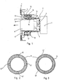
- With 1 is the front of a switch panel for a household appliance forming aperture plate designated, which in the illustrated embodiment made of a transparent material, for. B. glass.
- the diaphragm plate 1 is tinted or colored from the rear so that a transparent ring area 3 remains only around a toggle opening 2.
- the toggle opening 2 in the diaphragm plate 1 is occupied by a retractable rotary toggle 4 which is designed as a hollow cylinder and which, in its lowered position (rest position), is flush with the front of the bleno plate 1.
- the rotary toggle 4 is slidably or displaceably on a toggle shaft 5 which is operatively connected to a switching or regulating device 7 via a plug connection 6.
- a compression spring Inside the rotary toggle 4 is a compression spring, not visible, which is supported against the end of the toggle shaft 5 which ends in the rotary toggle and by means of which it is pressed by briefly tapping the rotary toggle 1 from its retracted latching position into the extended operating position, in which the Switching or regulating device 7 can be set.
- the reflector body 8 has an annular reflector chamber 10 which is open towards the diaphragm plate 1 and is formed by molding. so that the reflector body and reflector chamber are integrally formed.
- the open side of the reflector chamber 10 directed towards the rear of the diaphragm plate 1 is covered with a translucent or translucent ring body 11, which preferably consists of a prism glass or a glass ring with a prism-like surface arranged on the outside.
- a luminous element is accommodated, which consists of several individual glow lamps 12, 12 'distributed around its circumference.
- 12 ", 12" 'or consists of a glow lamp with a plurality of arc-shaped fluorescent glass bulbs 13, 13', 13 ".
- the glow lamps 12, 12 ', 12 ", 12"' are arranged so as to protrude vertically from the insulating ring body 14.
- the insulating ring body 14 also carries the electrical circuit for the glow lamps, which is designed in a known manner as a printed creation.
- a switch position indicator 16 provided with markings made of translucent material is coupled, the ring-like marking surface 17 of which is arranged between the translucent ring body 11 of the reflector chamber 10 and the rear of the diaphragm plate 1. In front of the marking surface 17 there is the transparent ring area 3 of the diaphragm plate 1.
- the switch position indicator 16 is also cylindrical or cup-shaped and designed so that the reflector body 8 takes it in with play.
Landscapes
- Engineering & Computer Science (AREA)
- Physics & Mathematics (AREA)
- General Physics & Mathematics (AREA)
- Automation & Control Theory (AREA)
- Chemical & Material Sciences (AREA)
- Combustion & Propulsion (AREA)
- Mechanical Engineering (AREA)
- General Engineering & Computer Science (AREA)
- Rotary Switch, Piano Key Switch, And Lever Switch (AREA)
- Switch Cases, Indication, And Locking (AREA)
Claims (8)
Applications Claiming Priority (2)
| Application Number | Priority Date | Filing Date | Title |
|---|---|---|---|
| DE3435291 | 1984-09-26 | ||
| DE19843435291 DE3435291A1 (de) | 1984-09-26 | 1984-09-26 | Versenkbarer drehknebel |
Publications (2)
| Publication Number | Publication Date |
|---|---|
| EP0179246A1 EP0179246A1 (fr) | 1986-04-30 |
| EP0179246B1 true EP0179246B1 (fr) | 1988-11-09 |
Family
ID=6246395
Family Applications (1)
| Application Number | Title | Priority Date | Filing Date |
|---|---|---|---|
| EP85111400A Expired EP0179246B1 (fr) | 1984-09-26 | 1985-09-10 | Bouton tournant et escamotable |
Country Status (2)
| Country | Link |
|---|---|
| EP (1) | EP0179246B1 (fr) |
| DE (2) | DE3435291A1 (fr) |
Families Citing this family (13)
| Publication number | Priority date | Publication date | Assignee | Title |
|---|---|---|---|---|
| DE3702291A1 (de) * | 1987-01-27 | 1988-08-04 | Buderus Kuechentechnik | Vorrichtung zum einstellen der schalter und regelvorrichtungen eines haushaltgeraetes |
| IT1266873B1 (it) * | 1994-07-06 | 1997-01-21 | Merloni Elettrodomestici Spa | Apparato elettrodomestico del tipo integrabile |
| US5521345A (en) * | 1994-09-30 | 1996-05-28 | Tokheim Corporation | Backlit membrane keypad |
| DE69509214T2 (de) * | 1995-03-11 | 1999-10-14 | Whirlpool Europe B.V. | Regelknopf für elektrische Hausgeräte mit leicht sehbarer, mit Zeichen versehener, Vorrichtung |
| IT237294Y1 (it) * | 1995-11-20 | 2000-09-05 | Candy Spa | Forno domestico a pannello frontale continuo |
| DE19712294C2 (de) * | 1997-03-24 | 1999-08-12 | Preh Elektro Feinmechanik | Drehwiderstand |
| FR2790843A1 (fr) * | 1999-03-08 | 2000-09-15 | Demo | Bouton de commande d'un tableau de commande(s) d'un vehicule pourvu d'un element formant loupe face a une signaletique et tableau de commande(s) correspondant |
| US6666555B2 (en) * | 2001-11-09 | 2003-12-23 | Reichert, Inc. | Ophthalmic refractor having retrofittable readout illumination |
| DE10207547A1 (de) * | 2002-02-22 | 2003-09-04 | Bsh Bosch Siemens Hausgeraete | Programmwahlschalter für Haushaltgeräte |
| CN100339529C (zh) * | 2002-03-05 | 2007-09-26 | 乐金电子(天津)电器有限公司 | 洗衣机的控制器组合结构 |
| GB0422927D0 (en) * | 2004-10-15 | 2004-11-17 | Gamesman Ltd | Push button assembly |
| US9639111B2 (en) * | 2010-12-31 | 2017-05-02 | Arcelik Anonim Sirketi | Household appliance comprising a knob the outer periphery of which is illuminated |
| CN105333460B (zh) * | 2014-07-30 | 2020-10-16 | 博西华电器(江苏)有限公司 | 灶具的操作装置及灶具 |
Family Cites Families (4)
| Publication number | Priority date | Publication date | Assignee | Title |
|---|---|---|---|---|
| DE1679226A1 (de) * | 1967-11-29 | 1971-03-25 | Neff Werke | Anzeigevorrichtung fuer den Betriebszustand an Kochherden |
| DE7517896U (de) * | 1975-06-05 | 1975-11-13 | Burger Eisenwerke Ag | Anzeigevorrichtung für Herde |
| DE2605442C3 (de) * | 1976-02-12 | 1981-07-02 | Küppersbusch AG, 4650 Gelsenkirchen | Optische Anzeigevorrichtung für mit drehbaren Betätigungsgriffen ausgestattete Einstellorgane von Haushaltgeräten |
| DE2701017C2 (de) * | 1977-01-12 | 1984-06-20 | Bosch-Siemens Hausgeräte GmbH, 7000 Stuttgart | Drehknebel für die Schalter von Haushaltgeräten |
-
1984
- 1984-09-26 DE DE19843435291 patent/DE3435291A1/de not_active Withdrawn
-
1985
- 1985-09-10 EP EP85111400A patent/EP0179246B1/fr not_active Expired
- 1985-09-10 DE DE8585111400T patent/DE3566189D1/de not_active Expired
Also Published As
| Publication number | Publication date |
|---|---|
| DE3566189D1 (en) | 1988-12-15 |
| EP0179246A1 (fr) | 1986-04-30 |
| DE3435291A1 (de) | 1986-04-03 |
Similar Documents
| Publication | Publication Date | Title |
|---|---|---|
| EP0179246B1 (fr) | Bouton tournant et escamotable | |
| EP0176817B1 (fr) | Panneau d'un commutateur, pour appareils électro-domestiques avec un bouton tournant et escamotable | |
| EP0276463B1 (fr) | Dispositif de réglage d'interrupteurs et dispositifs de réglage d'un appareil ménager | |
| DE69319450T2 (de) | Lichtleitereinrichtung zum ausschalten von zündungswilligen strassenlampen | |
| DE4224915A1 (de) | Zwerglampen | |
| DE2831174A1 (de) | Leuchtanzeige-vorrichtung | |
| DE3237589A1 (de) | Leuchttaster, insbesondere zum einbau in elektrische schalttafeln oder dergleichen | |
| DE2950550C2 (de) | Druckknopfschalter mit einer Leuchtanzeige | |
| DE3133134A1 (de) | Elektrischer schalter, insbesondere fuer kraftfahrzeuge | |
| DE3430993A1 (de) | Optische schaltstufenanzeige fuer drehwahlschalter von haushaltsgeraeten, insbesondere von herden | |
| EP0056104A1 (fr) | Lumière indicatrice | |
| DE19539081A1 (de) | Bedienmodul für elektrische Haushaltsgeräte | |
| DE20117279U1 (de) | Drucktaste für elektrische oder elektronische Bauteile | |
| DE584151C (de) | Beleuchtungseinrichtung fuer Installationsapparate | |
| DE4204499C2 (de) | Drehwahlschalter mit Schaltstellenanzeige und Beleuchtung | |
| DE2830446A1 (de) | Leuchttaste | |
| DE3508232C2 (fr) | ||
| EP0063718A1 (fr) | Lampe pour contact | |
| DE19814488A1 (de) | Funklichtdimmer für Glühlampen | |
| DE479484C (de) | Fluessigkeitsstandsanzeiger mit in der Achsrichtung des Fluessigkeitsstandglases wirkendem Beleuchtungskoerper | |
| DE1908708C3 (de) | Elektrische Handleuchte, insbesondere Warnblinkleuchte für Kraftfahrer | |
| DE543692C (de) | Elektrischer Anschlussstecker mit regelbarem Widerstand | |
| DE2643036A1 (de) | Hausnummernleuchte | |
| DE617082C (de) | Elektrische Leuchte mit eingebautem Quecksilberschalter | |
| DE2103793A1 (de) | Trinkglas |
Legal Events
| Date | Code | Title | Description |
|---|---|---|---|
| PUAI | Public reference made under article 153(3) epc to a published international application that has entered the european phase |
Free format text: ORIGINAL CODE: 0009012 |
|
| AK | Designated contracting states |
Kind code of ref document: A1 Designated state(s): DE FR GB IT |
|
| 17P | Request for examination filed |
Effective date: 19861009 |
|
| 17Q | First examination report despatched |
Effective date: 19880302 |
|
| GRAA | (expected) grant |
Free format text: ORIGINAL CODE: 0009210 |
|
| AK | Designated contracting states |
Kind code of ref document: B1 Designated state(s): DE FR GB IT |
|
| GBT | Gb: translation of ep patent filed (gb section 77(6)(a)/1977) | ||
| REF | Corresponds to: |
Ref document number: 3566189 Country of ref document: DE Date of ref document: 19881215 |
|
| ET | Fr: translation filed | ||
| ITF | It: translation for a ep patent filed | ||
| PLBE | No opposition filed within time limit |
Free format text: ORIGINAL CODE: 0009261 |
|
| STAA | Information on the status of an ep patent application or granted ep patent |
Free format text: STATUS: NO OPPOSITION FILED WITHIN TIME LIMIT |
|
| 26N | No opposition filed | ||
| PGFP | Annual fee paid to national office [announced via postgrant information from national office to epo] |
Ref country code: GB Payment date: 19900820 Year of fee payment: 6 |
|
| PGFP | Annual fee paid to national office [announced via postgrant information from national office to epo] |
Ref country code: FR Payment date: 19900906 Year of fee payment: 6 |
|
| ITTA | It: last paid annual fee | ||
| PG25 | Lapsed in a contracting state [announced via postgrant information from national office to epo] |
Ref country code: GB Effective date: 19910910 |
|
| PGFP | Annual fee paid to national office [announced via postgrant information from national office to epo] |
Ref country code: DE Payment date: 19911023 Year of fee payment: 7 |
|
| GBPC | Gb: european patent ceased through non-payment of renewal fee | ||
| PG25 | Lapsed in a contracting state [announced via postgrant information from national office to epo] |
Ref country code: FR Effective date: 19920529 |
|
| REG | Reference to a national code |
Ref country code: FR Ref legal event code: ST |
|
| PG25 | Lapsed in a contracting state [announced via postgrant information from national office to epo] |
Ref country code: DE Effective date: 19930602 |