EP0175675A2 - Chenal de coulée basculant pour le guidage de matière en fusion - Google Patents
Chenal de coulée basculant pour le guidage de matière en fusion Download PDFInfo
- Publication number
- EP0175675A2 EP0175675A2 EP85890200A EP85890200A EP0175675A2 EP 0175675 A2 EP0175675 A2 EP 0175675A2 EP 85890200 A EP85890200 A EP 85890200A EP 85890200 A EP85890200 A EP 85890200A EP 0175675 A2 EP0175675 A2 EP 0175675A2
- Authority
- EP
- European Patent Office
- Prior art keywords
- channel
- tipping
- channel part
- jet
- trough
- Prior art date
- Legal status (The legal status is an assumption and is not a legal conclusion. Google has not performed a legal analysis and makes no representation as to the accuracy of the status listed.)
- Granted
Links
Images

Classifications
-
- F—MECHANICAL ENGINEERING; LIGHTING; HEATING; WEAPONS; BLASTING
- F27—FURNACES; KILNS; OVENS; RETORTS
- F27D—DETAILS OR ACCESSORIES OF FURNACES, KILNS, OVENS, OR RETORTS, IN SO FAR AS THEY ARE OF KINDS OCCURRING IN MORE THAN ONE KIND OF FURNACE
- F27D3/00—Charging; Discharging; Manipulation of charge
- F27D3/14—Charging or discharging liquid or molten material
Definitions
- the invention relates to a tipping trough for guiding molten material, in particular mineral spinnable materials, such as slag, with a trough-shaped trough body which can be pivoted about a tipping axis by means of a swivel drive from a normal operating position to an emergency operating position and vice versa, and has spouts at opposite ends the end spouts has a point of impact for a jet of molten material.
- molten material in particular mineral spinnable materials, such as slag
- a tipping channel is known for example from DE-C - 628 234. It serves to direct the molten material hitting the tipping channel in one jet in different directions and thus into different vessels.
- the point of impact of the beam is subject to a particularly high thermal load in tipping channels.
- the impact of the jet also causes erosion of the refractory lining of the known channel at the point of impact and thus contamination of the melt by refractory material.
- the fireproof lining must be replaced at the point of impact at short intervals. This is particularly the case when the jet of molten material emerges from a metallurgical vessel approximately horizontally, since one is then forced to arrange the longitudinal axis of the tipping channel approximately transversely to the plane of the jet.
- the invention aims to avoid these disadvantages and Difficulties and the task is to create a tipping channel of the type described above, in which the point of impact of the jet has approximately the same lifespan as the rest of the trough and in the operating position, ie in the mainly used tilting position, a deflection of the pouring jet is avoided from its level.
- the trough-shaped channel body is formed by two channel parts with their longitudinal axes forming an angle 0 ⁇ Lf ⁇ 180 °, preferably an approximately right angle, the bottom of a first channel part being arranged at a lower level than the bottom of the second channel part is, the point of impact of the jet at the first channel part is provided close to the junction with the second channel part, and the vertical center plane of the first channel part is in the downward inclined normal operating position of the first channel part in the plane formed by the beam.
- a particularly simple design is characterized in that the second channel part is arranged with its longitudinal axis parallel to the tilt axis.
- both channel parts form an acute angle with their longitudinal axes with the tilt axis, preferably an angle of 45 °, the tilt axis in the region of the mouth of the first channel part is arranged in the second channel part.
- the two channel parts keep each other about the equilibrium about the equilibrium, so that the swivel drive only has to overcome the moment of inertia of the tilting channel about the tilting axis when pivoting or to hold the tilting channel securely in the different positions.
- the first channel part is preferably arranged rotated about its longitudinal axis with respect to the second channel part.
- a simple to produce embodiment is characterized in that the channel parts have a V-shaped cross section standing at the tip when the melt flows and are each formed by two side walls which are at the same angle to one another, preferably at right angles to one another, one side wall of the second gutter part lying at a higher level merges into the upper edge of a side wall of the first gutter part.
- a side wall of the second channel part which is at a higher level, merges into a wall part higher than a side wall of the first channel part.
- the side walls are preferably hollow and with provided with water cooling, which has the advantage that a solidified material layer, that is to say an insulation of the same type, is formed on the inner sides of the channel body, which makes brickwork unnecessary and prevents contamination of the molten material by foreign material.
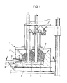
- FIG. 1 showing a section through an electric furnace, on the spout of which the tipping channel according to the invention is mounted according to a first embodiment.
- Fig. 2 shows a section along the line II-II of Fig. 1 through the furnace.
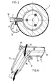
- the tipping trough according to the first embodiment is shown on an enlarged scale in an oblique view in different tilting positions.
- FIG. 5 illustrates a further embodiment of the tipping channel in a representation analogous to FIG. 3.
- melt 3 The materials 2 melted in an electric furnace 1 collect as melt 3 at the bottom 4 of the electric furnace 1. As soon as the casting level 5 reaches the lower edge 6 of the tap hole 7, melt 3 flows through the tap hole 7 from the electric furnace 1.
- melt 3 has impurities at the beginning and, for example must not get into a downstream spinner for spinning the melt.
- a tipping channel 8 is arranged below the tap hole 7, which has two channel parts 12, 13 including an approximately right angle 11 with their longitudinal axes 9, 10, the Floor 14 of the in The direction of the first channel part 12 emerging from the tap hole 7 is arranged at a lower level than the bottom 16 of the second channel part 13 arranged at right angles thereto and thus approximately at right angles to the plane 17 of the jet 15.
- the tipping channel 8 is attached to the electric furnace in such a way that the point of impact 18 of the beam lies in the first channel part 12, and so on. near the junction with the second channel part 13.
- the tipping channel 8 can be pivoted about a tilting axis 19 which is arranged parallel to the second channel part 13 and is mounted on the electric furnace 1 by means of two brackets 20 which are fastened to the furnace jacket 21.
- both channel parts 12, 13 have a V-shaped cross-section, the side walls 24, 25, 26, 27 of the channel parts 12, 13 each of two hollow at approximately right angles to each other , coolant-permeable plates are formed.
- the first channel part 12 is arranged rotated about its longitudinal axis 9 with respect to the second channel part 13, the side wall 27 of the second channel part 13 lying at a higher level merging into the upper edge 28 of the side wall 25 of the first channel part 12.
- the second side wall 26 of the second channel part 13 abuts a wall part 29 that rises above the corresponding side wall 24 of the first channel part 12.
- the first channel part 12 has a coolant supply connection 30 near its spout 23, so that the coolant flows through this channel part 12 against the direction of flow of the molten material.
- the coolant then passes into the second channel part 13, from which it exits through the outlet connection 32 arranged on the spout 31 of the second channel part 13.
- the tilt axis 19 'of the tilt channel 8' is no longer arranged parallel to the second channel part 13, but rather includes an acute angle 35 with the two longitudinal axes 9 and 10 of the channel parts 12, 13, which is approximately Is 45 °. Furthermore, the tilt axis 19 'is not horizontal, as in FIG. 1, but is arranged obliquely in space, and it extends approximately through the center of gravity of the tipping channel 8 '. With this measure, the tipping channel 8 'can be pivoted with little effort.
- the invention is not limited to the exemplary embodiments shown in the drawing, but can be modified in various ways.
- the cross section of the channel parts can be rectangular or trapezoidal.
- the angle which the two gutter parts enclose with one another is advantageously a right angle, but the two gutter parts can also enclose an angle which deviates therefrom. This angle depends on the local conditions, i.e. the available space.
Applications Claiming Priority (2)
| Application Number | Priority Date | Filing Date | Title |
|---|---|---|---|
| AT0296584A AT380467B (de) | 1984-09-18 | 1984-09-18 | Kipprinne zur fuehrung von schmelzfluessigem material |
| AT2965/84 | 1984-09-18 |
Publications (3)
| Publication Number | Publication Date |
|---|---|
| EP0175675A2 true EP0175675A2 (fr) | 1986-03-26 |
| EP0175675A3 EP0175675A3 (en) | 1986-07-23 |
| EP0175675B1 EP0175675B1 (fr) | 1988-08-17 |
Family
ID=3543192
Family Applications (1)
| Application Number | Title | Priority Date | Filing Date |
|---|---|---|---|
| EP85890200A Expired EP0175675B1 (fr) | 1984-09-18 | 1985-09-02 | Chenal de coulée basculant pour le guidage de matière en fusion |
Country Status (11)
| Country | Link |
|---|---|
| US (1) | US4678168A (fr) |
| EP (1) | EP0175675B1 (fr) |
| JP (1) | JPS6179981A (fr) |
| AT (1) | AT380467B (fr) |
| DD (1) | DD236915A5 (fr) |
| DE (1) | DE3564484D1 (fr) |
| DK (1) | DK161453C (fr) |
| FI (1) | FI78059C (fr) |
| NO (1) | NO163251C (fr) |
| SU (1) | SU1384216A3 (fr) |
| YU (1) | YU44269B (fr) |
Cited By (1)
| Publication number | Priority date | Publication date | Assignee | Title |
|---|---|---|---|---|
| EP0298074A2 (fr) * | 1987-07-03 | 1989-01-04 | VOEST-ALPINE INDUSTRIEANLAGENBAU GESELLSCHAFT m.b.H. | Installation pour la coulée séparée de la scorie métallurgique et d'un bain de fusion à partir d'un mélange fusion métallique/scorie métallurgique |
Families Citing this family (4)
| Publication number | Priority date | Publication date | Assignee | Title |
|---|---|---|---|---|
| FR2572390B1 (fr) * | 1984-10-30 | 1986-12-19 | Saint Gobain Isover | Perfectionnements a l'alimentation en materiau etirable dans les techniques de production de fibres minerales |
| US5875832A (en) * | 1996-02-21 | 1999-03-02 | Dale L. Haberny | Method and apparatus for continuous casting using a rotating cylinder |
| DE19726540C2 (de) * | 1997-06-23 | 2002-11-28 | Gft Ges Fuer Feuerfest Technik | Pralltopf |
| CN110479971B (zh) * | 2019-09-26 | 2022-07-29 | 沈阳恒泰鑫源精铸耐材有限公司 | 一种超薄型铝基流钢槽 |
Citations (6)
| Publication number | Priority date | Publication date | Assignee | Title |
|---|---|---|---|---|
| DE258613C (fr) * | ||||
| DE628234C (de) * | 1934-08-07 | 1936-04-03 | Neue Glasindustrie Ges G M B H | Vorrichtung zum Einfuellen von geschmolzenem Glas in Formen oder andere Gefaesse |
| DE1244213B (de) * | 1964-07-11 | 1967-07-13 | Babcock & Wilcox Dampfkessel | Schlackenablaufeinrichtung fuer Schlackenveredelungsanlagen |
| DE2101244A1 (en) * | 1971-01-13 | 1972-08-03 | Fried. Krupp Gmbh, 4300 Essen | Tiltable melt distributor - permitting individual slope adjustment of each channel |
| DD132717A3 (de) * | 1976-09-22 | 1978-10-25 | Guenther Petzold | Abstichrinnenanlage fuer sm-oefen,vorzugsweise fuer zweipfannenabstich |
| US4444378A (en) * | 1982-08-11 | 1984-04-24 | Reese Thurston F | Apparatus for separating slag from a molten metal |
Family Cites Families (2)
| Publication number | Priority date | Publication date | Assignee | Title |
|---|---|---|---|---|
| US1061280A (en) * | 1913-01-13 | 1913-05-13 | Edward L Ford | Ladle-runner. |
| US1881228A (en) * | 1929-04-20 | 1932-10-04 | Chester H Pape | Pouring spout |
-
1984
- 1984-09-18 AT AT0296584A patent/AT380467B/de not_active IP Right Cessation
-
1985
- 1985-09-02 EP EP85890200A patent/EP0175675B1/fr not_active Expired
- 1985-09-02 DE DE8585890200T patent/DE3564484D1/de not_active Expired
- 1985-09-10 FI FI853459A patent/FI78059C/fi not_active IP Right Cessation
- 1985-09-10 YU YU1421/85A patent/YU44269B/xx unknown
- 1985-09-13 US US06/775,536 patent/US4678168A/en not_active Expired - Fee Related
- 1985-09-13 DD DD85280598A patent/DD236915A5/de not_active IP Right Cessation
- 1985-09-17 NO NO853652A patent/NO163251C/no unknown
- 1985-09-17 SU SU853953978A patent/SU1384216A3/ru active
- 1985-09-17 DK DK421185A patent/DK161453C/da not_active IP Right Cessation
- 1985-09-18 JP JP60207727A patent/JPS6179981A/ja active Granted
Patent Citations (6)
| Publication number | Priority date | Publication date | Assignee | Title |
|---|---|---|---|---|
| DE258613C (fr) * | ||||
| DE628234C (de) * | 1934-08-07 | 1936-04-03 | Neue Glasindustrie Ges G M B H | Vorrichtung zum Einfuellen von geschmolzenem Glas in Formen oder andere Gefaesse |
| DE1244213B (de) * | 1964-07-11 | 1967-07-13 | Babcock & Wilcox Dampfkessel | Schlackenablaufeinrichtung fuer Schlackenveredelungsanlagen |
| DE2101244A1 (en) * | 1971-01-13 | 1972-08-03 | Fried. Krupp Gmbh, 4300 Essen | Tiltable melt distributor - permitting individual slope adjustment of each channel |
| DD132717A3 (de) * | 1976-09-22 | 1978-10-25 | Guenther Petzold | Abstichrinnenanlage fuer sm-oefen,vorzugsweise fuer zweipfannenabstich |
| US4444378A (en) * | 1982-08-11 | 1984-04-24 | Reese Thurston F | Apparatus for separating slag from a molten metal |
Cited By (2)
| Publication number | Priority date | Publication date | Assignee | Title |
|---|---|---|---|---|
| EP0298074A2 (fr) * | 1987-07-03 | 1989-01-04 | VOEST-ALPINE INDUSTRIEANLAGENBAU GESELLSCHAFT m.b.H. | Installation pour la coulée séparée de la scorie métallurgique et d'un bain de fusion à partir d'un mélange fusion métallique/scorie métallurgique |
| EP0298074A3 (en) * | 1987-07-03 | 1989-02-22 | Industrieanlagenbau Gesellschaft M.B.H. Voest-Alpine | Plant for separately casting metallurgical slag and metal melt from a metal-melt/metallurgical-slag mixture |
Also Published As
| Publication number | Publication date |
|---|---|
| JPS6179981A (ja) | 1986-04-23 |
| JPH0524429B2 (fr) | 1993-04-07 |
| FI78059B (fi) | 1989-02-28 |
| FI78059C (fi) | 1989-06-12 |
| NO163251B (no) | 1990-01-15 |
| EP0175675B1 (fr) | 1988-08-17 |
| FI853459L (fi) | 1986-03-19 |
| YU142185A (en) | 1988-04-30 |
| AT380467B (de) | 1986-05-26 |
| EP0175675A3 (en) | 1986-07-23 |
| DK421185D0 (da) | 1985-09-17 |
| DE3564484D1 (en) | 1988-09-22 |
| FI853459A0 (fi) | 1985-09-10 |
| US4678168A (en) | 1987-07-07 |
| DK421185A (da) | 1986-03-19 |
| NO853652L (no) | 1986-03-19 |
| ATA296584A (de) | 1985-10-15 |
| NO163251C (no) | 1990-04-25 |
| DK161453C (da) | 1992-01-06 |
| DK161453B (da) | 1991-07-08 |
| DD236915A5 (de) | 1986-06-25 |
| YU44269B (en) | 1990-04-30 |
| SU1384216A3 (ru) | 1988-03-23 |
Similar Documents
| Publication | Publication Date | Title |
|---|---|---|
| DE2634281A1 (de) | Vorrichtung zum ziehen von glasfasern | |
| EP0254909A1 (fr) | Busette de coulée réfractaire | |
| DE3019811C2 (de) | Abflußsteuerorgan für einen Schmelzofen | |
| DE2919880A1 (de) | Giessrohr | |
| DE2239283A1 (de) | Vorrichtung an einer stranggiessanlage, insbesondere an einer anlage zum kontinuierlichen stahlstranggiessen | |
| DE2013290A1 (de) | Stranggußmaschine | |
| EP0175675B1 (fr) | Chenal de coulée basculant pour le guidage de matière en fusion | |
| DE4313041A1 (de) | Gießen von Metallband | |
| DE3524372C2 (fr) | ||
| DE2738587A1 (de) | Abschirmvorrichtung fuer einen giessstrahl aus fluessigem metall | |
| EP0015251B1 (fr) | Dispositif pour récipient métallurgique avec un tube protecteur | |
| DE4032521C2 (fr) | ||
| CH631645A5 (de) | Vorrichtung zum herausziehen eines metallstranges aus der kokille einer stranggussanlage. | |
| DE2632863C2 (de) | Einrichtung zur Herstellung von großtonnagigen Metallblöcken durch Elektroschlackenumschmelzen | |
| DE1925438C3 (de) | Elektroschlacke-Umschmelzanlage | |
| DE2134099C3 (de) | Kippbare Verteilerrinne für durch eine Abstichrinne aus einem Schmelzofen zufließende Schmelze | |
| DE2816204C2 (de) | Transportbehälter fur schmelzflüssiges Metall | |
| DE19811957C2 (de) | Anordnung eines Tauchausgusses in einer Kokille zum Stranggießen von Brammen | |
| DE1945141A1 (de) | Einrichtung zum horizontalen Stranggiessen | |
| DE2055154B2 (de) | Verfahren zur kontinuierlichen Herstellung von Glasbändern und Vorrichtung zur Durchführung des Verfahrens | |
| EP0151802B1 (fr) | Dispositif pour l'introduction de métal liquide, en particulier d'acier liquide dans une coquille de coulée continue | |
| DE3612613C1 (de) | Rinne zum kontinuierlichen Raffinieren von Metallschmelzen, insbesondere von Roheisenschmelzen | |
| DE2412053C2 (de) | Vorrichtung zum Zuführen und Verteilen von Stahlschmelzen | |
| DE1558297C (de) | Vorrichtung zum unterbrechungsfreien Beschicken einer Rotations-Stranggießvorrichtung, sowie Betriebsverfahren hierfür | |
| LU82416A1 (de) | Vorrichtung und verfahren zum chargenweisen giessen in einer stahlstranggiesserei |
Legal Events
| Date | Code | Title | Description |
|---|---|---|---|
| PUAI | Public reference made under article 153(3) epc to a published international application that has entered the european phase |
Free format text: ORIGINAL CODE: 0009012 |
|
| AK | Designated contracting states |
Kind code of ref document: A2 Designated state(s): BE CH DE FR GB IT LI LU NL SE |
|
| PUAL | Search report despatched |
Free format text: ORIGINAL CODE: 0009013 |
|
| AK | Designated contracting states |
Kind code of ref document: A3 Designated state(s): BE CH DE FR GB IT LI LU NL SE |
|
| 17P | Request for examination filed |
Effective date: 19861229 |
|
| 17Q | First examination report despatched |
Effective date: 19880126 |
|
| GRAA | (expected) grant |
Free format text: ORIGINAL CODE: 0009210 |
|
| AK | Designated contracting states |
Kind code of ref document: B1 Designated state(s): BE CH DE FR GB IT LI LU NL SE |
|
| PG25 | Lapsed in a contracting state [announced via postgrant information from national office to epo] |
Ref country code: IT Free format text: LAPSE BECAUSE OF FAILURE TO SUBMIT A TRANSLATION OF THE DESCRIPTION OR TO PAY THE FEE WITHIN THE PRESCRIBED TIME-LIMIT;WARNING: LAPSES OF ITALIAN PATENTS WITH EFFECTIVE DATE BEFORE 2007 MAY HAVE OCCURRED AT ANY TIME BEFORE 2007. THE CORRECT EFFECTIVE DATE MAY BE DIFFERENT FROM THE ONE RECORDED. Effective date: 19880817 Ref country code: FR Free format text: THE PATENT HAS BEEN ANNULLED BY A DECISION OF A NATIONAL AUTHORITY Effective date: 19880817 Ref country code: BE Effective date: 19880817 Ref country code: NL Effective date: 19880817 |
|
| REF | Corresponds to: |
Ref document number: 3564484 Country of ref document: DE Date of ref document: 19880922 |
|
| GBT | Gb: translation of ep patent filed (gb section 77(6)(a)/1977) | ||
| EN | Fr: translation not filed | ||
| NLV1 | Nl: lapsed or annulled due to failure to fulfill the requirements of art. 29p and 29m of the patents act | ||
| PLBE | No opposition filed within time limit |
Free format text: ORIGINAL CODE: 0009261 |
|
| STAA | Information on the status of an ep patent application or granted ep patent |
Free format text: STATUS: NO OPPOSITION FILED WITHIN TIME LIMIT |
|
| 26N | No opposition filed | ||
| REG | Reference to a national code |
Ref country code: GB Ref legal event code: 732 |
|
| REG | Reference to a national code |
Ref country code: CH Ref legal event code: PUE Owner name: VOEST-ALPINE INDUSTRIEANLAGENBAU GESELLSCHAFT MBH |
|
| PGFP | Annual fee paid to national office [announced via postgrant information from national office to epo] |
Ref country code: DE Payment date: 19930811 Year of fee payment: 9 |
|
| PGFP | Annual fee paid to national office [announced via postgrant information from national office to epo] |
Ref country code: CH Payment date: 19930812 Year of fee payment: 9 |
|
| PGFP | Annual fee paid to national office [announced via postgrant information from national office to epo] |
Ref country code: GB Payment date: 19930816 Year of fee payment: 9 |
|
| PGFP | Annual fee paid to national office [announced via postgrant information from national office to epo] |
Ref country code: SE Payment date: 19930817 Year of fee payment: 9 |
|
| PGFP | Annual fee paid to national office [announced via postgrant information from national office to epo] |
Ref country code: LU Payment date: 19930819 Year of fee payment: 9 |
|
| EPTA | Lu: last paid annual fee | ||
| PG25 | Lapsed in a contracting state [announced via postgrant information from national office to epo] |
Ref country code: LU Free format text: LAPSE BECAUSE OF NON-PAYMENT OF DUE FEES Effective date: 19940902 Ref country code: GB Effective date: 19940902 |
|
| PG25 | Lapsed in a contracting state [announced via postgrant information from national office to epo] |
Ref country code: SE Effective date: 19940903 |
|
| PG25 | Lapsed in a contracting state [announced via postgrant information from national office to epo] |
Ref country code: LI Effective date: 19940930 Ref country code: CH Effective date: 19940930 |
|
| EAL | Se: european patent in force in sweden |
Ref document number: 85890200.0 |
|
| GBPC | Gb: european patent ceased through non-payment of renewal fee |
Effective date: 19940902 |
|
| REG | Reference to a national code |
Ref country code: CH Ref legal event code: PL |
|
| PG25 | Lapsed in a contracting state [announced via postgrant information from national office to epo] |
Ref country code: DE Effective date: 19950601 |
|
| EUG | Se: european patent has lapsed |
Ref document number: 85890200.0 |