EP0175675A2 - Tilting channel for guiding a molten material - Google Patents
Tilting channel for guiding a molten material Download PDFInfo
- Publication number
- EP0175675A2 EP0175675A2 EP85890200A EP85890200A EP0175675A2 EP 0175675 A2 EP0175675 A2 EP 0175675A2 EP 85890200 A EP85890200 A EP 85890200A EP 85890200 A EP85890200 A EP 85890200A EP 0175675 A2 EP0175675 A2 EP 0175675A2
- Authority
- EP
- European Patent Office
- Prior art keywords
- channel
- tipping
- channel part
- jet
- trough
- Prior art date
- Legal status (The legal status is an assumption and is not a legal conclusion. Google has not performed a legal analysis and makes no representation as to the accuracy of the status listed.)
- Granted
Links
Images

Classifications
-
- F—MECHANICAL ENGINEERING; LIGHTING; HEATING; WEAPONS; BLASTING
- F27—FURNACES; KILNS; OVENS; RETORTS
- F27D—DETAILS OR ACCESSORIES OF FURNACES, KILNS, OVENS, OR RETORTS, IN SO FAR AS THEY ARE OF KINDS OCCURRING IN MORE THAN ONE KIND OF FURNACE
- F27D3/00—Charging; Discharging; Manipulation of charge
- F27D3/14—Charging or discharging liquid or molten material
Definitions
- the invention relates to a tipping trough for guiding molten material, in particular mineral spinnable materials, such as slag, with a trough-shaped trough body which can be pivoted about a tipping axis by means of a swivel drive from a normal operating position to an emergency operating position and vice versa, and has spouts at opposite ends the end spouts has a point of impact for a jet of molten material.
- molten material in particular mineral spinnable materials, such as slag
- a tipping channel is known for example from DE-C - 628 234. It serves to direct the molten material hitting the tipping channel in one jet in different directions and thus into different vessels.
- the point of impact of the beam is subject to a particularly high thermal load in tipping channels.
- the impact of the jet also causes erosion of the refractory lining of the known channel at the point of impact and thus contamination of the melt by refractory material.
- the fireproof lining must be replaced at the point of impact at short intervals. This is particularly the case when the jet of molten material emerges from a metallurgical vessel approximately horizontally, since one is then forced to arrange the longitudinal axis of the tipping channel approximately transversely to the plane of the jet.
- the invention aims to avoid these disadvantages and Difficulties and the task is to create a tipping channel of the type described above, in which the point of impact of the jet has approximately the same lifespan as the rest of the trough and in the operating position, ie in the mainly used tilting position, a deflection of the pouring jet is avoided from its level.
- the trough-shaped channel body is formed by two channel parts with their longitudinal axes forming an angle 0 ⁇ Lf ⁇ 180 °, preferably an approximately right angle, the bottom of a first channel part being arranged at a lower level than the bottom of the second channel part is, the point of impact of the jet at the first channel part is provided close to the junction with the second channel part, and the vertical center plane of the first channel part is in the downward inclined normal operating position of the first channel part in the plane formed by the beam.
- a particularly simple design is characterized in that the second channel part is arranged with its longitudinal axis parallel to the tilt axis.
- both channel parts form an acute angle with their longitudinal axes with the tilt axis, preferably an angle of 45 °, the tilt axis in the region of the mouth of the first channel part is arranged in the second channel part.
- the two channel parts keep each other about the equilibrium about the equilibrium, so that the swivel drive only has to overcome the moment of inertia of the tilting channel about the tilting axis when pivoting or to hold the tilting channel securely in the different positions.
- the first channel part is preferably arranged rotated about its longitudinal axis with respect to the second channel part.
- a simple to produce embodiment is characterized in that the channel parts have a V-shaped cross section standing at the tip when the melt flows and are each formed by two side walls which are at the same angle to one another, preferably at right angles to one another, one side wall of the second gutter part lying at a higher level merges into the upper edge of a side wall of the first gutter part.
- a side wall of the second channel part which is at a higher level, merges into a wall part higher than a side wall of the first channel part.
- the side walls are preferably hollow and with provided with water cooling, which has the advantage that a solidified material layer, that is to say an insulation of the same type, is formed on the inner sides of the channel body, which makes brickwork unnecessary and prevents contamination of the molten material by foreign material.
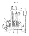
- FIG. 1 showing a section through an electric furnace, on the spout of which the tipping channel according to the invention is mounted according to a first embodiment.
- Fig. 2 shows a section along the line II-II of Fig. 1 through the furnace.
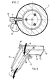
- the tipping trough according to the first embodiment is shown on an enlarged scale in an oblique view in different tilting positions.
- FIG. 5 illustrates a further embodiment of the tipping channel in a representation analogous to FIG. 3.
- melt 3 The materials 2 melted in an electric furnace 1 collect as melt 3 at the bottom 4 of the electric furnace 1. As soon as the casting level 5 reaches the lower edge 6 of the tap hole 7, melt 3 flows through the tap hole 7 from the electric furnace 1.
- melt 3 has impurities at the beginning and, for example must not get into a downstream spinner for spinning the melt.
- a tipping channel 8 is arranged below the tap hole 7, which has two channel parts 12, 13 including an approximately right angle 11 with their longitudinal axes 9, 10, the Floor 14 of the in The direction of the first channel part 12 emerging from the tap hole 7 is arranged at a lower level than the bottom 16 of the second channel part 13 arranged at right angles thereto and thus approximately at right angles to the plane 17 of the jet 15.
- the tipping channel 8 is attached to the electric furnace in such a way that the point of impact 18 of the beam lies in the first channel part 12, and so on. near the junction with the second channel part 13.
- the tipping channel 8 can be pivoted about a tilting axis 19 which is arranged parallel to the second channel part 13 and is mounted on the electric furnace 1 by means of two brackets 20 which are fastened to the furnace jacket 21.
- both channel parts 12, 13 have a V-shaped cross-section, the side walls 24, 25, 26, 27 of the channel parts 12, 13 each of two hollow at approximately right angles to each other , coolant-permeable plates are formed.
- the first channel part 12 is arranged rotated about its longitudinal axis 9 with respect to the second channel part 13, the side wall 27 of the second channel part 13 lying at a higher level merging into the upper edge 28 of the side wall 25 of the first channel part 12.
- the second side wall 26 of the second channel part 13 abuts a wall part 29 that rises above the corresponding side wall 24 of the first channel part 12.
- the first channel part 12 has a coolant supply connection 30 near its spout 23, so that the coolant flows through this channel part 12 against the direction of flow of the molten material.
- the coolant then passes into the second channel part 13, from which it exits through the outlet connection 32 arranged on the spout 31 of the second channel part 13.
- the tilt axis 19 'of the tilt channel 8' is no longer arranged parallel to the second channel part 13, but rather includes an acute angle 35 with the two longitudinal axes 9 and 10 of the channel parts 12, 13, which is approximately Is 45 °. Furthermore, the tilt axis 19 'is not horizontal, as in FIG. 1, but is arranged obliquely in space, and it extends approximately through the center of gravity of the tipping channel 8 '. With this measure, the tipping channel 8 'can be pivoted with little effort.
- the invention is not limited to the exemplary embodiments shown in the drawing, but can be modified in various ways.
- the cross section of the channel parts can be rectangular or trapezoidal.
- the angle which the two gutter parts enclose with one another is advantageously a right angle, but the two gutter parts can also enclose an angle which deviates therefrom. This angle depends on the local conditions, i.e. the available space.
Abstract
Bei einer Kipprinne (8) zur Führung von schmelzflüssigem Material ist der Rinnenkörper (12, 13) um eine Kippachse (19) aus einer Normalbetriebs- (A) in eine Notbetriebsposition und umgekehrt schwenkbar und weist eine zwischen zwei an gegenüberliegenden Enden vorgesehenen Ausgüssen (23, 31) angeordnete Auftreffstelle (18) für einen Materialstrahl (15) auf. Um bei einer derartigen Kipprimne (8) einen vorzeitigen Verschleiß an der Auftreffstelle (18) des Strahles (15) und in der Normalbetriebsposition (A) ein Umlenken des Gießstrahles (15) zu vermeiden. ist der Rinnenkörper (8) von zwei einen Winkel 0 < φ < 180° einschließenden Rinnenteilen (12, 13) gebildet, wobei der Boden (14) des ersten Rinnenteiles (12) gegenüber dem Boden (16) des zweiten Rinnenteiles (13) niveaumäßig tiefer liegt, die Auftreffstelle (18) am ersten Rinnenteil (12) nahe der Einmündung in den zweiten Rinnenteil (13) vorgesehen ist und die vertikale Mittelebene (33) des ersten Rinnenteiles (12) in der Ebene (17) des Strahles (15) liegt.In the case of a tipping trough (8) for guiding molten material, the trough body (12, 13) can be pivoted about a tilting axis (19) from a normal operating position (A) to an emergency operating position and vice versa and has a spout (23) provided between two opposite ends , 31) arranged impact point (18) for a material jet (15). In order to avoid premature wear at the point of impact (18) of the jet (15) and in the normal operating position (A) of the pouring jet (15) in the case of such a tilting rim (8). The channel body (8) is formed by two channel parts (12, 13) enclosing an angle 0 <φ <180 °, the bottom (14) of the first channel part (12) being level with respect to the bottom (16) of the second channel part (13) is lower, the impact point (18) is provided on the first channel part (12) near the junction with the second channel part (13) and the vertical center plane (33) of the first channel part (12) in the plane (17) of the jet (15) lies.
Description
Die Erfindung betrifft eine Kipprinne zur Führung von schmelzflüssigem Material, insbesondere von mineralischen verspinnbaren Stoffen, wie Schlacke, mit einem um eine Kippachse mittels eines Schwenkantriebes aus einer Normalbetriebs- in eine Notbetriebsposition und umgekehrt schwenkbaren, an gegenüberliegenden Enden mit Ausgüssen versehenen muldenförmigen Rinnenkörper, der zwischen den endseitigen Ausgüssen eine Auftreffstelle für einen Strahl schmelzflüssigen Materials aufweist.The invention relates to a tipping trough for guiding molten material, in particular mineral spinnable materials, such as slag, with a trough-shaped trough body which can be pivoted about a tipping axis by means of a swivel drive from a normal operating position to an emergency operating position and vice versa, and has spouts at opposite ends the end spouts has a point of impact for a jet of molten material.
Eine Kipprinne ist beispielsweise aus der DE-C - 628 234 bekannt. Sie dient dazu, das in einem Strahl auf die Kipprinne auftreffende schmelzflüssige Material wahlweise in verschiedene Richtungen und damit in unterschiedliche Gefäße zu leiten. Die Auftreffstelle des Strahles ist bei Kipprinnen einer besonders hohen thermischen Belastung ausgesetzt. Durch den auftreffenden Strahl kommt es an der Auftreffstelle weiters zu Erosionserscheinungen der feuerfesten Auskleidung der bekannten Rinne und damit zu einer Verschmutzung der Schmelze durch Feuerfestmaterial. Die feuerfeste Auskleidung muß an der Auftreffstelle in kurzen Abständen erneuert werden. Dies ist insbesondere dann der Fall, wenn der Strahl des schmelzflüssigen Materials aus einem metallurgischen Gefäß etwa horizontal austritt, da man dann gezwungen ist, die Längsachse der Kipprinne etwa quer zur Ebene des Strahles anzuordnen. In diesem Fall tritt an der Auftreffstelle des Strahles zusätzlich eine Umlenkung des schmelzflüssigen Materials um etwa 90° aus der Ebene des Strahles heraus auf, wodurch die Auftreffstelle besonders hoch belastet ist und die Kipprinne dementsprechend oft neu zugestellt werden muß.A tipping channel is known for example from DE-C - 628 234. It serves to direct the molten material hitting the tipping channel in one jet in different directions and thus into different vessels. The point of impact of the beam is subject to a particularly high thermal load in tipping channels. The impact of the jet also causes erosion of the refractory lining of the known channel at the point of impact and thus contamination of the melt by refractory material. The fireproof lining must be replaced at the point of impact at short intervals. This is particularly the case when the jet of molten material emerges from a metallurgical vessel approximately horizontally, since one is then forced to arrange the longitudinal axis of the tipping channel approximately transversely to the plane of the jet. In this case, a deflection of the molten material occurs at the point of impact of the jet by about 90 ° out of the plane of the jet, which places a particularly high load on the point of impact and accordingly the tipping channel often has to be readjusted accordingly.
Die Erfindung bezweckt die Vermeidung dieser Nachteile und Schwierigkeiten und stellt sich die Aufgabe, eine Kipprinne der eingangs beschriebenen Art zu schaffen, bei der die Auftreffstelle des Strahles eine etwa gleich hohe Lebensdauer aufweist wie die übrige Rinne und bei der in der Betriebsposition, d.h. in der hauptsächlich verwendeten Kipposition, eine Umlenkung des Gießstrahles aus seiner Ebene heraus vermieden wird.The invention aims to avoid these disadvantages and Difficulties and the task is to create a tipping channel of the type described above, in which the point of impact of the jet has approximately the same lifespan as the rest of the trough and in the operating position, ie in the mainly used tilting position, a deflection of the pouring jet is avoided from its level.
Diese Aufgabe wird erfindungsgemäß dadurch gelöst, daß der muldenförmige Rinnenkörper von zwei mit ihren Längsachsen einen Winkel 0<Lf<180°, vorzugsweise einen etwa rechten Winkel einschließenden Rinnenteilen gebildet ist, wobei der Boden eines ersten Rinnenteiles gegenüber dem Boden des zweiten Rinnenteiles niveaumäßig tieferliegend engeordnet ist, die Auftreffstelle des Strahles am ersten Rinnenteil nahe bei der Einmündung in den zweiten Rinnenteil vorgesehen ist, und die vertikale Mittelebene des ersten Rinnenteiles bei abwärts geneigter Normalbetriebsposition des ersten Rinnenteiles in der vom Strahl gebildeten Ebene liegt.This object is achieved in that the trough-shaped channel body is formed by two channel parts with their longitudinal axes forming an angle 0 <Lf <180 °, preferably an approximately right angle, the bottom of a first channel part being arranged at a lower level than the bottom of the second channel part is, the point of impact of the jet at the first channel part is provided close to the junction with the second channel part, and the vertical center plane of the first channel part is in the downward inclined normal operating position of the first channel part in the plane formed by the beam.
Durch die winkelförmige Ausbildung des Rinnenkörpers ist es möglich, einen der Rinnenteile des Rinnenkörpers, u.zw. jenen, der beim Normalbetrieb der Kipprinne durchströmt wird, in der Ebene des Strahles schmelzflüssigen Materials anzuordnen, so daß eine Umlenkung des Strahles aus seiner Ebene heraus und damit Erosionserscheinungen weitgehend vermieden werden. Durch Anordnung der Auftreffstelle am niveaumäßig tieferen Boden eines der Rinnenteile befindet sich nach Kippen der Rinne in Notbetriebsposition an der Auftreffstelle ein Sumpf schmelzflüssigen Materials, in den der Strahl trifft, wodurch der Strahl nicht auf einer Rinnenwand auftrifft und Erosionserscheinungen auch in dieser Position der Kipprinne weitgehend vermieden werden.Due to the angular design of the channel body, it is possible to one of the channel parts of the channel body, etc. to arrange that in the plane of the jet of molten material through which the tipping channel flows during normal operation, so that a deflection of the jet out of its plane and thus erosion phenomena are largely avoided. By arranging the impact point on the level-deep bottom of one of the channel parts, after tipping the channel in the emergency operating position, there is a sump of molten material at the point of impact into which the jet hits, as a result of which the jet does not strike a channel wall and largely shows signs of erosion even in this position of the tilting channel be avoided.
Eine konstruktiv besonders einfache Ausführungsform ist dadurch gekennzeichnet, daß der zweite Rinnenteil mit seiner Längsachse parallel zur Kippachse angeordnet ist.A particularly simple design is characterized in that the second channel part is arranged with its longitudinal axis parallel to the tilt axis.
Eine weitere bevorzugte Ausführungsform, bei der der Schwenkantrieb im wesentlichen keine Hubarbeit zu leisten hat, ist dadurch gekennzeichnet, daß beide Rinnenteile mit ihren Längsachsen mit der Kippachse einen spitzen Winkel einschließen, vorzugsweise einen Winkel von 45°, wobei die Kippachse im Bereich der Einmündung des ersten Rinnenteiles in den zweiten Rinnenteil angeordnet ist. Die beiden Rinnenteile halten einander um die Kippachse etwa das Gleichgewicht, so daß der Schwenkantrieb beim Verschwenken lediglich das Trägheitsmoment der Kipprinne um die Kippachse zu überwinden bzw. die Kipprinne in den unterschiedlichen Stellungen sicher zu halten hat.Another preferred embodiment, in which the pivot drive has essentially no lifting work, is characterized in that both channel parts form an acute angle with their longitudinal axes with the tilt axis, preferably an angle of 45 °, the tilt axis in the region of the mouth of the first channel part is arranged in the second channel part. The two channel parts keep each other about the equilibrium about the equilibrium, so that the swivel drive only has to overcome the moment of inertia of the tilting channel about the tilting axis when pivoting or to hold the tilting channel securely in the different positions.
Vorzugsweise ist der erste Rinnenteil um seine Längsachse gegenüber dem zweiten Rinnenteil verdreht angeordnet.The first channel part is preferably arranged rotated about its longitudinal axis with respect to the second channel part.
Eine einfach herzustellende Ausführungsform ist dadurch gekennzeichnet, daß die Rinnenteile einen V-förmigen, bei Schmelzendurchfluß auf der Spitze stehenden Querschnitt aufweisen und jeweils von zwei im gleichen Winkel zueinander stehenden Seitenwänden, vorzugsweise im rechten Winkel zueinander stehenden Seitenwänden, gebildet sind, wobei eine Seitenwand des niveaumäßig höherliegenden zweiten Rinnenteiles in die Oberkante einer Seitenwand des ersten Rinnenteiles übergeht.A simple to produce embodiment is characterized in that the channel parts have a V-shaped cross section standing at the tip when the melt flows and are each formed by two side walls which are at the same angle to one another, preferably at right angles to one another, one side wall of the second gutter part lying at a higher level merges into the upper edge of a side wall of the first gutter part.
Um ein Herausspritzen des schmelzflüssigen Materials aus der Kipprinne in Notbetriebsposition zu vermeiden, geht eine Seitenwand des niveaumäßig höherliegenden zweiten Rinnenteiles in einen eine Seitenwand des ersten Rinnenteiles überhöhenden Wandteil über.In order to prevent the molten material from splashing out of the tipping channel in the emergency operating position, a side wall of the second channel part, which is at a higher level, merges into a wall part higher than a side wall of the first channel part.
Vorzugsweise sind die Seitenwände hohl ausgebildet und mit einer Wasserkühlung versehen, wodurch sich der Vorteil ergibt, daß sich an den Innenseiten des Rinnenkörpers eine erstarrte Materialschicht, d.h. eine artgleiche Isolierung bildet, die eine Ausmauerung erübrigt und eine Verschmutzung des schmelzflüssigen Materials durch Fremdmaterial verhindert.The side walls are preferably hollow and with provided with water cooling, which has the advantage that a solidified material layer, that is to say an insulation of the same type, is formed on the inner sides of the channel body, which makes brickwork unnecessary and prevents contamination of the molten material by foreign material.
Die Erfindung ist nachfolgend anhand der Zeichnung an zwei Ausführungsbeispielen näher erläutert, wobei Fig. l einen Schnitt durch einen Elektroofen, an dessen Ausguß die erfindungsgemäße Kipprinne gemäß einer ersten Ausführungsform montiert ist, zeigt. Fig. 2 stellt einen entlang der Linie II-II der Fig. 1 geführten Schnitt durch den Ofen dar. In den Fig. 3 und 4 ist die Kipprinne gemäß der ersten Ausführungsform im vergrößerten Maßstab in Schrägrißdarstellung in unterschiedlichen Kippositionen gezeigt. Fig. 5 veranschaulicht in zu Fig. 3 analoger Darstellung eine weitere Ausführungsform der Kipprinne.The invention is explained in more detail below with reference to the drawing using two exemplary embodiments, FIG. 1 showing a section through an electric furnace, on the spout of which the tipping channel according to the invention is mounted according to a first embodiment. Fig. 2 shows a section along the line II-II of Fig. 1 through the furnace. In Figs. 3 and 4, the tipping trough according to the first embodiment is shown on an enlarged scale in an oblique view in different tilting positions. FIG. 5 illustrates a further embodiment of the tipping channel in a representation analogous to FIG. 3.
Die in einem Elektroofen 1 geschmolzenen Materialien 2 sammeln sich als Schmelze 3 am Boden 4 des Elektroofens 1. Sobald der Gießspiegel 5 die Unterkante 6 des Abstichloches 7 erreicht, strömt Schmelze 3 durch das Abstichloch 7 aus dem Elektroofen 1. Hierbei besteht das Problem, die zu Beginn aus dem Abstichloch 7 austretende Schmelze 3 in einen Notauffangbehälter zu leiten, da die Schmelze 3 zu Beginn Verunreinigungen aufweist und z.B. nicht in einen nachgeordneten Spinner zum Verspinnen der Schmelze gelangen darf.The
Um die wahlweise Führung des schmelzflüssigen Materials in einen Notauffangbehälter oder zur weiteren regulären Verwertung zu ermöglichen, ist unterhalb des Abstichloches 7 eine Kipprinne 8 angeordnet, die zwei mit ihren Längsachsen 9, 10 einen etwa rechten Winkel 11 einschließende Rinnenteile 12, 13 aufweist, wobei der Boden 14 des in Richtung des aus dem Abstichloch 7 austretenden Strahles 15 verlaufenden ersten Rinnenteiles 12 gegenüber dem Boden 16 des rechtwinkelig dazu und damit etwa rechtwinkelig zur Ebene 17 des Strahles 15 angeordneten zweiten Rinnenteiles 13 niveaumäßig tieferliegend angeordnet ist. Die Kipprinne 8 ist am Elektroofen derart befestigt, daß die Auftreffstelle 18 des Strahles im ersten Rinnenteil 12 liegt, u.zw. nahe der Einmündung in den zweiten Rinnenteil 13.In order to enable the optional guiding of the molten material into an emergency collection container or for further regular recycling, a
Die Kipprinne 8 ist um eine Kippachse 19 schwenkbar, die parallel zum zweiten Rinnenteil 13 angeordnet ist und mittels zweier Konsolen 20, die am Ofenmantel 21 befestigt sind, am Elektroofen 1 gelagert. Zum Schwenken der Kipprinne dient ein Schwenkantrieb 22, der als Druckmittelzylinder ausgebildet ist und einerseits nahe beim Ausguß 23 des ersten Rinnenteiles 12 und andererseits am Ofenmantel 21 angelenkt ist.The tipping
Wie aus den Fig. 3 und 4 ersichtlich ist, weisen beide Rinnenteile 12, 13 einen V-förmigen Querschnitt auf, wobei die Seitenwände 24, 25, 26, 27 der Rinnenteile 12, 13 von jeweils zwei im etwa rechten Winkel zueinander stehenden, hohlen, kühlmitteldurchflossenen Platten gebildet sind. Der erste Rinnenteil 12 ist um seine Längsachse 9 gegenüber dem zweiten Rinnenteil 13 verdreht angeordnet, wobei die Seitenwand 27 des niveaumäßig höherliegenden zweiten Rinnenteiles 13 in die Oberkante 28 der Seitenwand 25 des ersten Rinnenteiles 12 übergeht. Die zweite Seitenwand 26 des zweiten Rinnenteiles 13 stößt an einen, die entsprechende Seitenwand 24 des ersten Rinnenteiles 12 überhöhenden Wandteil 29.As can be seen from FIGS. 3 and 4, both
Der erste Rinnenteil 12 weist nahe bei seinem Ausguß 23 einen Kühlmittelzuführstutzen 30 auf, so daß das Kühlmittel diesen Rinnenteil 12 entgegen der Strömungsrichtung des schmelzflüssigen Materials durchströmt. Das Kühlmittel gelangt anschließend in den zweiten Rinnenteil 13, von dem es durch den am Ausguß 31 des zweiten Rinnenteiles 13 angeordneten Austrittsstutzen 32 austritt.The
Die Funktion der Kipprinne ist folgende:
- In Normalbetriebsposition A, die in den Fig. 1, 2 und 3 dargestellt ist, ergießt sich der
Strahl 15 in denersten Rinnenteil 12, wobei der Strahl aus seinerEbene 17 nicht ausgelenkt wird, da, wie aus Fig. 3 ersichtlich, dievertikale Mittelebene 33 desersten Rinnenteiles 12, bei in abwärts geneigter Stellung dieses Rinnenteiles (also in Normalbetriebsposition A), in der vomStrahl 15gebildeten Ebene 17 liegt. In Notbetriebsposition B, die in Fig. 4 dargestellt ist, und die dann eingenommen werden muß, wenn das schmelzflüssige Material nicht zu der demAusguß 23 des ersten Rinnenteiles anschließenden Einrichtung, beispielsweise einem Spinner, gelangen soll, - also bei Betriebsbeginn (verunreinigte Schmelze) oder bei Störungen des Elektroofens 1 oder des Spinners -, liegt dieAuftreffstelle 18 desGießstrahles 15 nach wie vor imersten Rinnenteil 12, so wie bei in Normalbetriebsposition Abefindlicher Kipprinne 8. Der in Notbetriebsposition B aufwärts gerichteteerste Rinnenteil 12 bedingt jedoch eine Sumpfbildung über derAuftreffstelle 18, und das schmelzflüssige Material gelangt erst nach Eintritt in den Sumpf in denzweiten Rinnenteil 13, der das schmelzflüssige Material zu einemNotauffangbehälter 34 führt.
- In normal operating position A, which is shown in FIGS. 1, 2 and 3, the
jet 15 pours into thefirst channel part 12, the jet not being deflected from itsplane 17, since, as can be seen from FIG. 3, thevertical Center plane 33 of thefirst channel part 12, in the downwardly inclined position of this channel part (ie in normal operating position A), lies in theplane 17 formed by thejet 15. In emergency operating position B, which is shown in Fig. 4, and which must be taken if the molten material should not reach the device, for example a spinner, which adjoins thespout 23 of the first channel part, ie at the start of operation (contaminated melt) or in the event of malfunctions in the electric furnace 1 or the spinner -, theimpact point 18 of thepouring jet 15 is still in thefirst channel part 12, as is the case with the tippingchannel 8 located in the normal operating position A, but thefirst channel part 12 directed upwards in the emergency operating position B causes sump formation theimpact point 18, and the molten material only reaches thesecond channel part 13 after entering the sump, which leads the molten material to anemergency collecting container 34.
Gemäß der in Fig. 5 dargestellten Ausführungsform ist die Kippachse 19' der Kipprinne 8'nicht mehr parallel zum zweiten Rinnenteil 13 angeordnet, sondern sie schließt mit den beiden Längsachsen 9 und 10 der Rinnenteile 12, 13 jeweils einen spitzen Winkel 35 ein, der etwa 45° beträgt. Die Kippachse 19' ist weiters nicht horizontal wie in Fig. l, sondern schräg im Raum liegend angeordnet, und sie erstreckt sich etwa durch den Schwerpunkt der Kipprinne 8'. Durch diese Maßnahme ist die Kipprinne 8' mit geringem Kraftaufwand verschwenkbar.According to the embodiment shown in FIG. 5, the tilt axis 19 'of the tilt channel 8' is no longer arranged parallel to the
Die Erfindung beschränkt sich nicht auf die in der Zeichnung dargestellten Ausführungsbeispiele, sondern ist in verschiedener Hinsicht modifizierbar. Der Querschnitt der Rinnenteile kann rechteckförmig oder trapezförmig gestaltet sein. Der Winkel, den die beiden Rinnenteile miteinander einschließen, ist vorteilhaft ein rechter Winkel, jedoch können die beiden Rinnenteile auch einen davon abweichenden Winkel einschließen. Dieser Winkel richtet sich nach den örtlichen Gegebenheiten, d.h. dem zur Verfügung stehenden Platz.The invention is not limited to the exemplary embodiments shown in the drawing, but can be modified in various ways. The cross section of the channel parts can be rectangular or trapezoidal. The angle which the two gutter parts enclose with one another is advantageously a right angle, but the two gutter parts can also enclose an angle which deviates therefrom. This angle depends on the local conditions, i.e. the available space.
Claims (7)
Applications Claiming Priority (2)
| Application Number | Priority Date | Filing Date | Title |
|---|---|---|---|
| AT2965/84 | 1984-09-18 | ||
| AT0296584A AT380467B (en) | 1984-09-18 | 1984-09-18 | TIP PRINTER FOR GUIDING MELT LIQUID MATERIAL |
Publications (3)
| Publication Number | Publication Date |
|---|---|
| EP0175675A2 true EP0175675A2 (en) | 1986-03-26 |
| EP0175675A3 EP0175675A3 (en) | 1986-07-23 |
| EP0175675B1 EP0175675B1 (en) | 1988-08-17 |
Family
ID=3543192
Family Applications (1)
| Application Number | Title | Priority Date | Filing Date |
|---|---|---|---|
| EP85890200A Expired EP0175675B1 (en) | 1984-09-18 | 1985-09-02 | Tilting channel for guiding a molten material |
Country Status (11)
| Country | Link |
|---|---|
| US (1) | US4678168A (en) |
| EP (1) | EP0175675B1 (en) |
| JP (1) | JPS6179981A (en) |
| AT (1) | AT380467B (en) |
| DD (1) | DD236915A5 (en) |
| DE (1) | DE3564484D1 (en) |
| DK (1) | DK161453C (en) |
| FI (1) | FI78059C (en) |
| NO (1) | NO163251C (en) |
| SU (1) | SU1384216A3 (en) |
| YU (1) | YU44269B (en) |
Cited By (1)
| Publication number | Priority date | Publication date | Assignee | Title |
|---|---|---|---|---|
| EP0298074A2 (en) * | 1987-07-03 | 1989-01-04 | VOEST-ALPINE INDUSTRIEANLAGENBAU GESELLSCHAFT m.b.H. | Plant for separately casting metallurgical slag and metal melt from a metal-melt/metallurgical-slag mixture |
Families Citing this family (4)
| Publication number | Priority date | Publication date | Assignee | Title |
|---|---|---|---|---|
| FR2572390B1 (en) * | 1984-10-30 | 1986-12-19 | Saint Gobain Isover | IMPROVEMENTS IN SUPPLYING STRETCHABLE MATERIAL IN MINERAL FIBER PRODUCTION TECHNIQUES |
| US5875832A (en) * | 1996-02-21 | 1999-03-02 | Dale L. Haberny | Method and apparatus for continuous casting using a rotating cylinder |
| DE19726540C2 (en) * | 1997-06-23 | 2002-11-28 | Gft Ges Fuer Feuerfest Technik | impact absorber |
| CN110479971B (en) * | 2019-09-26 | 2022-07-29 | 沈阳恒泰鑫源精铸耐材有限公司 | Ultra-thin type aluminium-based steel runner |
Citations (6)
| Publication number | Priority date | Publication date | Assignee | Title |
|---|---|---|---|---|
| DE258613C (en) * | ||||
| DE628234C (en) * | 1934-08-07 | 1936-04-03 | Neue Glasindustrie Ges G M B H | Device for pouring molten glass into molds or other vessels |
| DE1244213B (en) * | 1964-07-11 | 1967-07-13 | Babcock & Wilcox Dampfkessel | Slag discharge device for slag refining plants |
| DE2101244A1 (en) * | 1971-01-13 | 1972-08-03 | Fried. Krupp Gmbh, 4300 Essen | Tiltable melt distributor - permitting individual slope adjustment of each channel |
| DD132717A3 (en) * | 1976-09-22 | 1978-10-25 | Guenther Petzold | PUNCHING MACHINE FOR SM-OEFEN, PREFERABLY FOR TWO-LEAF BREAKING |
| US4444378A (en) * | 1982-08-11 | 1984-04-24 | Reese Thurston F | Apparatus for separating slag from a molten metal |
Family Cites Families (2)
| Publication number | Priority date | Publication date | Assignee | Title |
|---|---|---|---|---|
| US1061280A (en) * | 1913-01-13 | 1913-05-13 | Edward L Ford | Ladle-runner. |
| US1881228A (en) * | 1929-04-20 | 1932-10-04 | Chester H Pape | Pouring spout |
-
1984
- 1984-09-18 AT AT0296584A patent/AT380467B/en not_active IP Right Cessation
-
1985
- 1985-09-02 EP EP85890200A patent/EP0175675B1/en not_active Expired
- 1985-09-02 DE DE8585890200T patent/DE3564484D1/en not_active Expired
- 1985-09-10 YU YU1421/85A patent/YU44269B/en unknown
- 1985-09-10 FI FI853459A patent/FI78059C/en not_active IP Right Cessation
- 1985-09-13 US US06/775,536 patent/US4678168A/en not_active Expired - Fee Related
- 1985-09-13 DD DD85280598A patent/DD236915A5/en not_active IP Right Cessation
- 1985-09-17 DK DK421185A patent/DK161453C/en not_active IP Right Cessation
- 1985-09-17 SU SU853953978A patent/SU1384216A3/en active
- 1985-09-17 NO NO853652A patent/NO163251C/en unknown
- 1985-09-18 JP JP60207727A patent/JPS6179981A/en active Granted
Patent Citations (6)
| Publication number | Priority date | Publication date | Assignee | Title |
|---|---|---|---|---|
| DE258613C (en) * | ||||
| DE628234C (en) * | 1934-08-07 | 1936-04-03 | Neue Glasindustrie Ges G M B H | Device for pouring molten glass into molds or other vessels |
| DE1244213B (en) * | 1964-07-11 | 1967-07-13 | Babcock & Wilcox Dampfkessel | Slag discharge device for slag refining plants |
| DE2101244A1 (en) * | 1971-01-13 | 1972-08-03 | Fried. Krupp Gmbh, 4300 Essen | Tiltable melt distributor - permitting individual slope adjustment of each channel |
| DD132717A3 (en) * | 1976-09-22 | 1978-10-25 | Guenther Petzold | PUNCHING MACHINE FOR SM-OEFEN, PREFERABLY FOR TWO-LEAF BREAKING |
| US4444378A (en) * | 1982-08-11 | 1984-04-24 | Reese Thurston F | Apparatus for separating slag from a molten metal |
Cited By (2)
| Publication number | Priority date | Publication date | Assignee | Title |
|---|---|---|---|---|
| EP0298074A2 (en) * | 1987-07-03 | 1989-01-04 | VOEST-ALPINE INDUSTRIEANLAGENBAU GESELLSCHAFT m.b.H. | Plant for separately casting metallurgical slag and metal melt from a metal-melt/metallurgical-slag mixture |
| EP0298074A3 (en) * | 1987-07-03 | 1989-02-22 | Industrieanlagenbau Gesellschaft M.B.H. Voest-Alpine | Plant for separately casting metallurgical slag and metal melt from a metal-melt/metallurgical-slag mixture |
Also Published As
| Publication number | Publication date |
|---|---|
| NO853652L (en) | 1986-03-19 |
| FI78059B (en) | 1989-02-28 |
| FI78059C (en) | 1989-06-12 |
| FI853459L (en) | 1986-03-19 |
| US4678168A (en) | 1987-07-07 |
| DK421185D0 (en) | 1985-09-17 |
| NO163251B (en) | 1990-01-15 |
| NO163251C (en) | 1990-04-25 |
| SU1384216A3 (en) | 1988-03-23 |
| DK421185A (en) | 1986-03-19 |
| FI853459A0 (en) | 1985-09-10 |
| JPS6179981A (en) | 1986-04-23 |
| EP0175675A3 (en) | 1986-07-23 |
| DK161453B (en) | 1991-07-08 |
| ATA296584A (en) | 1985-10-15 |
| AT380467B (en) | 1986-05-26 |
| DE3564484D1 (en) | 1988-09-22 |
| DD236915A5 (en) | 1986-06-25 |
| JPH0524429B2 (en) | 1993-04-07 |
| YU44269B (en) | 1990-04-30 |
| EP0175675B1 (en) | 1988-08-17 |
| YU142185A (en) | 1988-04-30 |
| DK161453C (en) | 1992-01-06 |
Similar Documents
| Publication | Publication Date | Title |
|---|---|---|
| DE2634281A1 (en) | DEVICE FOR DRAWING GLASS FIBERS | |
| EP0254909A1 (en) | Refractory pouring nozzle | |
| DE3019811C2 (en) | Discharge controller for a melting furnace | |
| DE2919880A1 (en) | PIPE | |
| DE2239283A1 (en) | DEVICE ON A CONTINUOUS STEEL CASTING PLANT, IN PARTICULAR ON A PLANT FOR CONTINUOUS STEEL CASTING | |
| DE2013290A1 (en) | Continuous casting machine | |
| EP0175675B1 (en) | Tilting channel for guiding a molten material | |
| DE4313041A1 (en) | Pouring metal tape | |
| DE3524372C2 (en) | ||
| DE2738587A1 (en) | SHIELDING DEVICE FOR A CASTING JET MADE OF LIQUID METAL | |
| EP0015251B1 (en) | Installation for a metallurgical vessel with a protective tube | |
| DE4032521C2 (en) | ||
| CH631645A5 (en) | DEVICE FOR EXTRACTING A METAL STRAND FROM THE CHOCOLATE OF A CONTINUOUS CASTING SYSTEM. | |
| DE2632863C2 (en) | Equipment for the production of large-ton metal blocks by electroslag remelting | |
| DE1925438C3 (en) | Electroslag remelting plant | |
| DE2134099C3 (en) | Tiltable distributor chute for melt flowing in from a melting furnace through a tapping chute | |
| DE2816204C2 (en) | Transport container for molten metal | |
| DE19811957C2 (en) | Arrangement of a diving spout in a mold for the continuous casting of slabs | |
| DE1945141A1 (en) | Continuous metal casting machine | |
| DE2055154B2 (en) | Process for the continuous production of glass ribbons and device for carrying out the process | |
| EP0151802B1 (en) | Device for the introduction of metal melt, especially of steel melt in a continuous casting chill | |
| DE3612613C1 (en) | Channel for the continuous refining of metal melts, in particular pig-iron melts | |
| DE2412053C2 (en) | Device for feeding and distributing molten steel | |
| DE1558297C (en) | Device for uninterrupted loading of a rotary continuous casting device, as well as operating methods therefor | |
| LU82416A1 (en) | DEVICE AND METHOD FOR BATCHING IN A BATCH STEEL FOUNDRY |
Legal Events
| Date | Code | Title | Description |
|---|---|---|---|
| PUAI | Public reference made under article 153(3) epc to a published international application that has entered the european phase |
Free format text: ORIGINAL CODE: 0009012 |
|
| AK | Designated contracting states |
Kind code of ref document: A2 Designated state(s): BE CH DE FR GB IT LI LU NL SE |
|
| PUAL | Search report despatched |
Free format text: ORIGINAL CODE: 0009013 |
|
| AK | Designated contracting states |
Kind code of ref document: A3 Designated state(s): BE CH DE FR GB IT LI LU NL SE |
|
| 17P | Request for examination filed |
Effective date: 19861229 |
|
| 17Q | First examination report despatched |
Effective date: 19880126 |
|
| GRAA | (expected) grant |
Free format text: ORIGINAL CODE: 0009210 |
|
| AK | Designated contracting states |
Kind code of ref document: B1 Designated state(s): BE CH DE FR GB IT LI LU NL SE |
|
| PG25 | Lapsed in a contracting state [announced via postgrant information from national office to epo] |
Ref country code: IT Free format text: LAPSE BECAUSE OF FAILURE TO SUBMIT A TRANSLATION OF THE DESCRIPTION OR TO PAY THE FEE WITHIN THE PRESCRIBED TIME-LIMIT;WARNING: LAPSES OF ITALIAN PATENTS WITH EFFECTIVE DATE BEFORE 2007 MAY HAVE OCCURRED AT ANY TIME BEFORE 2007. THE CORRECT EFFECTIVE DATE MAY BE DIFFERENT FROM THE ONE RECORDED. Effective date: 19880817 Ref country code: FR Free format text: THE PATENT HAS BEEN ANNULLED BY A DECISION OF A NATIONAL AUTHORITY Effective date: 19880817 Ref country code: BE Effective date: 19880817 Ref country code: NL Effective date: 19880817 |
|
| REF | Corresponds to: |
Ref document number: 3564484 Country of ref document: DE Date of ref document: 19880922 |
|
| GBT | Gb: translation of ep patent filed (gb section 77(6)(a)/1977) | ||
| EN | Fr: translation not filed | ||
| NLV1 | Nl: lapsed or annulled due to failure to fulfill the requirements of art. 29p and 29m of the patents act | ||
| PLBE | No opposition filed within time limit |
Free format text: ORIGINAL CODE: 0009261 |
|
| STAA | Information on the status of an ep patent application or granted ep patent |
Free format text: STATUS: NO OPPOSITION FILED WITHIN TIME LIMIT |
|
| 26N | No opposition filed | ||
| REG | Reference to a national code |
Ref country code: GB Ref legal event code: 732 |
|
| REG | Reference to a national code |
Ref country code: CH Ref legal event code: PUE Owner name: VOEST-ALPINE INDUSTRIEANLAGENBAU GESELLSCHAFT MBH |
|
| PGFP | Annual fee paid to national office [announced via postgrant information from national office to epo] |
Ref country code: DE Payment date: 19930811 Year of fee payment: 9 |
|
| PGFP | Annual fee paid to national office [announced via postgrant information from national office to epo] |
Ref country code: CH Payment date: 19930812 Year of fee payment: 9 |
|
| PGFP | Annual fee paid to national office [announced via postgrant information from national office to epo] |
Ref country code: GB Payment date: 19930816 Year of fee payment: 9 |
|
| PGFP | Annual fee paid to national office [announced via postgrant information from national office to epo] |
Ref country code: SE Payment date: 19930817 Year of fee payment: 9 |
|
| PGFP | Annual fee paid to national office [announced via postgrant information from national office to epo] |
Ref country code: LU Payment date: 19930819 Year of fee payment: 9 |
|
| EPTA | Lu: last paid annual fee | ||
| PG25 | Lapsed in a contracting state [announced via postgrant information from national office to epo] |
Ref country code: LU Free format text: LAPSE BECAUSE OF NON-PAYMENT OF DUE FEES Effective date: 19940902 Ref country code: GB Effective date: 19940902 |
|
| PG25 | Lapsed in a contracting state [announced via postgrant information from national office to epo] |
Ref country code: SE Effective date: 19940903 |
|
| PG25 | Lapsed in a contracting state [announced via postgrant information from national office to epo] |
Ref country code: LI Effective date: 19940930 Ref country code: CH Effective date: 19940930 |
|
| EAL | Se: european patent in force in sweden |
Ref document number: 85890200.0 |
|
| GBPC | Gb: european patent ceased through non-payment of renewal fee |
Effective date: 19940902 |
|
| REG | Reference to a national code |
Ref country code: CH Ref legal event code: PL |
|
| PG25 | Lapsed in a contracting state [announced via postgrant information from national office to epo] |
Ref country code: DE Effective date: 19950601 |
|
| EUG | Se: european patent has lapsed |
Ref document number: 85890200.0 |