EP0175395A1 - Stromzuführende Aufhängevorrichtung für Kathoden - Google Patents
Stromzuführende Aufhängevorrichtung für Kathoden Download PDFInfo
- Publication number
- EP0175395A1 EP0175395A1 EP85200855A EP85200855A EP0175395A1 EP 0175395 A1 EP0175395 A1 EP 0175395A1 EP 85200855 A EP85200855 A EP 85200855A EP 85200855 A EP85200855 A EP 85200855A EP 0175395 A1 EP0175395 A1 EP 0175395A1
- Authority
- EP
- European Patent Office
- Prior art keywords
- copper
- current
- suspension device
- cathode
- stainless steel
- Prior art date
- Legal status (The legal status is an assumption and is not a legal conclusion. Google has not performed a legal analysis and makes no representation as to the accuracy of the status listed.)
- Granted
Links
Images

Classifications
-
- C—CHEMISTRY; METALLURGY
- C25—ELECTROLYTIC OR ELECTROPHORETIC PROCESSES; APPARATUS THEREFOR
- C25C—PROCESSES FOR THE ELECTROLYTIC PRODUCTION, RECOVERY OR REFINING OF METALS; APPARATUS THEREFOR
- C25C7/00—Constructional parts, or assemblies thereof, of cells; Servicing or operating of cells
- C25C7/02—Electrodes; Connections thereof
Definitions
- the invention relates to a current-carrying suspension device for cathodes, in particular cathodes for copper refining.
- the copper carriers have been completely protected, for example in Winning electrolyses, up to the contact point (busbar support point) by a lead sheath, which consequently has to be soldered homogeneously and is therefore a generally uneconomical process for refining electrolyses.
- a suspension rail from e.g. Copper is known for permanent cathodes, which is coated with a valve metal by coextrusion. Titanium in particular serves as the metal jacket. The titanium sheath is removed from the ends of the mounting rail in the area of the contact points with the busbar. A permanent cathode sheet made of titanium is connected to the support rail along one edge by spot welding.
- the use of titanium permanent cathodes of the previously known arrangement also has disadvantages.
- the manufacturing process for the titanium-coated solid copper profiles by means of coextrusion is extremely complex, so that the use of such profiles remains limited to special applications in which the number of pieces is generally not too large. Furthermore, the process-effective plate surface undergoes significant passivation through oxidation processes.
- a combination of a titanium-coated support rail made of copper with a cathode sheet made of corrosion-resistant stainless steel, which is desirable per se, is not possible because the materials cannot be welded. It has therefore been used in a known manner according to DE-OS 30 03 927 for the electrolytic refining of copper, a hanging rail made of stainless steel with a welded permanent cathode made of the same steel.
- the hanging rail is equipped with a copper coating, and a copper coating is also provided in the area of the welding point of the cathode sheet. Electroplated copper coatings have proven to be insufficient. The thickness of the copper coating required goes far beyond the area of general galvanic copper plating ( / um area).
- the covering thickness is 1.3 to 2.5 mm in order to avoid any significant loss of performance due to a drop in voltage and to take account of the corrosion removal.
- special complex systems must be provided, which sandblast, clean, etch, Ver nickle, include copper plating.
- the invention has for its object to avoid the above-mentioned disadvantages of the known cathodes for electrolytic copper refining and to provide a suspension device with permanent cathode that can be manufactured easily and inexpensively and that has a high fatigue strength with good current transfer.
- a current-carrying suspension device of the aforementioned type for cathodes with a metal-coated support rail made of copper and a permanent cathode sheet which is at least partially welded to a longitudinal edge and made of a material corresponding to the casing, and at least one rail end along at least part of which is free of the casing is designed in accordance with the invention in such a way that the carrier rail is a hollow copper profile and the sheathing is made of stainless steel, the sheathing being welded to the carrier rail in a pore and diffusion-tight manner and the permanent cathode made of stainless steel being connected to the sheathing by an interrupted weld seam .
- the excellent electrical conductivity of the copper is fully used and thus the lowest voltage drop in the supporting structure is guaranteed. Furthermore, a high degree of dimensional stability is ensured even with robust mechanical handling.
- the copper hollow profile of the invention is expedient Device a copper pipe. In general it has a wall thickness of 4 to 6 mm with an outer diameter generally of 30 to 45 mm, depending on the final weight required and the dimensions of the production cathode.
- a stainless steel jacket tube is positively attached to the copper tube. In the simplest case, this is done by pushing on a stainless steel tube with an inner diameter that is only slightly larger than the outer diameter of the copper tube.
- a stainless steel tube is expediently used, which is slotted over its entire length. In this case, the inside diameter of the stainless steel tube can be equal to or smaller than the outside diameter of the copper tube.
- both an excellent form fit is achieved and an additional possibility is created to bring about an improved and uniform current transfer from the current-carrying copper bar to the sheathing by welding the longitudinal slot, for example by inserting a welding bead.
- the longitudinal slot is generally on the side facing away from the electrolyte.
- the composite body can be manufactured according to the production method of longitudinally welded pipes.
- the hollow copper profile such as copper pipe
- the stainless steel sheet strip usually used there for the pipe production is introduced within the rolling / welding unit section into the stainless steel sheet strip usually used there for the pipe production.
- the welding is carried out in the area of the remaining profile gap between the copper pipe and the stainless steel jacket.
- the casing can also be made of a noble steel sheet exist, which is positively applied by known methods of non-cutting shaping.
- the sheathing is recessed or notched at least at one end of the support rail, so that the copper material of the hollow profile is exposed and can be contacted with the copper busbar of the electrolysis cell.
- the cut areas of the stainless steel jacket as well as all ends of the composite body are welded to the hollow copper profile in a pore and gas diffusion-tight manner. The tight seal between the hollow copper body and the stainless steel jacket prevents the diffusion of liquid and gas and ensures a perfectly defined current transfer across the weld cross-sections.
- a composite body made of stainless steel-coated copper pipe is sufficient as a support rail with good mechanical stability and good electrical conductivity.
- the composite hollow body of the invention is compression-molded.
- the copper tube provided with a stainless steel jacket is deformed into a composite body with an elliptical or two parallel wall cross-section, the long axis of which lies in the plane of the cathode sheet.
- all cross-sectional shapes in between are also suitable.
- the elliptical / oval cross-section of the suspension device according to the invention provides the advantageous point contact at the power supply ends without a special manufacturing process and, due to the indifferent support on the power supply rail, leads to the vertical position of the cathode sheet which is important for the success of electrolysis.
- this form of the suspension device according to the invention also saves space within the area of the day rail.
- the deformed composite body advantageously has additional contact pressing points, which are e.g. Grain blows are caused and contribute to a current transfer with lower losses.
- the lower profile line has rows of grains.
- the grain rows are limited in length to the length of the weld seams and are covered by them.
- a permanent cathode made of stainless steel, corresponding to the material of the casing, is welded to the casing.
- the welded joint is designed as an interrupted weld seam to avoid excessive longitudinal tension and warping of the cathode sheet.
- the upper edge of the cathode sheet is expediently welded to the underside of the casing via a plurality of webs.
- Stainless steels based on chromium, nickel or chromium / nickel / molybdenum are suitable as material for the cathode sheet and sheathing, for example austenitic Cr / Ni steels with the composition 17 to 18% Cr, 10 to 12% Ni, 2 to 2.5% Mo, stabilized depending on the C content, for example with Ti, Nb, Ta.
- the advantages of the suspension device according to the invention lie in the simple and economical production, in the high corrosion resistance of the entire device, which has practically only stainless steel surfaces, in the good current transfer between the copper profile and the stainless steel jacket via welded joints and additional contact points caused by pressing and rows of grains. Furthermore, the suspension device ensures a secure setting of the cathode plate in the vertical position in the electrolysis container.
- the cathode sheet 1 is welded to the stainless steel jacket 2, which encloses the hollow copper profile 3.
- the copper profile is exposed as a contact point due to the recess or notch in the jacket.
- FIG. 2 shows a top view from below of a section along line AB of FIG. 1.
- a contact-improving row of grains is indicated by reference number 3.
- Fig. 3 shows a composite body made of a copper tube 3 with a casing 2 made of a stainless steel tube before the non-cutting shaping.
- FIG. 4 the oval support rail made of composite pipe with the cathode plate is shown in section after the non-cutting shaping.
- the cathode sheet 1 is connected to the casing 2 via the weld seam 7.
- the welds 6 seal the transition copper profile / stainless steel jacket at the recess in the jacket diffusion-tight.
- Reference number 5 indicates a weld seam which seals a longitudinal slot in the upper surface line of the stainless steel profile and causes a current transfer from the current-carrying core profile to the surface profile.
- Fig. 5 is a section along the line C-D of Fig. 2. With 4 a strong grain is designated, which acts on the casing 2 and the inner hollow profile 3 and creates an additional contact point.
- the composite body made of hollow copper profile 3 and stainless steel jacket 2, connected to it by welds 6, lies with the jacket-free part on the conductor rail 8 of the wall 9 of the electrolysis container.
- FIG. 7 corresponds to that of FIG. 6, but with the exception that the lower jacket end has a recess which rises outwards and towards the profile axis.
Landscapes
- Chemical & Material Sciences (AREA)
- Engineering & Computer Science (AREA)
- Chemical Kinetics & Catalysis (AREA)
- Electrochemistry (AREA)
- Materials Engineering (AREA)
- Metallurgy (AREA)
- Organic Chemistry (AREA)
- Electrolytic Production Of Metals (AREA)
- Particle Accelerators (AREA)
- Current-Collector Devices For Electrically Propelled Vehicles (AREA)
- Curing Cements, Concrete, And Artificial Stone (AREA)
- Glass Compositions (AREA)
- Two-Way Televisions, Distribution Of Moving Picture Or The Like (AREA)
- Load-Engaging Elements For Cranes (AREA)
- Seal Device For Vehicle (AREA)
- Superconductors And Manufacturing Methods Therefor (AREA)
- Holders For Apparel And Elements Relating To Apparel (AREA)
- Electron Sources, Ion Sources (AREA)
- Manufacture Of Electron Tubes, Discharge Lamp Vessels, Lead-In Wires, And The Like (AREA)
- Solid-Sorbent Or Filter-Aiding Compositions (AREA)
- Spinning Or Twisting Of Yarns (AREA)
- Microwave Tubes (AREA)
Abstract
Description
- Die Erfindung betrifft eine stromzuführende Aufhängevorrichtung für Kathoden, insbesondere Kathoden für die Kupferraffination.
- Bei der Kupferraffination durch elektrolytische Verfahren sind für die Elektrolyse-Kathoden unterschiedliche Konstruktionen bekannt, die sich in der Auswahl der Werkstoffe bzw. Werkstoffkombinationen im Hinblick auf gute elektrische Leitfähigkeit zur Minimierung der Energieverluste, mechanische Stabilität zur Minimierung von Reparaturaufwand und Minimierung von Produktions- sowie Qualitätseinbußen und ferner im Hinblick auf Korrosionsbeständigkeit voneinander unterscheiden. Aufgrund seiner guten elektrischen Leitfähigkeit hat man im allgemeinen Kupfer als Werkstoff für die Trageschienen verwendet, an denen die z.B. Dauerkathodenbleche befestigt sind. Die Enden der Trageschienen ruhen auf Stromschienen, die beiderseits einer elektrolytischen Zelle verlaufen. Kupfer weist indessen die Nachteile relativ geringer Festigkeit (Verformungsschäden im Betrieb) und nur mäßige Korrosionsbeständigkeit gegenüber z.B. dem Kupferelektrolyten auf. Zwecks Verbesserung der Korrosionsbeständigkeit hat man daher beispielsweise in Winning-Elektrolysen die Kupferträger bis an die Kontaktstelle (Stromschienen-Auflagepunkt) vollständig durch einen Bleimantel geschützt, der konsequenterweise homogen aufgelötet werden muß und somit ein für Raffinationselektrolysen allgemein unwirtschaftliches Verfahren darstellt.
- Aus DE-OS 24 34 214 ist eine Aufhänge-Schiene aus z.B. Kupfer für Dauerkathoden bekannt, die mit einem Ventilmetall durch Coextrusion ummantelt ist. Als Metallmantel dient insbesondere Titan. An den Enden der Trageschiene ist im Bereich der Kontaktpunkte mit der Stromschiene der Titanmantel entfernt. Ein Dauerkathodenblech aus Titan ist längs einer Kante durch Punktschweißung mit der Trägerschiene verbunden. Der Einsatz von Titan-Dauerkathoden der vorbekannten Anordnung bringt auch Nachteile mit sich. Der Herstellungsprozeß für die titanummantelten massiven Kupferprofile mittels Coextrusion ist in hohem Maße aufwendig, so daß der Einsatz solcher Profile auf spezielle Anwendungsfälle bei im allgemeinen nicht zu großer Stückzahl beschränkt bleibt. Des weiteren erfährt die prozeßwirksame Plattenoberfläche durch Oxidationsvorgänge eine nennenswerte Passivierung.
- Andererseits ist eine an sich wünschenswerte Kombination einer titanummantelten Trägerschiene aus Kupfer mit einem Kathodenblech aus korrosionsbeständigem Edelstahl wegen Nichtverschweißbarkeit der Werkstoffe nicht möglich. Man hat daher in bekannter Weise gemäß DE-OS 30 03 927 für die elektrolytische Raffination von Kupfer eine Hängeschiene aus nichtrostendem Stahl mit einer angeschweißten Dauerkathode aus ebensolchem Stahl eingesetzt. Bei der vorbekannten Vorrichtung ist die Hängeschiene mit einer Kupferauflage ausgerüstet, und es ist auch im Bereich der Schweißstelle des Kathodenbleches eine Kupferauflage vorgesehen. Galvanisch aufgebrachte Kupferauflagen haben sich als nicht ausreichend erwiesen. Die Dicke des erforderlichen Kupferbelages geht über den Bereich des allgemeinen galvanischen Verkupferns (/um-Bereich) weit hinaus. Die Belagstärke beträgt 1,3 bis 2,5 mm, um nennenswerte Leistungsverluste infolge Spannungsabfall zu vermeiden und dem Korrosionsabtrag Rechnung zu tragen. Für die Verkupferung müssen daher spezielle aufwendige Anlagen vorgesehen werden, die die Fertigungsgänge Sandstrahlen, Reinigen, Ätzen, Vernickeln, Verkupfern beinhalten.
- Einer breiten Anwendung der vorbekannten Vorrichtung stehen ferner auch die technischen Schwierigkeiten wie auch der hohe Investitionsaufwand entgegen, der für die Herstellung der ummantelten massiven Profile der Trägerschiene durch Coextrusion erforderlich ist.
- Der Erfindung liegt die Aufgabe zugrunde, die insbesondere vorgenannten Nachteile der vorbekannten Kathoden für die elektrolytische Kupferraffination zu vermeiden und eine Aufhängevorrichtung mit Dauerkathode bereitzustellen, die einfach und kostengünstig hergestellt werden kann und die eine hohe Dauerstandfestigkeit bei gutem Stromübergang besitzt.
- Die Aufgabe wird gelöst, indem eine stromzuführende Aufhänge- vorrichtung der vorgenannten Art für Kathoden mit einer metallummantelten Trägerschiene aus Kupfer und einem mit einer Längskante mindestens teilweise verschweißten Dauerkathodenblech aus einem der Ummantelung entsprechenden Werkstoff und wobei wenigstens ein Schienenende längs wenigstens eines Teils frei von der Ummantelung ist, gemäß der Erfindung derart ausgestaltet wird, daß die Trägerschiene ein Kupfer-Hohlprofil ist und die Ummantelung aus Edelstahl besteht, wobei die Ummantelung mit der Trägerschiene poren- und diffusionsdicht verschweißt ist und die Dauerkathode aus Edelstahl über eine unterbrochene Schweißnaht mit der Ummantelung verbunden ist.
- Mit der Vorrichtung gemäß der Erfindung wird die hervorragende elektrische Leitfähigkeit des Kupfers völlig genutzt und damit geringster Spannungsabfall in der Tragkonstruktion gewährleistet. Des weiteren wird eine hohe Formstabilität auch bei robuster maschineller Handhabung sichergestellt.
- Zweckmäßig ist das Kupferhohlprofil der erfindungsgemäßen Vorrichtung ein Kupferrohr. Im allgemeinen hat es eine Wandstärke von 4 bis 6 mm bei einem äußeren Durchmesser im allgemeinen von 30 bis 45 mm, je nach gefordertem Endgewicht und Abmessung der Produktionskathode. Auf das Kupferrohr ist förmschlüssig ein Mantelrohr aus Edelstahl aufgebracht. Im einfachsten Fall geschieht dies durch Aufschieben eines Edelstahlrohres mit einem Innendurchmesser, der nur geringfügig größer als der Außendurchmesser des Kupferrohres ist. Zweckmäßig wird jedoch ein Edelstahlrohr eingesetzt, das über seine gesamte Länge geschlitzt ist. In diesem Fall kann der Innendurchmesser des Edelstahlrohres gleich oder kleiner als der Außendurchmesser des Kupferrohres sein. Hierdurch wird sowohl eine hervorragende Formschlüssigkeit erzielt als auch eine zusätzliche Möglichkeit geschaffen, durch Verschweißen des Längsschlitzes, beispielsweise durch Einlegen einer Schweißraupe, einen verbesserten und gleichmäßigen Stromübergang von der stromführenden Kupferschiene auf die Ummantelung herbeizuführen. Der Längsschlitz liegt im allgemeinen auf der dem Elektrolyten abgewandten Seite. Es kann aber auch zweckmäßig sein, den Längsschlitz der Ummantelung dem Elektrolyten zuzukehren. In diesem Fall ist das Kathodenblech mindestens mit Teilen seiner Oberkante in den Schlitz eingeschoben und sowohl mit dem Kupferrohr als auch mit dem Edelstahlmantel im Schlitzbereich verschweißt.
- In besonders zweckmäßiger und wirtschaftlicher Weise kann der Verbundkörper entsprechend der Herstellungsweise längsnahtgeschweißter Rohre gefertigt werden. Hierbei wird das Kupfer- hohlprofil, wie Kupferrohr, innerhalb der Walz/Schweißwerk-Strecke in das dort für die Rohrherstellung üblicherweise verwendete Edelstahl-Blechband eingebracht. Im Bereich des verbleibenden Profilspaltes zwischen Kupferrohr und Edelstahlmantel wird die Verschweißung vorgenommen.
- Selbstverständlich kann die Ummantelung auch aus einem Edelstahlblech bestehen, das durch an sich bekannte Verfahren der spanlosen Formgebung formschlüssig aufgebracht ist.
- In allen Fällen ist die Ummantelung mindestens an einem Ende der Trägerschiene ausgenommen bzw. ausgeklinkt, so daß der Kupferwerkstoff des Hohlprofils freiliegt und mit der kupfernen Stromschiene der Elektrolysezelle kontaktiert werden kann. Die angeschnittenen Bereiche des Edelstahlmantels wie auch alle Enden des Verbundkörpers sind mit dem Kupferhohlprofil poren- und gasdiffusionsdicht verschweißt. Der dichte Abschluß zwischen Kupferhohlkörper und Edelstahlmantel verhindert das Eindiffundieren von Flüssigkeit und Gas und bewirkt einen einwandfreien definierten Stromübergang über die Schweißnahtquerschnitte.
- In vielen Fällen ist ein Verbundkörper aus edelstahlummanteltem Kupferrohr als Trageschiene bei guter mechanischer Stabilität und guter elektrischer Leitfähigkeit ausreichend. Zur Erhöhung der mechanischen Stabilität in Beanspruchungsrichtung wie auch zur Verbesserung der elektrischen Leitfähigkeit ist jedoch der Verbund-Hohlkörper der Erfindung preßverformt. Hierbei ist das mit einem Edelstahlmantel versehene Kupferrohr zu einem Verbundkörper mit elliptischem oder zwei parallele Wandungen aufweisendem Querschnitt verformt, dessen lange Achse in der Ebene des Kathodenblechs liegt. Selbstverständlich sind auch alle dazwischenliegenden Querschnittsformen geeignet. Der elliptisch/ovale Querschnitt der erfindungsgemäßen Aufhängevorrichtung ergibt an den Stromzuführungsenden ohne besonderen Fertigungsgang den vorteilhaften Punktkontakt und führt, infolge indifferenter Auflage auf der Stromzuführungsschiene, zu der für den Elektrolyse-Erfolg wichtigen Senkrechtposition des Kathodenbleches. Darüber hinaus wird auch mit dieser Form der erfindungsgemäßen Aufhängevorrichtung eine Platzersparnis innerhalb des Bereichs der Tageschiene erzielt.
- Vorteilhaft weist der verformte Verbundkörper zusätzliche Kontakt-Preßpunkte auf, die durch z.B. Körnerschläge bewirkt sind und zu einem Stromübergang mit geringeren Verlusten beitragen. Insbesondere weist die untere Profillinie Körnerreihen auf. Die Körnerreihen sind in diesem Fall in ihrer Länge auf die Länge der Schweißnähte begrenzt und werden durch sie abgedeckt.
- An der Unterseite der erfindungsgemäßen Aufhängevorrichtung ist eine Dauerkathode aus Edelstahl, entsprechend dem Werkstoff der Ummantelung, an den Mantel angeschweißt. Die Schweißverbindung ist zur Vermeidung übermäßiger Längsspannung und Verwölbung des Kathodenblechs als unterbrochene Schweißnaht ausgeführt. Zweckmäßig ist jedoch die obere Kante des Kathodenbleches über mehrere Stege mit der Unterseite der Ummantelung verschweißt.
- Als Werkstoff für Kathodenblech und Ummantelung eignen sich Edelstähle auf Basis Chrom, Nickel oder Chrom/Nickel/Molybdän, beispielsweise austenitische Cr/Ni-Stähle der Zusammensetzung 17 bis 18 % Cr, 10 bis 12 % Ni, 2 bis 2,5 % Mo, je nach C-Gehalt stabilisiert z.B. mit Ti, Nb, Ta.
- Die Vorteile der erfindungsgemäßen Aufhängevorrichtung liegen in der einfachen und wirtschaftlichen Fertigung, in der hohen Korrosionsbeständigkeit der gesamten, praktisch nur Edelstahloberflächen aufweisenden Vorrichtung, in dem guten Stromübergang zwischen Kupferprofil und Edelstahlmantel über Schweißverbindungen und zusätzliche, durch Pressung und Körnerreihen bewirkte Kontaktpunkte. Ferner gewährleistet die Aufhängevorrichtung eine sichere Einstellung des Kathodenbleches in lotrechter Position in dem Elektrolysebehälter.
- Die Erfindung wird anhand der Abbildungen näher und beispielhaft veranschaulicht.
- Es zeigen:
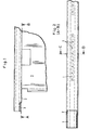
- Figur 1 eine Seitenansicht der Aufhänge-Vorrichtung im Ausschnitt,
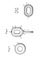
- Figur 2 eine Draufsicht auf die Unterkante der Trageschiene gemäß Schnitt A-B der Figur 1 (in vergrößertem Maßstab),
- Figur 3 einen Querschnitt durch den Rohrverbundkörper vor der Pressung,
- Figur 4 einen Querschnitt durch den verformten und verschweißten Verbundkörper mit Kathodenblech,
- Figur 5 einen Querschnitt des spanlos verformten Verbundkörpers entlang der Linie C-D der Fig. 2 (in vergrößertem Maßstab),
- Figur 6 eine Seitenansicht des Schienenendes der Aufhängevorrichtung mit Kathode, wobei das Ende der Trageschiene auf dem Stromkontakt des Elektrolysebehälters aufliegt,
- Figur 7 eine Seitenansicht entsprechend der Fig. 6 mit einer anderen Ausführungsform der Ausnehmung des unteren Mantelendes.
- In Fig. 1 ist das Kathodenblech 1 mit dem Edelstahlmantel 2, der das Kupferhohlprofil 3 umschließt, verschweißt. Am Ende der Trageschiene liegt das Kupferprofil infolge der Ausnehmung bzw. Ausklinkung im Mantel als Kontaktstelle offen.
- In Fig. 2 ist in der Draufsicht von unten ein Schnitt entlang der Linie A-B der Fig. 1 dargestellt. Im Bereich des Verbundes von Kathodenblech 1 mit dem Mantel 2 ist mit Bezugszeichen 3 eine kontaktverbessernde Körnerreihe angedeutet.
- Fig. 3 zeigt einen Verbundkörper aus einem Kupferrohr 3 mit einer Ummantelung 2 aus einem Edelstahlrohr vor der spanlosen Formgebung.
- In Fig. 4 ist die ovale Trageschiene aus Verbundrohr mit dem Kathodenblech im Schnitt nach der spanlosen Formgebung dargestellt. Das Kathodenblech 1 ist über die Schweißnaht 7 mit der Ummantelung 2 verbunden. Die Schweißstellen 6 dichten den Übergang Kupferprofil/Edelstahlmantel an der Ausnehmung im Mantel diffusionsdicht ab. Bezugszeichen 5 gibt eine Schweißnaht an, die einen Längsschlitz in der oberen Mantellinie des Edelstahlprofils abdichtet und einen Stromübergang vom stromführenden Kernprofil zum Mantelprofil bewirkt.
- Fig. 5 ist ein Schnitt entlang der Linie C-D der Fig. 2. Mit 4 ist eine kräftige Körnung bezeichnet, die auf die Ummantelung 2 und das innere Hohlprofil 3 einwirkt und einen zusätzlichen Kontaktpunkt schafft.
- In Fig. 6 ist in einer Seitenansicht der Endteil der Aufhänge- vorrichtung dargestellt. Der Verbundkörper aus Kupferhohlprofil 3 und Edelstahlmantel 2, durch Schweißungen 6 mit diesem verbunden, liegt mit dem mantelfreien Teil auf der Stromschiene 8 der Wandung 9 des Elektrolysebehälters auf.
- Die Darstellung in Fig. 7 entpricht derjenigen der Fig. 6, jedoch mit der Ausnahme, daß das untere Mantelende eine nach außen und zur Profilachse ansteigende Ausnehmung aufweist.
Claims (6)
Priority Applications (1)
| Application Number | Priority Date | Filing Date | Title |
|---|---|---|---|
| AT85200855T ATE30605T1 (de) | 1984-09-19 | 1985-05-29 | Stromzufuehrende aufhaengevorrichtung fuer kathoden. |
Applications Claiming Priority (2)
| Application Number | Priority Date | Filing Date | Title |
|---|---|---|---|
| DE3434278 | 1984-09-19 | ||
| DE19843434278 DE3434278A1 (de) | 1984-09-19 | 1984-09-19 | Stromzufuehrende aufhaengevorrichtung fuer kathoden |
Publications (2)
| Publication Number | Publication Date |
|---|---|
| EP0175395A1 true EP0175395A1 (de) | 1986-03-26 |
| EP0175395B1 EP0175395B1 (de) | 1987-11-04 |
Family
ID=6245719
Family Applications (1)
| Application Number | Title | Priority Date | Filing Date |
|---|---|---|---|
| EP85200855A Expired EP0175395B1 (de) | 1984-09-19 | 1985-05-29 | Stromzuführende Aufhängevorrichtung für Kathoden |
Country Status (9)
| Country | Link |
|---|---|
| US (1) | US4647358A (de) |
| EP (1) | EP0175395B1 (de) |
| JP (1) | JPS6173895A (de) |
| AT (1) | ATE30605T1 (de) |
| AU (1) | AU569016B2 (de) |
| DE (2) | DE3434278A1 (de) |
| ES (1) | ES295679Y (de) |
| FI (1) | FI78739C (de) |
| PL (1) | PL142261B2 (de) |
Cited By (6)
| Publication number | Priority date | Publication date | Assignee | Title |
|---|---|---|---|---|
| EP0284128A1 (de) * | 1987-03-05 | 1988-09-28 | den Hartog, Gerardus Henrikus Josephus | Aufhängeschiene für Anoden- und/oder Kathodenbleche, anwendbar beim elektrolytischen Raffinieren von Metallen, und Methode zur Herstellung einer solchen Aufhängeschiene |
| GB2250629A (en) * | 1990-11-23 | 1992-06-10 | Chloride Silent Power Ltd | Battery of high temperature cells |
| US6531038B2 (en) | 2000-01-25 | 2003-03-11 | Km Europa Metal Ag | Cathode arrangement |
| EP2201159A1 (de) * | 2007-08-24 | 2010-06-30 | Epcm Services Ltd. | Elektrolytische kathodenanordnung und verfahren zur herstellung und verwendung davon |
| US9388501B2 (en) | 2010-10-18 | 2016-07-12 | Epcm Services Ltd. | Electrolytic cathode assemblies with hollow hanger bar |
| WO2017176118A1 (en) * | 2016-04-06 | 2017-10-12 | Beheermaatschappij Clement Weert B.V. | Cathode carrier for use in a electrolysis device, and such an electrolysis device |
Families Citing this family (16)
| Publication number | Priority date | Publication date | Assignee | Title |
|---|---|---|---|---|
| CA1263627A (en) * | 1986-02-06 | 1989-12-05 | Kidd Creek Mines Ltd. | Cathode hangers |
| JP2615863B2 (ja) * | 1988-06-20 | 1997-06-04 | 三菱マテリアル株式会社 | 電解用陰極板 |
| BE1004728A3 (fr) * | 1991-04-18 | 1993-01-19 | Solvay | Conducteur electrique, procede de fabrication d'un conducteur electrique et electrode pour cellule d'electrolyse. |
| DE4241485C1 (de) * | 1992-12-09 | 1994-03-17 | Siemens Ag | Kathode zum galvanischen Abscheiden von Kupfer und Verfahren zu ihrer Herstellung |
| DE9309768U1 (de) * | 1993-07-01 | 1993-11-04 | Metzka Gmbh | Kontaktiereinrichtung für ein Leiterplattengestell einer Galvanikanlage |
| US5492609A (en) * | 1994-10-21 | 1996-02-20 | T. A. Caid Industries, Inc. | Cathode for electrolytic refining of copper |
| US5584975A (en) * | 1995-06-15 | 1996-12-17 | Eltech Systems Corporation | Tubular electrode with removable conductive core |
| US5976333A (en) * | 1998-01-06 | 1999-11-02 | Pate; Ray H. | Collector bar |
| FI108546B (fi) * | 1998-09-24 | 2002-02-15 | Outokumpu Oy | Menetelmä katodin ripustustangon valmistamiseksi |
| AUPQ584800A0 (en) * | 2000-02-25 | 2000-03-16 | Comalco Aluminium Limited | An electrical reduction cell |
| AU2001235261B2 (en) * | 2000-02-25 | 2005-06-02 | Comalco Aluminium Limited | An electrolytic reduction cell and collector bar |
| FI110519B (fi) * | 2000-11-17 | 2003-02-14 | Outokumpu Oy | Menetelmä vaippaosan ja ydinosan liittämiseksi toisiinsa |
| CL2004000941A1 (es) * | 2004-05-03 | 2005-03-11 | Ind Proveedora De Partes Metal | Zona de union resistente a la corrosion entre cobre y acero inoxidable o titanio, formada por una primera zona de aleacion de cobre-niquel, una zona intermedia con aleacion de niquel o niquel puro y una segunda zona de aleacion de acero inoxidable-ni |
| US7807028B2 (en) | 2005-03-09 | 2010-10-05 | Xstrata Queensland Limited | Stainless steel electrolytic plates |
| US20130119032A1 (en) * | 2011-11-11 | 2013-05-16 | Lincoln Global, Inc. | System and method for welding materials of different conductivity |
| PL2900848T3 (pl) | 2012-09-26 | 2021-06-14 | Steelmore Holdings Pty Ltd | Katoda i sposób wytwarzania |
Citations (4)
| Publication number | Priority date | Publication date | Assignee | Title |
|---|---|---|---|---|
| DE2550178A1 (de) * | 1974-11-08 | 1976-05-26 | Imp Metal Ind Kynoch Ltd | Zusammenstellung aus kathode und haengeschiene |
| DE2704686A1 (de) * | 1976-02-06 | 1977-08-11 | Imp Metal Ind Kynoch Ltd | Zusammenstellung aus kathode und haengeschiene |
| FR2388062A1 (fr) * | 1977-04-21 | 1978-11-17 | Ugine Aciers | Bordures isolantes de cathodes pour depots metalliques par electrolyse |
| GB2041002A (en) * | 1979-01-23 | 1980-09-03 | Imi Kynoch Ltd | Electrode suspension bars |
Family Cites Families (10)
| Publication number | Priority date | Publication date | Assignee | Title |
|---|---|---|---|---|
| US2434731A (en) * | 1943-11-16 | 1948-01-20 | Baker & Co Inc | Platinum sheet electrode |
| GB1087529A (en) * | 1965-11-04 | 1967-10-18 | Murgatroyds Salt & Chem | Improvements in or relating to electrolytic diaphragm cells |
| DE2434214B2 (de) * | 1974-07-16 | 1978-06-15 | Imperial Metal Industries Kynoch Ltd., Witton, Birmingham (Grossbritannien) | Aufhängevorrichtung für Kathoden in Elektrogewinnungs- oder Elektroraffinationszellen |
| US4033849A (en) * | 1975-05-09 | 1977-07-05 | Diamond Shamrock Corporation | Electrode and apparatus for forming the same |
| DE2751047C2 (de) * | 1977-11-15 | 1980-07-03 | H. Maihak Ag, 2000 Hamburg | Nichtdispersives Infrarot-Gasanalysengerät |
| US4121994A (en) * | 1977-11-17 | 1978-10-24 | Hooker Chemicals & Plastics Corp. | Anode support means for an electrolytic cell |
| IE49702B1 (en) * | 1979-04-28 | 1985-11-27 | Imi Kynoch Ltd | Electrode |
| ZA817441B (en) * | 1980-11-21 | 1982-10-27 | Imi Kynoch Ltd | Anode |
| US4373654A (en) * | 1980-11-28 | 1983-02-15 | Rsr Corporation | Method of manufacturing electrowinning anode |
| US4391695A (en) * | 1981-02-03 | 1983-07-05 | Conradty Gmbh Metallelektroden Kg | Coated metal anode or the electrolytic recovery of metals |
-
1984
- 1984-09-19 DE DE19843434278 patent/DE3434278A1/de not_active Withdrawn
-
1985
- 1985-05-23 ES ES1985295679U patent/ES295679Y/es not_active Expired
- 1985-05-23 FI FI852068A patent/FI78739C/fi not_active IP Right Cessation
- 1985-05-29 AT AT85200855T patent/ATE30605T1/de not_active IP Right Cessation
- 1985-05-29 DE DE8585200855T patent/DE3560912D1/de not_active Expired
- 1985-05-29 EP EP85200855A patent/EP0175395B1/de not_active Expired
- 1985-06-07 JP JP60124050A patent/JPS6173895A/ja active Pending
- 1985-08-05 US US06/762,603 patent/US4647358A/en not_active Expired - Fee Related
- 1985-09-17 PL PL1985255397A patent/PL142261B2/xx unknown
- 1985-09-18 AU AU47589/85A patent/AU569016B2/en not_active Ceased
Patent Citations (4)
| Publication number | Priority date | Publication date | Assignee | Title |
|---|---|---|---|---|
| DE2550178A1 (de) * | 1974-11-08 | 1976-05-26 | Imp Metal Ind Kynoch Ltd | Zusammenstellung aus kathode und haengeschiene |
| DE2704686A1 (de) * | 1976-02-06 | 1977-08-11 | Imp Metal Ind Kynoch Ltd | Zusammenstellung aus kathode und haengeschiene |
| FR2388062A1 (fr) * | 1977-04-21 | 1978-11-17 | Ugine Aciers | Bordures isolantes de cathodes pour depots metalliques par electrolyse |
| GB2041002A (en) * | 1979-01-23 | 1980-09-03 | Imi Kynoch Ltd | Electrode suspension bars |
Cited By (9)
| Publication number | Priority date | Publication date | Assignee | Title |
|---|---|---|---|---|
| EP0284128A1 (de) * | 1987-03-05 | 1988-09-28 | den Hartog, Gerardus Henrikus Josephus | Aufhängeschiene für Anoden- und/oder Kathodenbleche, anwendbar beim elektrolytischen Raffinieren von Metallen, und Methode zur Herstellung einer solchen Aufhängeschiene |
| US4871436A (en) * | 1987-03-05 | 1989-10-03 | Den Hartog Gerardus H J | Suspension bar for anode and/or cathode sheets in the electrolytic refining of metals and a method for the manufacture of such a suspension bar |
| GB2250629A (en) * | 1990-11-23 | 1992-06-10 | Chloride Silent Power Ltd | Battery of high temperature cells |
| US6531038B2 (en) | 2000-01-25 | 2003-03-11 | Km Europa Metal Ag | Cathode arrangement |
| EP2201159A1 (de) * | 2007-08-24 | 2010-06-30 | Epcm Services Ltd. | Elektrolytische kathodenanordnung und verfahren zur herstellung und verwendung davon |
| EP2201159A4 (de) * | 2007-08-24 | 2010-09-29 | Epcm Services Ltd | Elektrolytische kathodenanordnung und verfahren zur herstellung und verwendung davon |
| US8337679B2 (en) | 2007-08-24 | 2012-12-25 | Epcm Services Ltd. | Electrolytic cathode assemblies and methods of manufacturing and using same |
| US9388501B2 (en) | 2010-10-18 | 2016-07-12 | Epcm Services Ltd. | Electrolytic cathode assemblies with hollow hanger bar |
| WO2017176118A1 (en) * | 2016-04-06 | 2017-10-12 | Beheermaatschappij Clement Weert B.V. | Cathode carrier for use in a electrolysis device, and such an electrolysis device |
Also Published As
| Publication number | Publication date |
|---|---|
| FI78739B (fi) | 1989-05-31 |
| AU569016B2 (en) | 1988-01-14 |
| ES295679U (es) | 1987-03-16 |
| US4647358A (en) | 1987-03-03 |
| DE3434278A1 (de) | 1986-04-17 |
| PL142261B2 (en) | 1987-10-31 |
| FI78739C (fi) | 1989-09-11 |
| DE3560912D1 (en) | 1987-12-10 |
| AU4758985A (en) | 1986-03-27 |
| ATE30605T1 (de) | 1987-11-15 |
| JPS6173895A (ja) | 1986-04-16 |
| PL255397A2 (en) | 1986-07-15 |
| FI852068L (fi) | 1986-03-20 |
| EP0175395B1 (de) | 1987-11-04 |
| ES295679Y (es) | 1987-11-01 |
| FI852068A0 (fi) | 1985-05-23 |
Similar Documents
| Publication | Publication Date | Title |
|---|---|---|
| EP0175395B1 (de) | Stromzuführende Aufhängevorrichtung für Kathoden | |
| DE2043560A1 (de) | Anodenzusammenstellung | |
| DE2812055C2 (de) | Bipolare Elektrode | |
| EP0089475B1 (de) | Beschichtete Ventilmetallanode zur elektrolytischen Gewinnung von Metallen oder Metalloxiden | |
| DE2711610C2 (de) | Wiederbenutzbare Kathodeneinheit mit einer Arbeitsfläche zur chargenweisen galvanischen Beschichtung mit mehreren getrennten Metallablagerungen | |
| EP0167790A2 (de) | Beschichtete Ventilmetall-Elektrode zur elektrolytischen Galvanisierung | |
| DE3003927C2 (de) | Kathode für die elektrolytische Raffination von Kupfer | |
| DE1467075B2 (de) | Anode zur elektrolytischen Herstellung von Chlor | |
| DE3406797C2 (de) | Beschichtete Ventilmetallanode zur elektrolytischen Gewinnung von Metallen oder Metalloxiden | |
| DE19927379A1 (de) | Kathoden-Formstück zur Kupferbeschichtung | |
| DE2830288C2 (de) | ||
| DE4241433A1 (de) | Dauerelektrodenvorrichtung für die Kupferraffination sowie Verfahren zu deren Herstellung | |
| DE4241485C1 (de) | Kathode zum galvanischen Abscheiden von Kupfer und Verfahren zu ihrer Herstellung | |
| DE2427891B2 (de) | Anode für elektrolytische Zellen | |
| DE2833499A1 (de) | Anode fuer elektrolytische zellen | |
| DE10029837B4 (de) | Verfahren zur Herstellung von einseitig platinierten Platten und Streckmetallgittern aus Refraktärmetallen | |
| DE3406777C2 (de) | Beschichtete Ventilmetallanode zur elektrolytischen Gewinnung von Metallen oder Metalloxiden | |
| EP0107135A1 (de) | Bipolare Elektrode | |
| DE60200887T2 (de) | Kathode für die elektroraffinierung oder elektrogewinnung von kupfer | |
| DE2550178C3 (de) | Elektrodenhalterung | |
| DE10003012A1 (de) | Kathodenanordnung | |
| EP1207218A1 (de) | Kathodenblech | |
| DE1467075C (de) | Anode zur elektrolytischen Herstellung von Chlor | |
| DE3406823C2 (de) | Beschichtete Ventilmetallanode zur elektrolytischen Gewinnung von Metallen oder Metalloxiden | |
| DE4238739C2 (de) | Kathode für die elektrolytische Raffination von Nichteisenmetallen, insbesondere Kupfer |
Legal Events
| Date | Code | Title | Description |
|---|---|---|---|
| PUAI | Public reference made under article 153(3) epc to a published international application that has entered the european phase |
Free format text: ORIGINAL CODE: 0009012 |
|
| AK | Designated contracting states |
Kind code of ref document: A1 Designated state(s): AT BE CH DE FR GB IT LI SE |
|
| 17P | Request for examination filed |
Effective date: 19860516 |
|
| 17Q | First examination report despatched |
Effective date: 19870127 |
|
| GRAA | (expected) grant |
Free format text: ORIGINAL CODE: 0009210 |
|
| AK | Designated contracting states |
Kind code of ref document: B1 Designated state(s): AT BE DE FR GB IT SE |
|
| REF | Corresponds to: |
Ref document number: 30605 Country of ref document: AT Date of ref document: 19871115 Kind code of ref document: T |
|
| REF | Corresponds to: |
Ref document number: 3560912 Country of ref document: DE Date of ref document: 19871210 |
|
| ET | Fr: translation filed | ||
| ITF | It: translation for a ep patent filed |
Owner name: STUDIO JAUMANN |
|
| GBT | Gb: translation of ep patent filed (gb section 77(6)(a)/1977) | ||
| PLBE | No opposition filed within time limit |
Free format text: ORIGINAL CODE: 0009261 |
|
| STAA | Information on the status of an ep patent application or granted ep patent |
Free format text: STATUS: NO OPPOSITION FILED WITHIN TIME LIMIT |
|
| 26N | No opposition filed | ||
| ITTA | It: last paid annual fee | ||
| PGFP | Annual fee paid to national office [announced via postgrant information from national office to epo] |
Ref country code: FR Payment date: 19900612 Year of fee payment: 6 |
|
| PGFP | Annual fee paid to national office [announced via postgrant information from national office to epo] |
Ref country code: GB Payment date: 19900711 Year of fee payment: 6 |
|
| PGFP | Annual fee paid to national office [announced via postgrant information from national office to epo] |
Ref country code: SE Payment date: 19900716 Year of fee payment: 6 |
|
| PGFP | Annual fee paid to national office [announced via postgrant information from national office to epo] |
Ref country code: AT Payment date: 19900731 Year of fee payment: 6 |
|
| PGFP | Annual fee paid to national office [announced via postgrant information from national office to epo] |
Ref country code: BE Payment date: 19900806 Year of fee payment: 6 |
|
| PGFP | Annual fee paid to national office [announced via postgrant information from national office to epo] |
Ref country code: DE Payment date: 19900813 Year of fee payment: 6 |
|
| PG25 | Lapsed in a contracting state [announced via postgrant information from national office to epo] |
Ref country code: GB Effective date: 19910529 Ref country code: AT Effective date: 19910529 |
|
| PG25 | Lapsed in a contracting state [announced via postgrant information from national office to epo] |
Ref country code: SE Effective date: 19910530 |
|
| PG25 | Lapsed in a contracting state [announced via postgrant information from national office to epo] |
Ref country code: BE Effective date: 19910531 |
|
| BERE | Be: lapsed |
Owner name: NORDDEUTSCHE AFFINERIE A.G. Effective date: 19910531 |
|
| GBPC | Gb: european patent ceased through non-payment of renewal fee | ||
| PG25 | Lapsed in a contracting state [announced via postgrant information from national office to epo] |
Ref country code: FR Effective date: 19920131 |
|
| PG25 | Lapsed in a contracting state [announced via postgrant information from national office to epo] |
Ref country code: DE Effective date: 19920303 |
|
| REG | Reference to a national code |
Ref country code: FR Ref legal event code: ST |
|
| EUG | Se: european patent has lapsed |
Ref document number: 85200855.6 Effective date: 19911209 |