EP0168331A2 - Maschine zum Biegen von Rohren, Stangen oder Profilen - Google Patents
Maschine zum Biegen von Rohren, Stangen oder Profilen Download PDFInfo
- Publication number
- EP0168331A2 EP0168331A2 EP85420086A EP85420086A EP0168331A2 EP 0168331 A2 EP0168331 A2 EP 0168331A2 EP 85420086 A EP85420086 A EP 85420086A EP 85420086 A EP85420086 A EP 85420086A EP 0168331 A2 EP0168331 A2 EP 0168331A2
- Authority
- EP
- European Patent Office
- Prior art keywords
- bending
- machine
- tube
- jaw
- bending head
- Prior art date
- Legal status (The legal status is an assumption and is not a legal conclusion. Google has not performed a legal analysis and makes no representation as to the accuracy of the status listed.)
- Granted
Links
- 238000005452 bending Methods 0.000 title claims abstract description 94
- 238000006073 displacement reaction Methods 0.000 claims description 4
- 230000007246 mechanism Effects 0.000 claims description 3
- 230000009471 action Effects 0.000 claims description 2
- 230000007480 spreading Effects 0.000 claims description 2
- 230000008859 change Effects 0.000 description 4
- 238000010276 construction Methods 0.000 description 2
- 238000010586 diagram Methods 0.000 description 2
- 230000009467 reduction Effects 0.000 description 2
- 240000007817 Olea europaea Species 0.000 description 1
- 239000003638 chemical reducing agent Substances 0.000 description 1
- 239000012530 fluid Substances 0.000 description 1
- 238000009434 installation Methods 0.000 description 1
- 238000004519 manufacturing process Methods 0.000 description 1
- 238000011084 recovery Methods 0.000 description 1
Images
Classifications
-
- B—PERFORMING OPERATIONS; TRANSPORTING
- B21—MECHANICAL METAL-WORKING WITHOUT ESSENTIALLY REMOVING MATERIAL; PUNCHING METAL
- B21D—WORKING OR PROCESSING OF SHEET METAL OR METAL TUBES, RODS OR PROFILES WITHOUT ESSENTIALLY REMOVING MATERIAL; PUNCHING METAL
- B21D7/00—Bending rods, profiles, or tubes
- B21D7/02—Bending rods, profiles, or tubes over a stationary forming member; by use of a swinging forming member or abutment
- B21D7/024—Bending rods, profiles, or tubes over a stationary forming member; by use of a swinging forming member or abutment by a swinging forming member
Definitions
- the present invention relates to a machine intended for bending tubes, bars or profiles. More particularly, this invention relates to a machine in which the bending tool mainly comprises a rotary forming roller of vertical axis, having an annular groove and supporting a first jaw - a second jaw carried by a bending arm mounted pivoting around the vertical axis mentioned above, the second jaw being able to be brought opposite the first jaw so as to grip the tube or the like to bend - a horizontal strip able to be applied against the tube or the like to bend, behind the jaws, this strip being movable, remaining parallel to itself, in the direction of its approach or its distance from the horizontal axis along which is positioned the tube or the like to bend.
- the part of the tube to be bent is clamped between the two jaws and driven forward by the rotation of the bending arm, so as to wind in the groove of the forming roller.
- the angle of rotation of the arm determines the angle of bending
- the radius of the forming roller determines the radius of the elbow that the tube will ultimately have.
- the movable strip applied against the tube behind the part to be bent, avoids any unwanted deformation of the tube outside the part to be bent.
- a bending head movable in the transverse direction of the frame of the machine, supports all the bending tools, that is to say the forming roller with the first jaw, the arm of bending carrying the second jaw, and the strip.
- the tube to be bent is pinched, in its part remaining rectilinear, by a clamping mandrel carried by a carriage movable in longitudinal direction, which keeps this part of the tube positioned along a determined horizontal axis, parallel to the longitudinal direction of the frame of the machine. .
- the present invention avoids these drawbacks.
- the assembly comprising the forming roller and the first associated jaw, as well as the bending arm pivoting with the second jaw, is carried by a movable bending head, under the action of control means, in a horizontal direction transversely to the frame of the machine and to the axis along which the tube or the like to be bent is positioned, while the movable strip, with its means of movement control, is mounted directly on the machine frame, without connection to the bending head.
- the strip is thus completely dissociated from the bending head which supports the forming roller, the bending arm and the two jaws.
- the means for controlling the transverse displacement of the bending head, carrying the forming roller, the bending arm and the two jaws comprise on the one hand a control means for the initial positioning of the bending head , placing the vertical axis of the forming roller in the appropriate position as a function of the radius of this roller, and on the other hand a control means for the offset of said bending head, capable of spreading the axis of the forming roller from the 'axis along which is positioned the tube or the like to bend.
- the initial position adjustment of the vertical axis of the forming roller, as a function of the diameter of this roller, can be carried out without influencing the position of the strip which is mounted on a support independent of the bending head.
- the shifting control of the bending head makes it possible to release the forming roller and the first jaw from the tube, which makes it possible to easily modify the orientation of the tube. between two successive bending operations, even if it is a section tube for example square.
- the offset of the bending head also facilitates a possible change of jaw between two successive bending operations.
- the means for controlling the transverse displacement of the bending head comprise, on the one hand, a mechanism with threaded rod and nut, with rotary drive of one of these elements, for the initial positioning of the bending head, and on the other hand a double-acting cylinder, for the offset of said bending head.
- the threaded rod is rotatably mounted and is engaged with a nut secured to the bending head, this threaded rod being linked in rotation with a primary drive shaft relative to which it is axially displaceable, while that the double-acting cylinder, arranged coaxially with the threaded rod, comprises an annular piston axially linked to the threaded rod.
- the annular piston is advantageously secured to a sleeve which slides in the two flanges of the jack and which is connected in translation with the rotary threaded rod by means of at least one bearing.
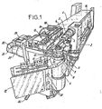
- the machine for bending tubes shown in the drawing, comprises an elongated frame (1) which supports longitudinal guides along which a carriage (2) can be moved in the horizontal direction. At the upper part of the carriage (2) is provided a clamping mandrel (3), able to pinch the bending tube (4) while maintaining it along a determined horizontal axis (5), while allowing the advancement of this tube (4) along the axis (5) and its rotation around said axis (5).
- a bending head (6) mounted horizontally movable, in a direction transverse to the frame (1).
- the tool which allows the bending to be carried out mainly comprises: a forming roller (7) with a vertical axis (8), having an annular groove (9) and supporting a first jaw (10) - a second jaw (11), carried by a bending arm (12) pivotally mounted about the vertical axis (8) - a strip (13) extending parallel to the horizontal axis (5) and having a longitudinal groove (14).
- This tool is completed by an olive (15) placed at the end of a horizontal rod (16) which passes through the clamping mandrel (3) and is introduced into the tube to be bent (4).
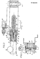
- the bending head (6) to which the vertical axis (8) is linked, is slidably mounted, by a dovetail part (17), along two sliders with inclined faces (18,19) fixed at the front of the frame (1) - see in particular figure 3.
- an electric motor (20) is provided which, by means of a reduction gear speed (21), rotates a primary shaft (22) hollow over a part of its length where it has internal longitudinal grooves. The latter are engaged with a grooved part (23) of a rotary threaded rod (24), coaxial with the shaft (22) and itself engaged with a nut (25) immobilized in rotation in the bending head.
- (6) - see figures 2 and 3.
- the speed reducer housing (21) is integral with the rear flange (26) of a double-acting cylinder (27) whose body (28), coaxial with the shaft (22) , is closed at the front by another flange (29).
- an annular piston (30) integral with a sleeve (31) which slides in the two flanges (26,29).
- the sleeve (31) is closed by a cover (32) which is crossed by the primary shaft (22).
- the front end of the sleeve (31) is linked in translation with the threaded rod (24), by means of bearings (33) and suitable stops.
- Channels (34, 35) are drilled in the two flanges (26, 29), to supply fluid to the two chambers of the jack (27) located on either side of the annular piston (30) - see figure 2.
- the strip (13) is movable relative to the frame (1) in a longitudinal direction, under the control of a feed cylinder (38), and also in a transverse direction, under the control of a cylinder approach (39).
- the bending head (6) with the forming roller (7) and the bending arm (12), is adjustable in transverse position by means of the motor (20), via the reduction gear (21), the primary shaft (22), threaded rod (24) and nut (25).
- the transverse movement of the bending head (6) thus controlled, makes it possible to position the vertical axis (8) adequately as a function of the diameter of the forming roller (7), itself chosen according to the characteristics desired for the elbow to train.
- the jack (27) makes it possible to move the bending head (6), still in transverse direction, over a stroke (C) determined so as to obtain an offset of this head (6), allowing free rotation of the tube to bend (4), in particular in the case of a tube of non-circular section, for example a tube (4) of square section.
- the displacement of the strip (13) is controlled independently of that of the bending head (6), by means of the two jacks (38, 39).
- the jack (36) makes it possible to raise the second jaw (11), to place it opposite the first jaw (10), or to lower it by moving it away from the first jaw (10), in order to allow the introduction of the bending tube. (4).
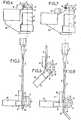
- FIGS. 4 to 12 show the successive stages of the double bending of a tube (4) of square section, on the bending machine object of the invention.
- the initially straight tube (4) is assumed, at the start, to be positioned in an angular position defined along the horizontal axis (5), and clamped by the mandrel (3) as well as, in its part to be bent first, by the two jaws (10.11).
- the bending arm (12) is initially oriented perpendicular to the axis (5), and the strip (13) is applied against the tube (4), behind the second jaw (11) - see Figures 4 and 5.
- the first bending of the tube (4) is then carried out, by controlling the rotation of the bending arm (12) around the vertical axis (8) according to the desired angle, the tube (4) then bending while being guided in the groove (9) of the forming roller (7) - see Figure 6. Then the second jaw (11) is retracted, and the bending arm (12) is returned to its initial angular position - see Figure 7. The strip (13) is moved away from the tube (4) which then has a first bend (40). The carriage with the mandrel (3) is advanced, so as to push the tube (4) forward, releasing the elbow (40) from the roller (7) - see Figure 8.
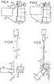
- the next phase consists in actuating the jack (27) in a given direction, which shifts the entire bending head (6) by the distance (C) relative to the horizontal axis (5) - see Figure 9.
- the tube (4) thus freed, is turned using the clamping mandrel (3) around the axis (5) according to the arrow (41 ), for example at an angle of rotation of 180 ° so that its end previously bent to the right is turned to the left - see Figures 9 and 10.
- the bending head (6) is reset to its initial position by actuating the jack (27) in the opposite direction; the second jaw (11) is again clamped against the tube (4) - see figure 11.
- the strip (13) is also applied again against the tube (4), and the bending arm (12) is actuated as previously.
- a second bend (42) is thus produced, in a direction opposite to the first and, in the case taken here for example, situated in the same plane as the first 'bend (40) - see FIG. 12.
- the offset of the bending head (6), controlled by the jack (27), can also be used to facilitate a change of jaws (10), for example during the production of close bends requiring the installation of recovery jaw on the forming roller (7).
- the machine according to the invention applies not only to the bending of tubes (4) of all sections, but also to the bending of bars, profiles and other similar objects.
- the invention is not limited to the sole embodiment of this machine for bending tubes, bars or profiles which has been described above, by way of example; on the contrary, it embraces all of the variant embodiments and applications respecting the same principle.
- the jack (27) can be replaced by any equivalent means, making it possible to control an offset of the bending head (6).
Landscapes
- Engineering & Computer Science (AREA)
- Mechanical Engineering (AREA)
- Bending Of Plates, Rods, And Pipes (AREA)
Priority Applications (1)
| Application Number | Priority Date | Filing Date | Title |
|---|---|---|---|
| AT85420086T ATE53950T1 (de) | 1984-07-10 | 1985-05-09 | Maschine zum biegen von rohren, stangen oder profilen. |
Applications Claiming Priority (2)
| Application Number | Priority Date | Filing Date | Title |
|---|---|---|---|
| FR8411321A FR2567429B1 (fr) | 1984-07-10 | 1984-07-10 | Machine pour le cintrage de tubes, barres ou profiles |
| FR8411321 | 1984-07-10 |
Publications (3)
| Publication Number | Publication Date |
|---|---|
| EP0168331A2 true EP0168331A2 (de) | 1986-01-15 |
| EP0168331A3 EP0168331A3 (en) | 1986-10-08 |
| EP0168331B1 EP0168331B1 (de) | 1990-06-20 |
Family
ID=9306204
Family Applications (1)
| Application Number | Title | Priority Date | Filing Date |
|---|---|---|---|
| EP85420086A Expired - Lifetime EP0168331B1 (de) | 1984-07-10 | 1985-05-09 | Maschine zum Biegen von Rohren, Stangen oder Profilen |
Country Status (8)
| Country | Link |
|---|---|
| US (1) | US4625531A (de) |
| EP (1) | EP0168331B1 (de) |
| JP (1) | JPS6138720A (de) |
| AT (1) | ATE53950T1 (de) |
| CA (1) | CA1291697C (de) |
| DE (1) | DE3578316D1 (de) |
| ES (1) | ES8607768A1 (de) |
| FR (1) | FR2567429B1 (de) |
Cited By (2)
| Publication number | Priority date | Publication date | Assignee | Title |
|---|---|---|---|---|
| EP0319400A1 (de) * | 1987-12-02 | 1989-06-07 | Societe Nationale D'etude Et De Construction De Moteurs D'aviation, "S.N.E.C.M.A." | Rohrleitungsbiegegerät und Verfahren zum Herstellen einer Rohrleitung mit geschweisstem Ansatzstück |
| ITRM20130259A1 (it) * | 2013-05-02 | 2014-11-03 | Cml Int Spa | Macchina curvatrice del tipo a matrice e contromatrice per curvare a destra e a sinistra un pezzo allungato |
Families Citing this family (14)
| Publication number | Priority date | Publication date | Assignee | Title |
|---|---|---|---|---|
| US4959984A (en) * | 1989-08-17 | 1990-10-02 | Ap Parts Manufacturing Company | Precision bending apparatus |
| JP2947362B2 (ja) * | 1989-09-07 | 1999-09-13 | 臼井国際産業株式会社 | チューブの曲げ装置 |
| DE4124715C2 (de) * | 1990-07-26 | 1994-11-24 | Usui Kokusai Sangyo Kk | Vorrichtung zum mehrfachen Abbiegen eines Metallrohrs |
| US5570508A (en) * | 1993-12-03 | 1996-11-05 | Itt Industries, Inc. | Method of making a high strength automotive seat frame |
| US6009737A (en) * | 1997-07-17 | 2000-01-04 | Arvin Industries, Inc. | Tube bender |
| US6155091A (en) * | 1999-02-26 | 2000-12-05 | Arvin Industries, Inc. | Mandrel assembly for tube-bending apparatus |
| NO311638B1 (no) | 1999-05-21 | 2001-12-27 | Skipskonsult As | Fremgangsmåter for fremstilling av sammenhengende strekk av sirkul¶rsylindriske legemer, anvendelse av et verktöy, og enrörlengde og rördeler |
| US6434995B1 (en) | 1999-10-15 | 2002-08-20 | Usui Kokusai Sangyo Kaisha Limited | Method of bending small diameter metal pipe and its apparatus |
| ES2303540T3 (es) * | 2002-07-13 | 2008-08-16 | Trumpf Werkzeugmaschinen Gmbh + Co. Kg | Maquina de doblar tubos con herramienta de doblar y dispositivo de retroceso de mandril. |
| JP4515056B2 (ja) * | 2003-08-01 | 2010-07-28 | 三桜工業株式会社 | 管の曲げ加工装置 |
| IT1396456B1 (it) * | 2009-11-24 | 2012-11-23 | Piegatrici Macch Elettr | Attrezzatura per la piegatura di prodotti metallici oblunghi, quali barre, tondini, o fili metallici, e relativo procedimento di piegatura |
| ITRM20120619A1 (it) * | 2012-12-06 | 2014-06-07 | Libero Angelo Massaro | Macchina perfezionata per curvare tubi metallici, sia a destra che a sinistra rispetto alla direzione di introduzione del tubo. |
| US9908169B2 (en) * | 2013-09-06 | 2018-03-06 | Winton Machine Company | Process to cut coax cable |
| CN110202029B (zh) * | 2019-06-18 | 2020-09-01 | 深圳市朗奥洁净科技股份有限公司 | 一种管材自动化数控多段折弯装置 |
Family Cites Families (10)
| Publication number | Priority date | Publication date | Assignee | Title |
|---|---|---|---|---|
| US2740454A (en) * | 1952-10-02 | 1956-04-03 | Western Electric Co | Apparatus for making diagonal twisted or skew bends in wave guide tubing |
| DE1962590A1 (de) * | 1969-12-13 | 1971-06-24 | Hilgers Maschinen U App Bauans | Rohrbiegemaschine |
| DE2101162A1 (de) * | 1971-01-12 | 1972-07-20 | J. Banning Ag, 4700 Hamm | Rohrbiegemaschine |
| DE2537382A1 (de) * | 1975-08-22 | 1977-03-03 | Babcock Ag | Vorrichtung zum biegen von rohren |
| US4063441A (en) * | 1975-09-19 | 1977-12-20 | Eaton-Leonard Corporation | Apparatus for bending tubes |
| US4126030A (en) * | 1977-10-03 | 1978-11-21 | Eaton-Leonard Corporation | Retractable pressure die |
| JPS5930325B2 (ja) * | 1977-12-28 | 1984-07-26 | 日本電気株式会社 | アイソレ−タ |
| US4178788A (en) * | 1978-03-24 | 1979-12-18 | Eaton-Leonard Corporation | Adjustable clamp die |
| DE2910174A1 (de) * | 1979-03-15 | 1980-09-25 | Benteler Werke Ag | Rohrbiegemaschine mit einem mit mehreren biegewerkzeugen versehenen biegekopf |
| JPS5858170B2 (ja) * | 1979-06-20 | 1983-12-23 | 株式会社神戸製鋼所 | シヤ−プレスの刃物交換装置 |
-
1984
- 1984-07-10 FR FR8411321A patent/FR2567429B1/fr not_active Expired - Lifetime
-
1985
- 1985-05-09 DE DE8585420086T patent/DE3578316D1/de not_active Expired - Fee Related
- 1985-05-09 EP EP85420086A patent/EP0168331B1/de not_active Expired - Lifetime
- 1985-05-09 AT AT85420086T patent/ATE53950T1/de not_active IP Right Cessation
- 1985-06-04 CA CA000483145A patent/CA1291697C/fr not_active Expired - Fee Related
- 1985-06-12 ES ES85544059A patent/ES8607768A1/es not_active Expired
- 1985-07-09 JP JP14940085A patent/JPS6138720A/ja active Pending
- 1985-07-09 US US06/753,314 patent/US4625531A/en not_active Expired - Fee Related
Cited By (5)
| Publication number | Priority date | Publication date | Assignee | Title |
|---|---|---|---|---|
| EP0319400A1 (de) * | 1987-12-02 | 1989-06-07 | Societe Nationale D'etude Et De Construction De Moteurs D'aviation, "S.N.E.C.M.A." | Rohrleitungsbiegegerät und Verfahren zum Herstellen einer Rohrleitung mit geschweisstem Ansatzstück |
| FR2624038A1 (fr) * | 1987-12-02 | 1989-06-09 | Snecma | Outillage de cintrage de canalisations et procede de fabrication d'une canalisation a embout soude |
| ITRM20130259A1 (it) * | 2013-05-02 | 2014-11-03 | Cml Int Spa | Macchina curvatrice del tipo a matrice e contromatrice per curvare a destra e a sinistra un pezzo allungato |
| EP2799158A1 (de) | 2013-05-02 | 2014-11-05 | CML International S.p.A. | Biegemaschine mit Stempel und Gegenhalterstempel zum rechts und links Biegen eines länglichen Körpers |
| US9878361B2 (en) | 2013-05-02 | 2018-01-30 | Cml International S.P.A. | Die and counter-die type bending machine for right-hand and left-hand bending an elongated piece |
Also Published As
| Publication number | Publication date |
|---|---|
| DE3578316D1 (de) | 1990-07-26 |
| FR2567429A1 (fr) | 1986-01-17 |
| FR2567429B1 (fr) | 1992-03-27 |
| US4625531A (en) | 1986-12-02 |
| EP0168331A3 (en) | 1986-10-08 |
| JPS6138720A (ja) | 1986-02-24 |
| CA1291697C (fr) | 1991-11-05 |
| ATE53950T1 (de) | 1990-07-15 |
| EP0168331B1 (de) | 1990-06-20 |
| ES544059A0 (es) | 1986-06-16 |
| ES8607768A1 (es) | 1986-06-16 |
Similar Documents
| Publication | Publication Date | Title |
|---|---|---|
| CA1291697C (fr) | Machine pour le cintrage de tubes, barres ou profiles | |
| FR2530980A1 (fr) | Cintreuse a courbures multiples | |
| EP0445044B1 (de) | Rohrbiegevorrichtung mit zwei Biegeköpfen | |
| EP0892686A1 (de) | Maschine zum biegen oder wölben von profilen und biegekopf für solche maschine | |
| FR2630358A1 (fr) | Procede et dispositif pour le controle du retour elastique, lors du cintrage d'un element allonge tel que tube | |
| WO2010116052A1 (fr) | Machine à cintrer pour la réalisation de profilés coudés, notamment de tubes d'échangeurs | |
| FR2554021A1 (fr) | Machine automatique perfectionnee pour cambrer selon une configuration speciale des elements minces et rectilignes, et notamment des fils metalliques | |
| EP3842163A1 (de) | Vorrichtung und verfahren zum biegen | |
| WO2008142252A2 (fr) | Unite de cintrage d'un tub | |
| EP1051268B1 (de) | Rohrbiegevorrichtung und ihre trommeleinrichtung | |
| EP0281488B1 (de) | Drehender Biegekopf für Rohrbiegemaschine | |
| FR2477439A1 (fr) | Cage refouleuse a cylindres reglables en charge | |
| FR2685239A1 (fr) | Machine pour l'usinage de pieces a partir de profiles de grande longueur. | |
| CA1110430A (fr) | Procede d'elimination des contraintes residuelles produites dans un tube par une operation de sertissage et outillage pour la mise en oeuvre de ce procede | |
| FR2464773A1 (fr) | Dispositif pour le tournage de pieces flexibles | |
| FR2859653A1 (fr) | Machine orbitale pour le cintrage des tubes | |
| FR2737674A1 (fr) | Machine a cintrer les tubes avec dispositif de poussee | |
| EP0043750A1 (de) | Vorrichtung zum Formen von Rohren mit kleinem Durchmesser | |
| EP0320408B1 (de) | Steuerungsvorrichtung für die Reglette einer Rohrbiegemaschine | |
| FR2483269A1 (fr) | Ouvreur de bobine | |
| EP0114774B1 (de) | Be- und Entladevorrichtung für Werkstücke mit einem einzelnen Antriebsmotor | |
| EP0517637A1 (de) | Biegekopf mit Mehrfachwerkzeugen für eine Drahtbiegemaschine | |
| FR2823029A1 (fr) | Pince motorisee pour le bridage d'elements allonges | |
| CA2275946A1 (fr) | Machine a cintrer des tubes de faible diametre | |
| FR2826889A1 (fr) | Chariot pour machine a cintrer les tubes |
Legal Events
| Date | Code | Title | Description |
|---|---|---|---|
| PUAI | Public reference made under article 153(3) epc to a published international application that has entered the european phase |
Free format text: ORIGINAL CODE: 0009012 |
|
| AK | Designated contracting states |
Designated state(s): AT BE CH DE GB IT LI LU NL SE |
|
| PUAL | Search report despatched |
Free format text: ORIGINAL CODE: 0009013 |
|
| AK | Designated contracting states |
Kind code of ref document: A3 Designated state(s): AT BE CH DE GB IT LI LU NL SE |
|
| 17P | Request for examination filed |
Effective date: 19870122 |
|
| 17Q | First examination report despatched |
Effective date: 19880121 |
|
| RAP1 | Party data changed (applicant data changed or rights of an application transferred) |
Owner name: EATON LEONARD PICOT S.A. |
|
| GRAA | (expected) grant |
Free format text: ORIGINAL CODE: 0009210 |
|
| AK | Designated contracting states |
Kind code of ref document: B1 Designated state(s): AT BE CH DE GB IT LI LU NL SE |
|
| REF | Corresponds to: |
Ref document number: 53950 Country of ref document: AT Date of ref document: 19900715 Kind code of ref document: T |
|
| ITF | It: translation for a ep patent filed | ||
| REF | Corresponds to: |
Ref document number: 3578316 Country of ref document: DE Date of ref document: 19900726 |
|
| GBT | Gb: translation of ep patent filed (gb section 77(6)(a)/1977) | ||
| PLBE | No opposition filed within time limit |
Free format text: ORIGINAL CODE: 0009261 |
|
| STAA | Information on the status of an ep patent application or granted ep patent |
Free format text: STATUS: NO OPPOSITION FILED WITHIN TIME LIMIT |
|
| ITTA | It: last paid annual fee | ||
| 26N | No opposition filed | ||
| EPTA | Lu: last paid annual fee | ||
| EAL | Se: european patent in force in sweden |
Ref document number: 85420086.2 |
|
| PGFP | Annual fee paid to national office [announced via postgrant information from national office to epo] |
Ref country code: LU Payment date: 19950501 Year of fee payment: 11 |
|
| PGFP | Annual fee paid to national office [announced via postgrant information from national office to epo] |
Ref country code: GB Payment date: 19950505 Year of fee payment: 11 |
|
| PGFP | Annual fee paid to national office [announced via postgrant information from national office to epo] |
Ref country code: CH Payment date: 19950510 Year of fee payment: 11 Ref country code: BE Payment date: 19950510 Year of fee payment: 11 |
|
| PGFP | Annual fee paid to national office [announced via postgrant information from national office to epo] |
Ref country code: SE Payment date: 19950515 Year of fee payment: 11 |
|
| PGFP | Annual fee paid to national office [announced via postgrant information from national office to epo] |
Ref country code: DE Payment date: 19950516 Year of fee payment: 11 |
|
| PGFP | Annual fee paid to national office [announced via postgrant information from national office to epo] |
Ref country code: AT Payment date: 19950530 Year of fee payment: 11 |
|
| PGFP | Annual fee paid to national office [announced via postgrant information from national office to epo] |
Ref country code: NL Payment date: 19950531 Year of fee payment: 11 |
|
| PG25 | Lapsed in a contracting state [announced via postgrant information from national office to epo] |
Ref country code: LU Free format text: LAPSE BECAUSE OF NON-PAYMENT OF DUE FEES Effective date: 19960509 Ref country code: GB Effective date: 19960509 Ref country code: AT Effective date: 19960509 |
|
| PG25 | Lapsed in a contracting state [announced via postgrant information from national office to epo] |
Ref country code: SE Effective date: 19960510 |
|
| PG25 | Lapsed in a contracting state [announced via postgrant information from national office to epo] |
Ref country code: LI Effective date: 19960531 Ref country code: CH Effective date: 19960531 Ref country code: BE Effective date: 19960531 |
|
| BERE | Be: lapsed |
Owner name: S.A. EATON LEONARD PICOT Effective date: 19960531 |
|
| PG25 | Lapsed in a contracting state [announced via postgrant information from national office to epo] |
Ref country code: NL Effective date: 19961201 |
|
| GBPC | Gb: european patent ceased through non-payment of renewal fee |
Effective date: 19960509 |
|
| REG | Reference to a national code |
Ref country code: CH Ref legal event code: PL |
|
| PG25 | Lapsed in a contracting state [announced via postgrant information from national office to epo] |
Ref country code: DE Effective date: 19970201 |
|
| EUG | Se: european patent has lapsed |
Ref document number: 85420086.2 |
|
| NLV4 | Nl: lapsed or anulled due to non-payment of the annual fee |
Effective date: 19961201 |