EP2799158A1 - Biegemaschine mit Stempel und Gegenhalterstempel zum rechts und links Biegen eines länglichen Körpers - Google Patents
Biegemaschine mit Stempel und Gegenhalterstempel zum rechts und links Biegen eines länglichen Körpers Download PDFInfo
- Publication number
- EP2799158A1 EP2799158A1 EP20140425014 EP14425014A EP2799158A1 EP 2799158 A1 EP2799158 A1 EP 2799158A1 EP 20140425014 EP20140425014 EP 20140425014 EP 14425014 A EP14425014 A EP 14425014A EP 2799158 A1 EP2799158 A1 EP 2799158A1
- Authority
- EP
- European Patent Office
- Prior art keywords
- matrix
- countermatrix
- bending
- hand
- turret
- Prior art date
- Legal status (The legal status is an assumption and is not a legal conclusion. Google has not performed a legal analysis and makes no representation as to the accuracy of the status listed.)
- Granted
Links
- 238000005452 bending Methods 0.000 title claims abstract description 83
- 239000011159 matrix material Substances 0.000 title claims abstract description 81
- 230000008878 coupling Effects 0.000 claims description 2
- 238000010168 coupling process Methods 0.000 claims description 2
- 238000005859 coupling reaction Methods 0.000 claims description 2
- 230000000717 retained effect Effects 0.000 description 3
- 230000001419 dependent effect Effects 0.000 description 2
- 238000007599 discharging Methods 0.000 description 2
- 238000000926 separation method Methods 0.000 description 2
- 238000003462 Bender reaction Methods 0.000 description 1
- 238000000605 extraction Methods 0.000 description 1
- 238000004519 manufacturing process Methods 0.000 description 1
- 230000004048 modification Effects 0.000 description 1
- 238000012986 modification Methods 0.000 description 1
Images


Classifications
-
- B—PERFORMING OPERATIONS; TRANSPORTING
- B21—MECHANICAL METAL-WORKING WITHOUT ESSENTIALLY REMOVING MATERIAL; PUNCHING METAL
- B21D—WORKING OR PROCESSING OF SHEET METAL OR METAL TUBES, RODS OR PROFILES WITHOUT ESSENTIALLY REMOVING MATERIAL; PUNCHING METAL
- B21D7/00—Bending rods, profiles, or tubes
- B21D7/04—Bending rods, profiles, or tubes over a movably-arranged forming menber
-
- B—PERFORMING OPERATIONS; TRANSPORTING
- B21—MECHANICAL METAL-WORKING WITHOUT ESSENTIALLY REMOVING MATERIAL; PUNCHING METAL
- B21D—WORKING OR PROCESSING OF SHEET METAL OR METAL TUBES, RODS OR PROFILES WITHOUT ESSENTIALLY REMOVING MATERIAL; PUNCHING METAL
- B21D7/00—Bending rods, profiles, or tubes
- B21D7/02—Bending rods, profiles, or tubes over a stationary forming member; by use of a swinging forming member or abutment
- B21D7/024—Bending rods, profiles, or tubes over a stationary forming member; by use of a swinging forming member or abutment by a swinging forming member
Definitions
- the present invention relates to a matrix and countermatrix type bending machine for right-hand and left-hand bending an elongated piece.
- Bending machines that are able to right-hand and left-hand bend elongated workpieces such as pipes are already present on the market.
- a bending machine by BLM S.p.A., Cantù, Italy, owner of U.S. Patent 6,434,993 can be cited among the others.
- Said patent discloses a bending machine having a bed with body and head portions, a pair of longitudinal guides on the body portion, a pair of transverse guides on the head portion, a body carriage for holding the workpiece and being mounted on the longitudinal guides, a head carriage mounted on the transverse guides, a workpiece bending assembly mounted on the head carriage and including an elongated shaft, a pair of bending dies at opposite end regions of the shaft, and a pair of bending arms each operative for bending the workpiece against a respective bending die, and a drive for turning the bending assembly about a turning axis parallel to the longitudinal axis to position a selected one of the bending dies against the workpiece to be bent, the turning drive being mounted movable along the transverse axis with the head carriage.
- the machine according to the above-mentioned patent which allows, among other, any desired both right- and left-hand bending operation, is very complex.
- the present invention aims instead to achieve a matrix and countermatrix type bending machine.
- a roller-shaped matrix being provided with a partial circumferential groove that is interrupted at its two ends, is driven by the shaft of a motor, and a countermatrix is carried by a countermatrix support member pivoted on a turret mounted on a slide which is adapted to engage the countermatrix with the matrix.
- a bending in one direction and in the opposite one can be performed by turning upside down the matrix and the countermatrix. This operation is easy when matrix and countermatrix are of small size, and it becomes hard and difficult if they are of large dimensions and then heavy.
- a main purpose of the present invention is to provide a matrix and countermatrix type bending machine by which an operator can change the direction of curvature, without turning upside down the matrix and the countermatrix.
- Another object of the present invention is to provide a matrix and countermatrix type bending machine by which an operator can select and perform the curvature in one direction, and proceed with ease in the opposite direction by discharging the piece to be bent and recharging it on the same bending machine.
- Still another object of the present invention is to provide a matrix and countermatrix type bending machine by which an operator can select and perform the curvature in one direction, and proceed with ease to the curvature in the opposite direction even without discharging the piece to be bent, by virtue of a suitable choice of retaining means and the countermatrix supporting turret.
- a matrix and countermatrix type bending machine in which at least one retaining means for retaining a piece to be bent is provided on the matrix, and a double countermatrix, for right- and left-hand bending respectively is provided.
- US-3,921,424 discloses a portable pipe bending comprising two matrices together in a single piece, each being equipped with a pipe retaining means.
- the pipe retaining means is hooks of different size provided at their end with corresponding grooves for retaining a pipe having a first diameter and a second diameter respectively.
- the matrix needs to be turned upside down and the pipe to be attached to its retaining means.
- the operation for bending each pipe of different diameter occurs by clockwise rotating the matrix, and the discharge of the pipe is achieved by counterclockwise rotating the matrix.
- the countermatrices consist of a pair of rollers mounted on a single pivot shaft adapted to be suitably positioned depending on the diameter of the pipe to be bent.
- US-4,546,632 discloses a portable electric bender able to receive pipes of various sizes in a cone-shaped rotatable matrix.
- the matrix has a pair of diametrically opposite matrix portions, and each matrix portion has a plurality of curvature grooves equipped with retaining elements for retaining a pipe of different diameter.
- US-5,499,521 discloses a bender provided with a matrix having a plurality of concave grooves in its outer surface.
- the matrix is provided, in a diametrically symmetrical position, with a space adapted to receive a different retaining means depending on the pipe to be retained.
- a pair of rollers mounted on a frame in a swinging way act as a countermatrix.
- the technical task underlying the present invention is to propose a matrix and countermatrix type bending machine for right- and left-hand bending an elongated piece, as described in the main claim and in the claims dependent on it.
- An embodiment of the invention, including a variant, is described in the following detailed description, as defined in the appended dependent claims and illustrated in the accompanying drawings in which:
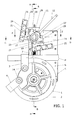
- Figure 1 shows a top plan view of the bending machine according to the present invention in an initial phase of the bending operation.
- the bending machine is of the matrix and countermatrix type. It comprises a roller-shaped matrix 1 provided with a partial circumferential groove 2, best shown in Figure 2 that is a side view being partially sectioned along the lines B-B in the top view of Figure 1 .
- the partial circumferential groove 2 is interrupted at its two ends, where respective retaining means 3, 4 is provided.
- Such retaining means 3, 4 has substantially a U-shape, the sides of the U-shape being joined at free ends thereof by a pivot 34 passing through the matrix 1.
- the matrix 1 is driven by a shaft 0 of a motor not shown in the figures.
- a casing 5 of the same bending machine is partially shown only in its upper part 6.
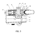
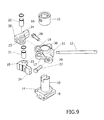
- Made on the upper part 6 of the casing 5 is a guide 7 suitable for sliding a slide 8 better shown in the side views of Figures 3 and 5 , which are partially cross-sectioned according to the lines F-F and H-H in Figure 1 , as well as in Figure 9 which is an exploded perspective view of a countermatrix support member.
- the slide 8 advances by means of a screw/nut screw coupling that is actuated by a handwheel 9 as shown in Figures 1 , 2 , 3 , 6 , 7 , and 8 , Figures 1 , 6 being top plan views of the bending machine in Figure 1 in initial and final moments of a counterclockwise bending operation, i.e. to left-hand, and Figures 7 and 8 in initial and final moments in a clockwise bending operation, i.e. to right-hand.
- the slide 8 extends upwards in a columnar element 10 best shown in Figures 2 , 3 , 5 , and 9 .
- Concentrically sleeve mounted to the columnar element 10 is a turret 11, that can rotate on the slide 8 if it is operated by a rod 12 connected to the turret 11.
- the turret 11, as shown in Figure 4 has at the bottom a pair of abutment elements 13 cooperating with a similar pair of abutment elements 14 formed on the slide 8. In this way, the turret 11 can rotate in a given arc of rotation on the slide 8.
- the turret 11 is locked on the top in order to prevent its slippage from the columnar element 10 by an abutment ring 15 arranged for a diametrical pin passing through the hole 16, as shown in particular in Figures 3 and 9 .
- the turret 11 has a pair of arms 17, 18 ( Figures 3 , 2 , 9 ) on each of which a countermatrix support member 19, 20 is pivotally mounted, each arm 17, 18 being connected to the respective countermatrix support member 19, 20 by means of a pin denoted as 21 and 22 respectively ( Figures 3 , 2 and 9 ).
- the countermatrix support members 19, 20 have an elongated shape.
- Each countermatrix support member 19, 20 has a protuberance 23 provided with a through hole for receiving the pins 21, 22, and a narrower portion 24 adapted to be connected to a countermatrix 25 and 26, respectively, to support it.
- the countermatrix support members 19, 20 being pivoted on the turret 11 are rotatable in an arc limited by a respective counteracting adjustable element 27, 28 that is threadedly coupled with related bored protrusions 29, 30 of the turret 11.
- Shown in Figure 1 is an elongated piece P to be bent that is inserted in the groove 2 of the matrix 1 and retained by retaining means 3 in the matrix 1 itself.
- the elongated piece P is ready to be counterclockwise bent, i.e. to left hand.
- the turret 11 is rotated to right hand by the rod 12 fully shown in Figure 1 , and a lower abutment element 13 thereof engages a corresponding abutment element 14 of the slide 8 ( Figure 4 ).
- the counteracting adjustable element 27 that limits the arc of rotation of the countermatrix support member 19, is in general completely screwed in the bored protrusion 29 ( Figure 1 ).
- the slide 8 is approached to the matrix 1 by the handwheel 9 ( Figure 1 ).
- the countermatrix 25 is brought in contact with the elongated piece P.
- the bending machine begins to bend to left hand ( Figure 6 ).
- the countermatrix 25 is initially moved away from the matrix 1, by simply rotating the shaft 0 in a direction opposite to the bending direction, by a sufficient angle, for example 10 degrees or less. Later, the countermatrix 25 is completely separated from the elongated piece P by rotating the turret 11 by the lever 12. At this point, by further rotating the shaft 0 to right hand, the matrix 1 is rotated in order to obtain the separation of the bent elongated piece P from the matrix 1.
- the elongated piece P to be bent is inserted in the groove 2 of the matrix 1 and retained in the retaining means of the matrix 1 itself.
- the elongated piece P is ready to be clockwise bent, i.e. to right hand.
- the turret 11 is rotated by the rod 12 fully to left hand, and its lower abutment element is counterclockwise rotated to engage the corresponding abutment element of the slide.
- the description of the adjustment of the counteracting adjustable element 28 is not repeated, being similar to that previously described.
- the slide 8 is approached to the matrix 1 by the handwheel 9 ( Figure 7 ).
- the countermatrix 26 is brought in contact with the elongated piece P.
- the bending machine begins to bend to right hand ( Figure 8 ).
- the countermatrix 26 is moved away from the matrix 1, by simply rotating the shaft 0 in a direction opposite to the bending direction, by a sufficient angle, for example 10 degrees or less, as already described for bending the elongated piece P to left hand.
- the countermatrix 26 is completely separated from the elongated P by rotating the turret 11 by the lever 12.
- the matrix 1 is rotated in order to obtain the separation of the bent elongated piece P from the matrix 1.
- Both right- and left-hand bending operations can be performed while maintaining the same position of the slide 8, and by rotating the turret 11 in the respective positions determined by the double pair of abutment elements 13 and 14.
- the matrix 1 remains mounted to the shaft 0 that is rotated to its initial positions shown in Figures 1 and 7 .
- the bending machine according to the invention allows the bending direction of an elongated piece P to be reversed simply and quickly, without the necessity of a removal of the matrix or any modification of the bending machine.
- Figure 10 is a top plan view of a variant of the matrix indicated as 31, which is different from that shown in the bending machine of the previous figures 1 to 9 .
- the rest of the bending machine is not represented as it is identical to that represented in those figures.
- an elongated element P is engaged to the matrix 31 at the beginning of a counterclockwise bending phase, i.e. to left hand.
- the matrix 31 has only one retaining means 32 for locking the elongated piece P in the vicinity of each of the two ends of the partial circumferential groove 2 of the matrix 1.
- the retaining means 32 is U-shaped, as best seen in Figure 11 , which is an exploded perspective view of the variant of matrix in Figure 10 .
- the retaining means 32 has sides 35, 36 that are provided in the vicinity of their free ends of through holes 37, 37, through which a pivot 33 can be inserted.
- the matrix 31 is provided with a hole 38 having an axis y1 parallel to the axis y of the shaft 0 of the motor.
- the axis yl of the hole 38 in the matrix 31 is equidistant between the two ends of the partial circumferential groove 2 of the matrix 31, which are indicated as 39, 40 in Figure 11 .
- the retaining means 32 is able to retain the elongated piece P for both counterclockwise bending the elongated piece P, as shown in Figure 10 , and clockwise bending it as shown in Figures 12.a-12.g , which are a plurality of top plan views of the variant of matrix in Figure 10 in successive phases of clockwise bending an elongated piece, i.e. to right-hand.
- Figures 12.a-12.g clearly show that a matrix 31 being provided with only one retaining means 32 of the elongated piece P allows its curvature by an angle greater than 180 degrees with an easy extraction of the elongated piece P at the end of the operation.
- Figure 12.a a view similar to that of Figure 10 is shown in Figure 12.a , but for clockwise bending.
- a first bending phase is shown in Figure 12.b , and, as shown in Figure 12.c , a curvature of more than 180 degrees is obtained.
- the retaining means 32 is extracted from the matrix 31; in Figure 12.e-12.g the bent elongated piece P is separated from the groove, turned upside down and removed from the matrix 31. This series of steps is valid also for the matrix having two retaining means, as previous described and illustrated in Figures 1 to 9 .
- the matrix 31 as a variant of the matrix 1 is more economic in its manufacture and has a smaller number of pieces with respect to matrix 1.
Landscapes
- Engineering & Computer Science (AREA)
- Mechanical Engineering (AREA)
- Bending Of Plates, Rods, And Pipes (AREA)
Priority Applications (9)
| Application Number | Priority Date | Filing Date | Title |
|---|---|---|---|
| PL14425014T PL2799158T3 (pl) | 2013-05-02 | 2014-02-13 | Giętarka typu z matrycą i kontrmatrycą do prawostronnego i lewostronnego gięcia podłużnego elementu |
| CA2850846A CA2850846C (en) | 2013-05-02 | 2014-04-28 | Die and counter-die type bending machine for right-hand and left-hand bending an elongated piece |
| RU2014117617/02A RU2569616C1 (ru) | 2013-05-02 | 2014-04-29 | Гибочный станок с матрицей и контрматрицей для правосторонней и левосторонней гибки удлиненной детали |
| MX2014005230A MX357439B (es) | 2013-05-02 | 2014-04-30 | Maquina dobladora del tipo de matriz y contramatriz para doblar hacia la derecha y hacia la izquierda una pieza alargada. |
| BR102014010400A BR102014010400A2 (pt) | 2013-05-02 | 2014-04-30 | máquina de dobragem do tipo molde e contramolde para dobrar para a direita e para a esquerda uma peça alongada |
| US14/267,047 US9878361B2 (en) | 2013-05-02 | 2014-05-01 | Die and counter-die type bending machine for right-hand and left-hand bending an elongated piece |
| JP2014094499A JP5889952B2 (ja) | 2013-05-02 | 2014-05-01 | 細長いピースを右回り及び左回りに曲げるためのダイ及びカウンターダイ型の曲げ機 |
| KR1020140053266A KR101636684B1 (ko) | 2013-05-02 | 2014-05-02 | 긴 가공물을 우측 및 좌측으로 굽힘 가공하기 위한 금형 및 상대 금형 방식의 벤딩 머신 |
| CN201410246716.XA CN104289566B (zh) | 2013-05-02 | 2014-05-04 | 用于向右和向左弯曲细长工件的模具加对立模具型的弯曲机 |
Applications Claiming Priority (1)
| Application Number | Priority Date | Filing Date | Title |
|---|---|---|---|
| IT000259A ITRM20130259A1 (it) | 2013-05-02 | 2013-05-02 | Macchina curvatrice del tipo a matrice e contromatrice per curvare a destra e a sinistra un pezzo allungato |
Publications (2)
| Publication Number | Publication Date |
|---|---|
| EP2799158A1 true EP2799158A1 (de) | 2014-11-05 |
| EP2799158B1 EP2799158B1 (de) | 2015-09-30 |
Family
ID=48579360
Family Applications (1)
| Application Number | Title | Priority Date | Filing Date |
|---|---|---|---|
| EP14425014.9A Active EP2799158B1 (de) | 2013-05-02 | 2014-02-13 | Biegemaschine mit Stempel und Gegenhalterstempel zum rechts und links Biegen eines länglichen Körpers |
Country Status (13)
| Country | Link |
|---|---|
| US (1) | US9878361B2 (de) |
| EP (1) | EP2799158B1 (de) |
| JP (1) | JP5889952B2 (de) |
| KR (1) | KR101636684B1 (de) |
| CN (1) | CN104289566B (de) |
| BR (1) | BR102014010400A2 (de) |
| CA (1) | CA2850846C (de) |
| ES (1) | ES2561167T3 (de) |
| IT (1) | ITRM20130259A1 (de) |
| MX (1) | MX357439B (de) |
| PL (1) | PL2799158T3 (de) |
| PT (1) | PT2799158E (de) |
| RU (1) | RU2569616C1 (de) |
Cited By (4)
| Publication number | Priority date | Publication date | Assignee | Title |
|---|---|---|---|---|
| WO2016157022A1 (en) * | 2015-04-02 | 2016-10-06 | Massaro Libero Angelo | Multipurpose machine for bending metal tubes, both small and large |
| ITUB20153370A1 (it) * | 2015-09-03 | 2017-03-03 | C B C S R L | Slitta perfezionata per un apparato di piegatura per elementi tubolari allungati |
| ITUA20161931A1 (it) * | 2016-03-23 | 2017-09-23 | Crippa Spa | Dispositivo per la curvatura di un materiale filiforme |
| WO2020100048A1 (en) * | 2018-11-16 | 2020-05-22 | Cml International S.P.A. | Machine for bending an elongated workpiece without wrinkling |
Families Citing this family (9)
| Publication number | Priority date | Publication date | Assignee | Title |
|---|---|---|---|---|
| CN106493258A (zh) * | 2016-11-08 | 2017-03-15 | 周朝敬 | 一种用于电缆的角度弯曲装置及其使用方法 |
| DE102017117979A1 (de) | 2017-08-08 | 2019-02-14 | Wafios Aktiengesellschaft | Biegemaschine zum Biegen von stab- oder rohrförmigen Werkstücken |
| CN107913927B (zh) * | 2017-09-18 | 2024-05-03 | 浙江长兴和良智能装备有限公司 | 一种弯管机 |
| MX2020005903A (es) * | 2017-12-11 | 2020-08-20 | Cml Int S P A | Maquina dobladora de tubos rotatoria accionada hidraulicamente. |
| CN109500288B (zh) * | 2018-12-27 | 2024-02-13 | 上海建工五建集团有限公司 | 一种便携式钢筋弯折工具及其使用方法 |
| CN112742923B (zh) * | 2020-12-21 | 2023-04-18 | 河南质量工程职业学院 | 一种用于建筑施工的弯管装置及其使用方法 |
| CN113619087B (zh) * | 2021-07-07 | 2023-09-29 | 岳阳高澜节能装备制造有限公司 | 一种可防端口变形的管道折弯装置 |
| CN113523043B (zh) * | 2021-07-20 | 2022-12-02 | 中国建筑第八工程局有限公司 | 工件弯曲装置及工件弯曲方法 |
| CN114425576A (zh) * | 2021-12-24 | 2022-05-03 | 安徽扬天金塑新能源装备有限公司 | 一种多向折弯的弯管装置 |
Citations (8)
| Publication number | Priority date | Publication date | Assignee | Title |
|---|---|---|---|---|
| US2455138A (en) | 1946-08-16 | 1948-11-30 | George C H Perkins | Pivoted bender with reversible clamp and former |
| US3921424A (en) | 1974-09-18 | 1975-11-25 | Greenlee Bros & Co | Portable electric driven conduit bender |
| US4546632A (en) | 1982-04-14 | 1985-10-15 | Applied Power Inc. | Portable conduit bending apparatus |
| EP0168331A2 (de) | 1984-07-10 | 1986-01-15 | Eaton Leonard Picot S.A. | Maschine zum Biegen von Rohren, Stangen oder Profilen |
| EP0445081A2 (de) * | 1990-03-02 | 1991-09-04 | C.M.L. COSTRUZIONI MECCANICHE LIRI S.r.l. | Rohrbiegemaschine mit freitragendem Biegekopf mit austauschbarem Mehrzweckwerkzeug sowie programmierbar mit Hilfe einer Computereinheit |
| US5499521A (en) | 1994-03-08 | 1996-03-19 | Crawford Fitting Company | Tube bender apparatus |
| US6434993B1 (en) | 2001-01-30 | 2002-08-20 | Blm S.P.A. | Bending machine for bending threadlike material such as tubes, rods profiles or metal wire |
| US8220304B2 (en) | 2005-10-28 | 2012-07-17 | Numalliance | Machine for cambering, forming, folding or bending bars, wires or extruded shapes |
Family Cites Families (24)
| Publication number | Priority date | Publication date | Assignee | Title |
|---|---|---|---|---|
| GB311720A (en) * | 1928-02-15 | 1929-05-15 | James Ernest Jackson | Improvements in pipe-bending machines |
| US1919839A (en) * | 1930-03-02 | 1933-07-25 | Hilgers Franz | Pipe-bending machine |
| US2171907A (en) * | 1936-08-05 | 1939-09-05 | Imp Brass Mfg Co | Tube bender |
| US3236082A (en) * | 1961-07-24 | 1966-02-22 | Crawford Fitting Co | Tube bending tools |
| US3448602A (en) * | 1965-10-24 | 1969-06-10 | Parker Hannifin Corp | Hand held tube bender |
| DE2626202C2 (de) * | 1976-06-11 | 1992-10-29 | Rigobert Dipl.-Ing. 5000 Köln Schwarze | Rohrbiegemaschine |
| JPS6480836A (en) * | 1987-09-24 | 1989-03-27 | Kaneko Agricult Machinery | Moisture measuring instrument for sample grain |
| JPH02263521A (ja) * | 1989-04-05 | 1990-10-26 | Hitachi Ltd | パイプ曲げ装置 |
| DE4106230A1 (de) * | 1991-02-25 | 1992-08-27 | Hans Werner Klieme | Vorrichtung zum biegen von hohlprofilstangen |
| DE9316052U1 (de) * | 1993-10-21 | 1994-01-13 | Schwarze Rigobert | Rohrbiegemaschine |
| IT1294256B1 (it) * | 1997-08-29 | 1999-03-24 | Cml Costr Mecc Liri Srl | Macchina curvatrice universale a raggi fissi e a raggi variabili |
| JPH11138215A (ja) * | 1997-11-06 | 1999-05-25 | Yamamoto Suiatsu Kogyosho:Kk | パイプベンダー |
| JP4592843B2 (ja) * | 1999-08-23 | 2010-12-08 | 株式会社オプトン | 曲げ装置 |
| JP2004314222A (ja) * | 2003-04-15 | 2004-11-11 | Imao Corporation:Kk | クランプ装置 |
| ITRM20040402A1 (it) * | 2004-08-05 | 2004-11-05 | Cml Int Spa | Morsa per il bloccaggio di un elemento allungato da curvare su di una matrice di macchina curvatrice. |
| ITRM20050035A1 (it) * | 2005-01-25 | 2006-07-26 | Cml Int Spa | Testa di curvatura per macchina curvatrice. |
| TWI273935B (en) * | 2005-01-25 | 2007-02-21 | Cml Int Spa | Bending device for bending machine |
| ATE397501T1 (de) * | 2005-03-08 | 2008-06-15 | Wafios Ag | Biegevorrichtung für stab- und rohrförmige werkstücke und faltenglätteranordnung |
| US7100414B1 (en) * | 2005-09-16 | 2006-09-05 | Mckay Acquisition, Inc. | Adjustable cam assembly for mounting a pressure die to a pipe bending machine |
| US7380430B1 (en) * | 2007-03-16 | 2008-06-03 | Christopher J. Rusch | Rotary draw tube bender |
| ITRM20070483A1 (it) * | 2007-09-17 | 2009-03-18 | Cml Int Spa | Macchina curvatubi con anima avente una struttura portante particolarmente resistente alle sollecitazioni di loavorazione |
| IT1391476B1 (it) * | 2008-10-28 | 2011-12-23 | Cml Int Spa | Macchina curvatubi con trasmissione perfezionata del moto alla matrice |
| ATE528082T1 (de) * | 2009-01-16 | 2011-10-15 | Wafios Ag | Rotationszugbiegewerkzeug mit exzenterklemmung |
| CN102601183A (zh) * | 2012-03-19 | 2012-07-25 | 昆山长运电子工业有限公司 | 多角度多直径工件折弯装置 |
-
2013
- 2013-05-02 IT IT000259A patent/ITRM20130259A1/it unknown
-
2014
- 2014-02-13 PL PL14425014T patent/PL2799158T3/pl unknown
- 2014-02-13 EP EP14425014.9A patent/EP2799158B1/de active Active
- 2014-02-13 PT PT144250149T patent/PT2799158E/pt unknown
- 2014-02-13 ES ES14425014.9T patent/ES2561167T3/es active Active
- 2014-04-28 CA CA2850846A patent/CA2850846C/en active Active
- 2014-04-29 RU RU2014117617/02A patent/RU2569616C1/ru active IP Right Revival
- 2014-04-30 BR BR102014010400A patent/BR102014010400A2/pt not_active Application Discontinuation
- 2014-04-30 MX MX2014005230A patent/MX357439B/es active IP Right Grant
- 2014-05-01 US US14/267,047 patent/US9878361B2/en active Active - Reinstated
- 2014-05-01 JP JP2014094499A patent/JP5889952B2/ja active Active
- 2014-05-02 KR KR1020140053266A patent/KR101636684B1/ko active IP Right Grant
- 2014-05-04 CN CN201410246716.XA patent/CN104289566B/zh active Active
Patent Citations (8)
| Publication number | Priority date | Publication date | Assignee | Title |
|---|---|---|---|---|
| US2455138A (en) | 1946-08-16 | 1948-11-30 | George C H Perkins | Pivoted bender with reversible clamp and former |
| US3921424A (en) | 1974-09-18 | 1975-11-25 | Greenlee Bros & Co | Portable electric driven conduit bender |
| US4546632A (en) | 1982-04-14 | 1985-10-15 | Applied Power Inc. | Portable conduit bending apparatus |
| EP0168331A2 (de) | 1984-07-10 | 1986-01-15 | Eaton Leonard Picot S.A. | Maschine zum Biegen von Rohren, Stangen oder Profilen |
| EP0445081A2 (de) * | 1990-03-02 | 1991-09-04 | C.M.L. COSTRUZIONI MECCANICHE LIRI S.r.l. | Rohrbiegemaschine mit freitragendem Biegekopf mit austauschbarem Mehrzweckwerkzeug sowie programmierbar mit Hilfe einer Computereinheit |
| US5499521A (en) | 1994-03-08 | 1996-03-19 | Crawford Fitting Company | Tube bender apparatus |
| US6434993B1 (en) | 2001-01-30 | 2002-08-20 | Blm S.P.A. | Bending machine for bending threadlike material such as tubes, rods profiles or metal wire |
| US8220304B2 (en) | 2005-10-28 | 2012-07-17 | Numalliance | Machine for cambering, forming, folding or bending bars, wires or extruded shapes |
Cited By (8)
| Publication number | Priority date | Publication date | Assignee | Title |
|---|---|---|---|---|
| WO2016157022A1 (en) * | 2015-04-02 | 2016-10-06 | Massaro Libero Angelo | Multipurpose machine for bending metal tubes, both small and large |
| US20180078984A1 (en) * | 2015-04-02 | 2018-03-22 | Libero Angelo MASSARO | Multipurpose machine for bending metal tubes, both small and large |
| ITUB20153370A1 (it) * | 2015-09-03 | 2017-03-03 | C B C S R L | Slitta perfezionata per un apparato di piegatura per elementi tubolari allungati |
| EP3141311A1 (de) * | 2015-09-03 | 2017-03-15 | C.B.C. S.r.l. | Verbesserter schlitten für eine biegemaschine zum biegen von länglichen rohrförmigen elementen |
| ITUA20161931A1 (it) * | 2016-03-23 | 2017-09-23 | Crippa Spa | Dispositivo per la curvatura di un materiale filiforme |
| EP3228397A1 (de) * | 2016-03-23 | 2017-10-11 | Crippa S.P.A. | Vorrichtung zum biegen eines drahtähnlichen materials |
| WO2020100048A1 (en) * | 2018-11-16 | 2020-05-22 | Cml International S.P.A. | Machine for bending an elongated workpiece without wrinkling |
| US11745244B2 (en) | 2018-11-16 | 2023-09-05 | Cml International S.P.A. | Machine for bending an elongated workpiece without wrinkling |
Also Published As
| Publication number | Publication date |
|---|---|
| US20140326033A1 (en) | 2014-11-06 |
| BR102014010400A2 (pt) | 2015-12-29 |
| KR20140131282A (ko) | 2014-11-12 |
| JP2014223673A (ja) | 2014-12-04 |
| KR101636684B1 (ko) | 2016-07-07 |
| RU2014117617A (ru) | 2015-11-10 |
| MX357439B (es) | 2018-07-10 |
| US9878361B2 (en) | 2018-01-30 |
| MX2014005230A (es) | 2015-04-29 |
| PL2799158T3 (pl) | 2016-08-31 |
| PT2799158E (pt) | 2016-01-27 |
| CA2850846C (en) | 2018-06-12 |
| EP2799158B1 (de) | 2015-09-30 |
| ES2561167T3 (es) | 2016-02-24 |
| CN104289566B (zh) | 2016-09-07 |
| JP5889952B2 (ja) | 2016-03-22 |
| RU2569616C1 (ru) | 2015-11-27 |
| CN104289566A (zh) | 2015-01-21 |
| CA2850846A1 (en) | 2014-11-02 |
| ITRM20130259A1 (it) | 2014-11-03 |
Similar Documents
| Publication | Publication Date | Title |
|---|---|---|
| EP2799158B1 (de) | Biegemaschine mit Stempel und Gegenhalterstempel zum rechts und links Biegen eines länglichen Körpers | |
| US3040800A (en) | Tube flaring tool | |
| EP3177414B1 (de) | Biegekopf, insbesondere für eine automatische biegemaschine | |
| CN208083266U (zh) | 一种钢筋的折弯冲压模具 | |
| US10189069B1 (en) | Portable tube bender | |
| EP3315331B1 (de) | Reifenwechselmaschine | |
| EP3315251B1 (de) | Elektrospindel für automatischen werkzeugwechsel und bearbeitungszentrum mit automatischer werkzeugwechselvorrichtung | |
| EP2977324B1 (de) | Abgabevorrichtung, abgabeverfahren, abdeckvorrichtung und verfahren zum abdecken | |
| EP3041638B1 (de) | Positioniereinrichtung für rohre | |
| KR101895320B1 (ko) | 파이프 밴딩장치 | |
| JP5894136B2 (ja) | 加工ユニットおよび加工装置 | |
| JP6159452B2 (ja) | ワイヤ曲げ装置 | |
| RU2670593C2 (ru) | Узел для разбортовки | |
| EP2014382A1 (de) | Rohrbiegemaschine | |
| EP1579930B1 (de) | Maschine zum Biegen von Stangen | |
| US2569544A (en) | Portable bending machine | |
| JP2008036675A (ja) | 曲げ加工装置 | |
| EP2982455A1 (de) | Vorrichtung und verfahren zum rohrbiegen | |
| CN104999401A (zh) | 螺旋快速棘轮扳手 | |
| CN107671206B (zh) | 钢筋调直器 | |
| CN207642191U (zh) | 一种液压钢筋弯曲机 | |
| CN210966500U (zh) | 一种折弯机折弯装置 | |
| JP6682359B2 (ja) | 線材曲げ装置 |
Legal Events
| Date | Code | Title | Description |
|---|---|---|---|
| PUAI | Public reference made under article 153(3) epc to a published international application that has entered the european phase |
Free format text: ORIGINAL CODE: 0009012 |
|
| 17P | Request for examination filed |
Effective date: 20140213 |
|
| AK | Designated contracting states |
Kind code of ref document: A1 Designated state(s): AL AT BE BG CH CY CZ DE DK EE ES FI FR GB GR HR HU IE IS IT LI LT LU LV MC MK MT NL NO PL PT RO RS SE SI SK SM TR |
|
| AX | Request for extension of the european patent |
Extension state: BA ME |
|
| R17P | Request for examination filed (corrected) |
Effective date: 20141009 |
|
| RBV | Designated contracting states (corrected) |
Designated state(s): AL AT BE BG CH CY CZ DE DK EE ES FI FR GB GR HR HU IE IS IT LI LT LU LV MC MK MT NL NO PL PT RO RS SE SI SK SM TR |
|
| GRAP | Despatch of communication of intention to grant a patent |
Free format text: ORIGINAL CODE: EPIDOSNIGR1 |
|
| RIC1 | Information provided on ipc code assigned before grant |
Ipc: B21D 7/024 20060101AFI20150409BHEP |
|
| INTG | Intention to grant announced |
Effective date: 20150424 |
|
| GRAS | Grant fee paid |
Free format text: ORIGINAL CODE: EPIDOSNIGR3 |
|
| GRAA | (expected) grant |
Free format text: ORIGINAL CODE: 0009210 |
|
| AK | Designated contracting states |
Kind code of ref document: B1 Designated state(s): AL AT BE BG CH CY CZ DE DK EE ES FI FR GB GR HR HU IE IS IT LI LT LU LV MC MK MT NL NO PL PT RO RS SE SI SK SM TR |
|
| REG | Reference to a national code |
Ref country code: CH Ref legal event code: EP Ref country code: GB Ref legal event code: FG4D |
|
| REG | Reference to a national code |
Ref country code: AT Ref legal event code: REF Ref document number: 752086 Country of ref document: AT Kind code of ref document: T Effective date: 20151015 |
|
| REG | Reference to a national code |
Ref country code: IE Ref legal event code: FG4D |
|
| REG | Reference to a national code |
Ref country code: DE Ref legal event code: R096 Ref document number: 602014000289 Country of ref document: DE |
|
| REG | Reference to a national code |
Ref country code: PT Ref legal event code: SC4A Free format text: AVAILABILITY OF NATIONAL TRANSLATION Effective date: 20151228 |
|
| PG25 | Lapsed in a contracting state [announced via postgrant information from national office to epo] |
Ref country code: GR Free format text: LAPSE BECAUSE OF FAILURE TO SUBMIT A TRANSLATION OF THE DESCRIPTION OR TO PAY THE FEE WITHIN THE PRESCRIBED TIME-LIMIT Effective date: 20151231 Ref country code: LT Free format text: LAPSE BECAUSE OF FAILURE TO SUBMIT A TRANSLATION OF THE DESCRIPTION OR TO PAY THE FEE WITHIN THE PRESCRIBED TIME-LIMIT Effective date: 20150930 Ref country code: FI Free format text: LAPSE BECAUSE OF FAILURE TO SUBMIT A TRANSLATION OF THE DESCRIPTION OR TO PAY THE FEE WITHIN THE PRESCRIBED TIME-LIMIT Effective date: 20150930 Ref country code: NO Free format text: LAPSE BECAUSE OF FAILURE TO SUBMIT A TRANSLATION OF THE DESCRIPTION OR TO PAY THE FEE WITHIN THE PRESCRIBED TIME-LIMIT Effective date: 20151230 Ref country code: LV Free format text: LAPSE BECAUSE OF FAILURE TO SUBMIT A TRANSLATION OF THE DESCRIPTION OR TO PAY THE FEE WITHIN THE PRESCRIBED TIME-LIMIT Effective date: 20150930 |
|
| REG | Reference to a national code |
Ref country code: NL Ref legal event code: MP Effective date: 20150930 |
|
| REG | Reference to a national code |
Ref country code: LT Ref legal event code: MG4D |
|
| REG | Reference to a national code |
Ref country code: AT Ref legal event code: MK05 Ref document number: 752086 Country of ref document: AT Kind code of ref document: T Effective date: 20150930 |
|
| REG | Reference to a national code |
Ref country code: ES Ref legal event code: FG2A Ref document number: 2561167 Country of ref document: ES Kind code of ref document: T3 Effective date: 20160224 |
|
| PG25 | Lapsed in a contracting state [announced via postgrant information from national office to epo] |
Ref country code: RS Free format text: LAPSE BECAUSE OF FAILURE TO SUBMIT A TRANSLATION OF THE DESCRIPTION OR TO PAY THE FEE WITHIN THE PRESCRIBED TIME-LIMIT Effective date: 20150930 Ref country code: HR Free format text: LAPSE BECAUSE OF FAILURE TO SUBMIT A TRANSLATION OF THE DESCRIPTION OR TO PAY THE FEE WITHIN THE PRESCRIBED TIME-LIMIT Effective date: 20150930 Ref country code: SE Free format text: LAPSE BECAUSE OF FAILURE TO SUBMIT A TRANSLATION OF THE DESCRIPTION OR TO PAY THE FEE WITHIN THE PRESCRIBED TIME-LIMIT Effective date: 20150930 |
|
| REG | Reference to a national code |
Ref country code: FR Ref legal event code: PLFP Year of fee payment: 3 |
|
| PG25 | Lapsed in a contracting state [announced via postgrant information from national office to epo] |
Ref country code: EE Free format text: LAPSE BECAUSE OF FAILURE TO SUBMIT A TRANSLATION OF THE DESCRIPTION OR TO PAY THE FEE WITHIN THE PRESCRIBED TIME-LIMIT Effective date: 20150930 Ref country code: IS Free format text: LAPSE BECAUSE OF FAILURE TO SUBMIT A TRANSLATION OF THE DESCRIPTION OR TO PAY THE FEE WITHIN THE PRESCRIBED TIME-LIMIT Effective date: 20160130 Ref country code: IT Free format text: LAPSE BECAUSE OF FAILURE TO SUBMIT A TRANSLATION OF THE DESCRIPTION OR TO PAY THE FEE WITHIN THE PRESCRIBED TIME-LIMIT Effective date: 20150930 Ref country code: CZ Free format text: LAPSE BECAUSE OF FAILURE TO SUBMIT A TRANSLATION OF THE DESCRIPTION OR TO PAY THE FEE WITHIN THE PRESCRIBED TIME-LIMIT Effective date: 20150930 Ref country code: NL Free format text: LAPSE BECAUSE OF FAILURE TO SUBMIT A TRANSLATION OF THE DESCRIPTION OR TO PAY THE FEE WITHIN THE PRESCRIBED TIME-LIMIT Effective date: 20150930 Ref country code: SK Free format text: LAPSE BECAUSE OF FAILURE TO SUBMIT A TRANSLATION OF THE DESCRIPTION OR TO PAY THE FEE WITHIN THE PRESCRIBED TIME-LIMIT Effective date: 20150930 |
|
| PG25 | Lapsed in a contracting state [announced via postgrant information from national office to epo] |
Ref country code: AT Free format text: LAPSE BECAUSE OF FAILURE TO SUBMIT A TRANSLATION OF THE DESCRIPTION OR TO PAY THE FEE WITHIN THE PRESCRIBED TIME-LIMIT Effective date: 20150930 Ref country code: BE Free format text: LAPSE BECAUSE OF NON-PAYMENT OF DUE FEES Effective date: 20160229 Ref country code: RO Free format text: LAPSE BECAUSE OF FAILURE TO SUBMIT A TRANSLATION OF THE DESCRIPTION OR TO PAY THE FEE WITHIN THE PRESCRIBED TIME-LIMIT Effective date: 20150930 |
|
| REG | Reference to a national code |
Ref country code: DE Ref legal event code: R097 Ref document number: 602014000289 Country of ref document: DE |
|
| PLBE | No opposition filed within time limit |
Free format text: ORIGINAL CODE: 0009261 |
|
| STAA | Information on the status of an ep patent application or granted ep patent |
Free format text: STATUS: NO OPPOSITION FILED WITHIN TIME LIMIT |
|
| PG25 | Lapsed in a contracting state [announced via postgrant information from national office to epo] |
Ref country code: DK Free format text: LAPSE BECAUSE OF FAILURE TO SUBMIT A TRANSLATION OF THE DESCRIPTION OR TO PAY THE FEE WITHIN THE PRESCRIBED TIME-LIMIT Effective date: 20150930 |
|
| REG | Reference to a national code |
Ref country code: DE Ref legal event code: R119 Ref document number: 602014000289 Country of ref document: DE |
|
| REG | Reference to a national code |
Ref country code: DE Ref legal event code: R073 Ref document number: 602014000289 Country of ref document: DE |
|
| 26N | No opposition filed |
Effective date: 20160701 |
|
| PG25 | Lapsed in a contracting state [announced via postgrant information from national office to epo] |
Ref country code: LU Free format text: LAPSE BECAUSE OF FAILURE TO SUBMIT A TRANSLATION OF THE DESCRIPTION OR TO PAY THE FEE WITHIN THE PRESCRIBED TIME-LIMIT Effective date: 20160213 Ref country code: MC Free format text: LAPSE BECAUSE OF FAILURE TO SUBMIT A TRANSLATION OF THE DESCRIPTION OR TO PAY THE FEE WITHIN THE PRESCRIBED TIME-LIMIT Effective date: 20150930 |
|
| PG25 | Lapsed in a contracting state [announced via postgrant information from national office to epo] |
Ref country code: SI Free format text: LAPSE BECAUSE OF FAILURE TO SUBMIT A TRANSLATION OF THE DESCRIPTION OR TO PAY THE FEE WITHIN THE PRESCRIBED TIME-LIMIT Effective date: 20150930 |
|
| REG | Reference to a national code |
Ref country code: IE Ref legal event code: MM4A |
|
| PG25 | Lapsed in a contracting state [announced via postgrant information from national office to epo] |
Ref country code: BE Free format text: LAPSE BECAUSE OF FAILURE TO SUBMIT A TRANSLATION OF THE DESCRIPTION OR TO PAY THE FEE WITHIN THE PRESCRIBED TIME-LIMIT Effective date: 20150930 |
|
| PG25 | Lapsed in a contracting state [announced via postgrant information from national office to epo] |
Ref country code: IE Free format text: LAPSE BECAUSE OF NON-PAYMENT OF DUE FEES Effective date: 20160213 Ref country code: DE Free format text: LAPSE BECAUSE OF NON-PAYMENT OF DUE FEES Effective date: 20160901 |
|
| PG25 | Lapsed in a contracting state [announced via postgrant information from national office to epo] |
Ref country code: PT Free format text: LAPSE BECAUSE OF NON-PAYMENT OF DUE FEES Effective date: 20161114 |
|
| REG | Reference to a national code |
Ref country code: FR Ref legal event code: PLFP Year of fee payment: 4 |
|
| REG | Reference to a national code |
Ref country code: DE Ref legal event code: R124 Ref document number: 602014000289 Country of ref document: DE |
|
| PG25 | Lapsed in a contracting state [announced via postgrant information from national office to epo] |
Ref country code: MT Free format text: LAPSE BECAUSE OF FAILURE TO SUBMIT A TRANSLATION OF THE DESCRIPTION OR TO PAY THE FEE WITHIN THE PRESCRIBED TIME-LIMIT Effective date: 20150930 |
|
| REG | Reference to a national code |
Ref country code: CH Ref legal event code: PL |
|
| PG25 | Lapsed in a contracting state [announced via postgrant information from national office to epo] |
Ref country code: LI Free format text: LAPSE BECAUSE OF NON-PAYMENT OF DUE FEES Effective date: 20170228 Ref country code: CH Free format text: LAPSE BECAUSE OF NON-PAYMENT OF DUE FEES Effective date: 20170228 |
|
| PG25 | Lapsed in a contracting state [announced via postgrant information from national office to epo] |
Ref country code: SM Free format text: LAPSE BECAUSE OF FAILURE TO SUBMIT A TRANSLATION OF THE DESCRIPTION OR TO PAY THE FEE WITHIN THE PRESCRIBED TIME-LIMIT Effective date: 20150930 Ref country code: HU Free format text: LAPSE BECAUSE OF FAILURE TO SUBMIT A TRANSLATION OF THE DESCRIPTION OR TO PAY THE FEE WITHIN THE PRESCRIBED TIME-LIMIT; INVALID AB INITIO Effective date: 20140213 |
|
| PG25 | Lapsed in a contracting state [announced via postgrant information from national office to epo] |
Ref country code: MK Free format text: LAPSE BECAUSE OF FAILURE TO SUBMIT A TRANSLATION OF THE DESCRIPTION OR TO PAY THE FEE WITHIN THE PRESCRIBED TIME-LIMIT Effective date: 20150930 Ref country code: MT Free format text: LAPSE BECAUSE OF FAILURE TO SUBMIT A TRANSLATION OF THE DESCRIPTION OR TO PAY THE FEE WITHIN THE PRESCRIBED TIME-LIMIT Effective date: 20160229 Ref country code: CY Free format text: LAPSE BECAUSE OF FAILURE TO SUBMIT A TRANSLATION OF THE DESCRIPTION OR TO PAY THE FEE WITHIN THE PRESCRIBED TIME-LIMIT Effective date: 20150930 |
|
| REG | Reference to a national code |
Ref country code: FR Ref legal event code: PLFP Year of fee payment: 5 |
|
| PG25 | Lapsed in a contracting state [announced via postgrant information from national office to epo] |
Ref country code: BG Free format text: LAPSE BECAUSE OF FAILURE TO SUBMIT A TRANSLATION OF THE DESCRIPTION OR TO PAY THE FEE WITHIN THE PRESCRIBED TIME-LIMIT Effective date: 20150930 |
|
| PG25 | Lapsed in a contracting state [announced via postgrant information from national office to epo] |
Ref country code: AL Free format text: LAPSE BECAUSE OF FAILURE TO SUBMIT A TRANSLATION OF THE DESCRIPTION OR TO PAY THE FEE WITHIN THE PRESCRIBED TIME-LIMIT Effective date: 20150930 |
|
| PGFP | Annual fee paid to national office [announced via postgrant information from national office to epo] |
Ref country code: TR Payment date: 20190213 Year of fee payment: 6 |
|
| PGFP | Annual fee paid to national office [announced via postgrant information from national office to epo] |
Ref country code: PL Payment date: 20210215 Year of fee payment: 8 |
|
| PG25 | Lapsed in a contracting state [announced via postgrant information from national office to epo] |
Ref country code: TR Free format text: LAPSE BECAUSE OF NON-PAYMENT OF DUE FEES Effective date: 20200213 |
|
| PGFP | Annual fee paid to national office [announced via postgrant information from national office to epo] |
Ref country code: FR Payment date: 20230227 Year of fee payment: 10 |
|
| PGFP | Annual fee paid to national office [announced via postgrant information from national office to epo] |
Ref country code: PT Payment date: 20230301 Year of fee payment: 10 |
|
| PGFP | Annual fee paid to national office [announced via postgrant information from national office to epo] |
Ref country code: ES Payment date: 20230503 Year of fee payment: 10 |
|
| PGFP | Annual fee paid to national office [announced via postgrant information from national office to epo] |
Ref country code: GB Payment date: 20240122 Year of fee payment: 11 |