EP0319400A1 - Rohrleitungsbiegegerät und Verfahren zum Herstellen einer Rohrleitung mit geschweisstem Ansatzstück - Google Patents
Rohrleitungsbiegegerät und Verfahren zum Herstellen einer Rohrleitung mit geschweisstem Ansatzstück Download PDFInfo
- Publication number
- EP0319400A1 EP0319400A1 EP88403006A EP88403006A EP0319400A1 EP 0319400 A1 EP0319400 A1 EP 0319400A1 EP 88403006 A EP88403006 A EP 88403006A EP 88403006 A EP88403006 A EP 88403006A EP 0319400 A1 EP0319400 A1 EP 0319400A1
- Authority
- EP
- European Patent Office
- Prior art keywords
- bending
- pipe
- roller
- clamping jaw
- machine
- Prior art date
- Legal status (The legal status is an assumption and is not a legal conclusion. Google has not performed a legal analysis and makes no representation as to the accuracy of the status listed.)
- Withdrawn
Links
Images

Classifications
-
- B—PERFORMING OPERATIONS; TRANSPORTING
- B21—MECHANICAL METAL-WORKING WITHOUT ESSENTIALLY REMOVING MATERIAL; PUNCHING METAL
- B21D—WORKING OR PROCESSING OF SHEET METAL OR METAL TUBES, RODS OR PROFILES WITHOUT ESSENTIALLY REMOVING MATERIAL; PUNCHING METAL
- B21D7/00—Bending rods, profiles, or tubes
- B21D7/02—Bending rods, profiles, or tubes over a stationary forming member; by use of a swinging forming member or abutment
- B21D7/024—Bending rods, profiles, or tubes over a stationary forming member; by use of a swinging forming member or abutment by a swinging forming member
-
- B—PERFORMING OPERATIONS; TRANSPORTING
- B21—MECHANICAL METAL-WORKING WITHOUT ESSENTIALLY REMOVING MATERIAL; PUNCHING METAL
- B21D—WORKING OR PROCESSING OF SHEET METAL OR METAL TUBES, RODS OR PROFILES WITHOUT ESSENTIALLY REMOVING MATERIAL; PUNCHING METAL
- B21D7/00—Bending rods, profiles, or tubes
- B21D7/02—Bending rods, profiles, or tubes over a stationary forming member; by use of a swinging forming member or abutment
- B21D7/021—Construction of forming members having more than one groove
Definitions
- the present invention relates to a bending tool intended for carrying out pipe bending operations on a bending machine and it also relates to an associated method of manufacturing pipe.
- EP-A 0 168 331 describes a horizontal bending machine of this type equipped with its bending tool comprising a rotary forming roller of vertical axis, having an annular groove and supporting a first jaw, a second jaw carried by a bending arm mounted pivoting around said vertical axis and intended to ensure the tightening of the pipe to be bent opposite the first jaw and a horizontal strip, placed behind the jaws and providing guidance and support for the pipe.
- the rotation of the bending arm winds the tight pipe between the jaws in the groove of the forming roller.
- the rear end of the pipeline is pinched in a clamping mandrel capable of imposing rotations on the pipeline and of displacing it in the longitudinal direction by means of a carriage.
- the object of the invention is to obtain a bending tool suitable for carrying out successive pipe bending operations comprising a first bending operation at the end of the pipe having a short straight length, avoiding the drawbacks of known prior solutions and by allowing a modification of the operating flow of shaping of pipe previously applied.
- a bending tool of the aforementioned type and in accordance with the invention is characterized in that the bending roller comprises a removable element which is removed during a first bending operation at the end of a pipe, provided with a welded end piece and comprising a short length L for holding on a straight part and which is replaced for the following bending operations and that the clamping jaw comprises during said first bending operation an element having a flat face in contact with said end piece pipe and which is replaced during the following bending operations by a clamping jaw element having a semi-cylindrical groove cooperating with the pipe.
- the bending tool and the method of manufacturing pipes in accordance with the invention have significant advantages over the previously known means and methods.
- the welding operation as well as the associated operations, in particular the X-ray inspection are much easier in their implementation and the results improved by performing them on a straight tube instead of the be on a fully formed pipe.
- the quality of the parts and in particular the geometric tolerances are better respected by carrying out the bending operation at the final stage.
- the same tools with a single roller and a single clamping jaw can be used.
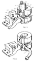
- the bending tool 1 shown in FIGS. 1 to 3 comprises a bending roller 2 and a support 3 secured to a bending arm 4.
- the bending tool 1 is mounted on a bending machine of a known type, not shown in the drawings.
- the roller 2 is placed on a vertical rotary axis of the bending head of the machine passing through its central bore 5 and the base 6 of the roller 2 rests on a plate of said bending head.
- An annular groove 7 is formed at mid-height on the external cylindrical surface 8 of the roller 2 and has a semicircular section.
- the roller 2 is integral with the bending arm 4.
- the roller 2 In line with the bending arm 4, the roller 2 has at its upper part a cutout providing a housing 9 on its external surface.
- a jaw part 10 secured to the roller 2 comprising a groove 10a at the level of the groove 7 of the roller 2 and which leaves a hollow portion 11 on the upper part of the roller 2.
- the clamping jaw 17 has a flat front face 19 which remains in contact with the end piece 13 and keeps it during bending so tighten the straight part L of the pipe end 12 against the g alet 2 and in particular in the groove 10a of the jaw 10. But no contact is established between said flat face 19 and the straight part of the pipe itself which is clamped in the housing 3a formed on the cooperating edge of the support 3, as shown in Figure 1a.
- the first bending operation using said bending tool 1 takes place as follows.
- the line 12 being placed on the tool 1 in the configuration shown in FIG. 1, the other end of the line 12 is pinched in a mandrel of the bending machine, not shown in the drawings.
- the support 3 of the clamping jaw 17 is also secured to a assembly, belonging to the bending machine not shown in the drawings, which carries the bending arm 4 and which comprises a means of translation of said support 3, such as a jack which brings the clamping jaw 17 towards the start of the operation roller 2 and discards it at the end of the operation.
- the bending program available on the bending machine is then started and the first bending is carried out, followed by a cycle stop.
- the centering tool 1 according to the invention thanks to the cooperation of said flat face 19 of the jaw 17 with the nozzle 13 of pipe only thus makes it possible to avoid, in a ramarchable manner, any marking and any deterioration of the straight part end of the pipe 12. At the same time, this tool remains usable for pipes of different diameters.
- the clamping jaw 17 with flat face 19 used for the first clamping is removed from the support 3 and replaced by a clamping jaw 117 also comprising an opening 118 for positioning on the axis 18 of the support 3 the front face of which has a groove 20 with a semi-circular section.
- the bending roller 2 is completed by a removable complementary element 21 which is placed in the recess 11 and comprises a handling button 22 at its upper part and on its rear face, a guide element 23 which is by example of a semi-cylindrical section and cooperates with a slide 24 of semi-circular section formed on the roller 2 in the bottom of the recess 11.
- the removable element 21 also includes a groove 25 of semi-circular section which completes the groove 7 of the roller 2.
- the bending tool and the method which have just been described can be used for pipes for which, depending on the applications and their various definition parameters, tube diameter and bending angle in particular, an internal mandrel must or does not must not be used during bending operations.
Applications Claiming Priority (2)
| Application Number | Priority Date | Filing Date | Title |
|---|---|---|---|
| FR8716699A FR2624038A1 (fr) | 1987-12-02 | 1987-12-02 | Outillage de cintrage de canalisations et procede de fabrication d'une canalisation a embout soude |
| FR8716699 | 1987-12-02 |
Publications (1)
| Publication Number | Publication Date |
|---|---|
| EP0319400A1 true EP0319400A1 (de) | 1989-06-07 |
Family
ID=9357375
Family Applications (1)
| Application Number | Title | Priority Date | Filing Date |
|---|---|---|---|
| EP88403006A Withdrawn EP0319400A1 (de) | 1987-12-02 | 1988-11-30 | Rohrleitungsbiegegerät und Verfahren zum Herstellen einer Rohrleitung mit geschweisstem Ansatzstück |
Country Status (3)
| Country | Link |
|---|---|
| US (1) | US4899567A (de) |
| EP (1) | EP0319400A1 (de) |
| FR (1) | FR2624038A1 (de) |
Cited By (3)
| Publication number | Priority date | Publication date | Assignee | Title |
|---|---|---|---|---|
| FR2758281A1 (fr) * | 1997-01-14 | 1998-07-17 | Robolix Sa | Machine a cintrer des tubes de faible diametre, notamment inferieurs a 10mm, predecoupes et presentant des systemes de raccord a chacune de leurs extremites, et tete de cintrage pour une telle machine |
| EP1767285B1 (de) * | 2005-09-21 | 2008-03-19 | Dipl.-Ing. H. Schulz HDS Hydraulic GmbH & Co. KG | Biegewerkzeug für Hydraulik-Bogenarmaturen |
| EP3181977A1 (de) * | 2015-12-18 | 2017-06-21 | Stelia Aerospace | Herstellungsverfahren einer kanalisation, gesamtheit einer kanalisation und eines verbindungsanschlusses |
Families Citing this family (5)
| Publication number | Priority date | Publication date | Assignee | Title |
|---|---|---|---|---|
| US6045033A (en) * | 1998-04-02 | 2000-04-04 | Tri-Clover, Inc. | Pipe connection and method |
| US6220069B1 (en) * | 2000-01-19 | 2001-04-24 | General Electric Company | Method and apparatus for bending tubing |
| US7076982B2 (en) * | 2004-01-09 | 2006-07-18 | Jeffrey & Connie Coop, Llc | Concentric bore bend die and clamp insert assembly |
| US7870773B2 (en) * | 2007-02-28 | 2011-01-18 | Tennine Corporation | Inserted wiper die for high-pressure tube-bending and method of using same |
| CN112045006B (zh) * | 2020-07-10 | 2022-02-15 | 张家港市昆仑管业有限公司 | 反旋螺旋管的弯制方法 |
Citations (5)
| Publication number | Priority date | Publication date | Assignee | Title |
|---|---|---|---|---|
| DE722076C (de) * | 1938-12-28 | 1942-06-29 | Fried Krupp Germaniawerft Ag | Klemmvorrichtung mit auswechselbaren, geraden und gebogenen Rohren angepassten Klemmbacken |
| US4083216A (en) * | 1977-05-16 | 1978-04-11 | Caterpillar Tractor Co. | Support pin for clamping die assembly |
| FR2530980A1 (fr) * | 1982-08-02 | 1984-02-03 | Eaton Leonard Corp | Cintreuse a courbures multiples |
| EP0168331A2 (de) * | 1984-07-10 | 1986-01-15 | Eaton Leonard Picot S.A. | Maschine zum Biegen von Rohren, Stangen oder Profilen |
| EP0245623A2 (de) * | 1986-05-14 | 1987-11-19 | Rigobert Dipl.-Ing. Schwarze | Rohrbiegemaschine |
Family Cites Families (6)
| Publication number | Priority date | Publication date | Assignee | Title |
|---|---|---|---|---|
| US1167538A (en) * | 1914-08-01 | 1916-01-11 | Locomotive Superheater Co | Pipe-bending die. |
| US2357006A (en) * | 1942-10-27 | 1944-08-29 | Cleveland Pneumatic Tool Co | Tube bending machine |
| DE1112381B (de) * | 1960-07-27 | 1961-08-03 | Peddinghaus Paul Ferd Fa | Biegevorrichtung fuer Betonstahl |
| US3394571A (en) * | 1966-04-14 | 1968-07-30 | William C. Rose | Conduit-bending machines |
| IT1137724B (it) * | 1981-07-10 | 1986-09-10 | Mec Montorfano Di Montorfano V | Unita' di curvatura per tubi e fili in metallo e procedimento di messa in esercizio dell'unita |
| EP0120336B2 (de) * | 1983-03-26 | 1991-10-09 | Rigobert Dipl.-Ing. Schwarze | Rohrbiegemaschine |
-
1987
- 1987-12-02 FR FR8716699A patent/FR2624038A1/fr not_active Withdrawn
-
1988
- 1988-11-28 US US07/276,475 patent/US4899567A/en not_active Expired - Fee Related
- 1988-11-30 EP EP88403006A patent/EP0319400A1/de not_active Withdrawn
Patent Citations (5)
| Publication number | Priority date | Publication date | Assignee | Title |
|---|---|---|---|---|
| DE722076C (de) * | 1938-12-28 | 1942-06-29 | Fried Krupp Germaniawerft Ag | Klemmvorrichtung mit auswechselbaren, geraden und gebogenen Rohren angepassten Klemmbacken |
| US4083216A (en) * | 1977-05-16 | 1978-04-11 | Caterpillar Tractor Co. | Support pin for clamping die assembly |
| FR2530980A1 (fr) * | 1982-08-02 | 1984-02-03 | Eaton Leonard Corp | Cintreuse a courbures multiples |
| EP0168331A2 (de) * | 1984-07-10 | 1986-01-15 | Eaton Leonard Picot S.A. | Maschine zum Biegen von Rohren, Stangen oder Profilen |
| EP0245623A2 (de) * | 1986-05-14 | 1987-11-19 | Rigobert Dipl.-Ing. Schwarze | Rohrbiegemaschine |
Cited By (7)
| Publication number | Priority date | Publication date | Assignee | Title |
|---|---|---|---|---|
| FR2758281A1 (fr) * | 1997-01-14 | 1998-07-17 | Robolix Sa | Machine a cintrer des tubes de faible diametre, notamment inferieurs a 10mm, predecoupes et presentant des systemes de raccord a chacune de leurs extremites, et tete de cintrage pour une telle machine |
| WO1998031484A1 (fr) * | 1997-01-14 | 1998-07-23 | Robolix | Machine a cintrer des tubes de faible diametre |
| US6185969B1 (en) | 1997-01-14 | 2001-02-13 | Robolix | Machine for bending tubes with small diameter |
| EP1767285B1 (de) * | 2005-09-21 | 2008-03-19 | Dipl.-Ing. H. Schulz HDS Hydraulic GmbH & Co. KG | Biegewerkzeug für Hydraulik-Bogenarmaturen |
| EP3181977A1 (de) * | 2015-12-18 | 2017-06-21 | Stelia Aerospace | Herstellungsverfahren einer kanalisation, gesamtheit einer kanalisation und eines verbindungsanschlusses |
| FR3045772A1 (fr) * | 2015-12-18 | 2017-06-23 | Stelia Aerospace | Raccord de connexion pour canalisation de circuit de fluide d’aeronef, canalisation et procede de raccordement |
| US10711934B2 (en) | 2015-12-18 | 2020-07-14 | Stelia Aerospace | Method for manufacturing a pipe, pipe and connection fitting assembly |
Also Published As
| Publication number | Publication date |
|---|---|
| US4899567A (en) | 1990-02-13 |
| FR2624038A1 (fr) | 1989-06-09 |
Similar Documents
| Publication | Publication Date | Title |
|---|---|---|
| EP1412107B1 (de) | Dehnungswerkzeug für aufweitzange | |
| FR2588785A1 (fr) | Appareil a cintrer pour le formage automatique de tubes | |
| FR2899141A1 (fr) | Support dit orbital pour un dispositif de soudage de conduits a souder bout a bout pour former une canalisation de type pipeline. | |
| EP0319400A1 (de) | Rohrleitungsbiegegerät und Verfahren zum Herstellen einer Rohrleitung mit geschweisstem Ansatzstück | |
| FR2740531A1 (fr) | Perfectionnement a un dispositif de liaison d'un tube a un embout | |
| FR2537474A1 (fr) | Procede et dispositif de tronconnage d'une piece tubulaire de grand diametre en materiau rigide, notamment a section ovalisee, telle qu'un tuyau en fonte | |
| EP1586801A1 (de) | Verfahren und Vorrichtung zum Setzen eines Rohrabzweigstückes an eine Rohrleitung | |
| EP2280210A1 (de) | Abzweigungsvorrichtung für eine Kanalisation zum Transport von Flüssigkeiten | |
| EP0198779A2 (de) | Zieheisenvorrichtung zum Formen von Rohren aus einem Metallband | |
| EP3771503B1 (de) | Biegevorrichtung | |
| FR2935278A1 (fr) | Dispositif de precentrage pour l'assemblage automatique par dilatation thermique d'outils avec un porte-outils. | |
| CH628826A5 (fr) | Procede de formage de pieces creuses courbes, dispositif pour la mise en oeuvre de ce procede et pieces creuses courbes embouties ainsi obtenues. | |
| FR2654798A1 (fr) | Outil pour la mise en place d'un embout a une extremite d'un tube. | |
| FR2909910A1 (fr) | Dispositif pour cintrer un tube metallique par enroulement sur un galet de forme. | |
| FR2518014A1 (fr) | Procede et dispositif pour la realisation d'une conduite souple coudee | |
| FR2554747A1 (fr) | Outil pour le tronconnage de tubes | |
| FR2474915A1 (fr) | Procede et dispositif pour mettre en place et souder des frettes autour d'une virole cylindrique | |
| FR2939062A1 (fr) | Dispositif et procede pour redresser une conduite souple ayant une portion d'extremite recourbee, en vue de son raccordement | |
| EP0219453B1 (de) | Einrichtung zum Biegen eines Blechrohres | |
| EP0320408B1 (de) | Steuerungsvorrichtung für die Reglette einer Rohrbiegemaschine | |
| FR2537481A1 (fr) | Appareil de soudage d'angle | |
| EP1977844B1 (de) | Vorrichtung zum Innenentgraten von Rohren | |
| FR2832665A1 (fr) | Element de guidage en particulier pour elements de fixation et/ou elements auxilliaires de construction mis en place a l'aide d'outils de scellement | |
| EP1045189B1 (de) | Röhreninstallationsverfahren in eine Kanlisation und Vorrichtung zum unter Druck Setzen der Röhre während des Installationsvefahrens | |
| FR2835360A1 (fr) | Outil d'engainage d'au moins un cable dans une gaine fendue longitudinalement, et dispositif d'engainage comportant un tel outil |
Legal Events
| Date | Code | Title | Description |
|---|---|---|---|
| PUAI | Public reference made under article 153(3) epc to a published international application that has entered the european phase |
Free format text: ORIGINAL CODE: 0009012 |
|
| 17P | Request for examination filed |
Effective date: 19881217 |
|
| AK | Designated contracting states |
Kind code of ref document: A1 Designated state(s): DE FR GB IT SE |
|
| 17Q | First examination report despatched |
Effective date: 19910221 |
|
| STAA | Information on the status of an ep patent application or granted ep patent |
Free format text: STATUS: THE APPLICATION IS DEEMED TO BE WITHDRAWN |
|
| 18D | Application deemed to be withdrawn |
Effective date: 19920215 |