EP1767285B1 - Biegewerkzeug für Hydraulik-Bogenarmaturen - Google Patents
Biegewerkzeug für Hydraulik-Bogenarmaturen Download PDFInfo
- Publication number
- EP1767285B1 EP1767285B1 EP06119537A EP06119537A EP1767285B1 EP 1767285 B1 EP1767285 B1 EP 1767285B1 EP 06119537 A EP06119537 A EP 06119537A EP 06119537 A EP06119537 A EP 06119537A EP 1767285 B1 EP1767285 B1 EP 1767285B1
- Authority
- EP
- European Patent Office
- Prior art keywords
- clamping
- bending
- bending tool
- clamping piece
- tool according
- Prior art date
- Legal status (The legal status is an assumption and is not a legal conclusion. Google has not performed a legal analysis and makes no representation as to the accuracy of the status listed.)
- Not-in-force
Links
Images
Classifications
-
- B—PERFORMING OPERATIONS; TRANSPORTING
- B21—MECHANICAL METAL-WORKING WITHOUT ESSENTIALLY REMOVING MATERIAL; PUNCHING METAL
- B21D—WORKING OR PROCESSING OF SHEET METAL OR METAL TUBES, RODS OR PROFILES WITHOUT ESSENTIALLY REMOVING MATERIAL; PUNCHING METAL
- B21D7/00—Bending rods, profiles, or tubes
- B21D7/02—Bending rods, profiles, or tubes over a stationary forming member; by use of a swinging forming member or abutment
Definitions
- the present invention relates to a bending tool for bending hydraulic arc fittings according to the preamble of claim 1.
- a bending tool is known from the EP-A-0319400 known.
- connection fittings For connection of relatively movable printing units, for example in construction machines, such as excavator arms, flexible, pressure-resistant hydraulic lines are required to supply movable drive cylinders with pressure medium. These cables are assembled with two end connection fittings. In many cases, at least one of the connection fittings is designed as a curved with a certain bending angle bend fitting to achieve a possible kink-free and possibly curved with the largest possible radius course of the line in the connected state. Each curved fitting consists of a curved tubular shaft and two opposite, thickened end portions with flange-like connecting elements.
- the EP 0 737 526 A1 describes several different versions of a bending device for pipes, but especially only for longer, continuous pipes without end, by z. B. flange-type connecting elements thickened end portions.
- Such simple tubes can - depending on the course of a dividing plane between the bending head and clamping piece - be bent by up to 180 ° or even more.
- the known bending device is not suitable for bow fittings of the type explained here.
- the known device In the tube clamping region, the known device has at least one additional clamping wedge, which can be inserted in the tube longitudinal direction into a corresponding recess in order to improve the clamping of the tube.
- the present invention has for its object to provide a bending tool of the type mentioned in the preamble of claim 1, which is also suitable for bending bow fittings with a bending angle over 90 ° with structurally simple means and without disassembly.
- the bending head in the clamping area has a displaceable relative to the thickened end region of the curved curved armature in the axial direction of the first end area in order to provide a clearance clearance Clamp on.
- An inventive bending tool 1 is designed for bending hydraulic bow fittings.
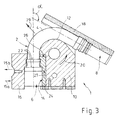
- a bow fitting 2 is exemplified in Fig. 3 shown. It consists of a tubular shaft 4 and two end portions 6, 8. In the end regions 6, 8 flange-like thickenings are present as connection or connection elements.
- the shaft 4 of the curved fitting 2 is bent or bent at a certain bending angle ⁇ .
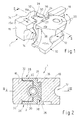
- the bending tool 1 consists of a bending head 10 with a groove or channel-like, corresponding to a desired bending contour of the shaft 4 extending shank receptacle 12 and a clamping portion 14 for the first end portion 6 of the curved armature 2. Furthermore, the bending tool 1 consists of a clamping in the 14th for clamping the first end portion 6 of the curved armature 2 in the direction of arrow 15a against the bending head 10 pressable clamping piece 16 and a jib 18 for supporting conditioning of the second end portion 8 of the curved armature 2 during the bending process (see Fig. 3 ). The clamping piece 16 can be moved away from the bending head 10 after the bending operation in the direction of arrow 15b.
- the bending head 10 in the clamping area 14 has a clamping carriage 24 displaceable relative to the curved curved armature 2 in order to provide a clearance clearance.
- This clamping slide 24 is displaceable in the axial direction of the first end portion 6 of the curved armature 2 and in the direction of the adjacent shaft 4, preferably against spring force from a starting position for the bending operation in the direction of arrow 27 in a release position for removing the curved curved armature 2.
- To generate the return -Federkraft is between the bending head 10 and the clamping slide 24 at least one compression spring 26, but preferably two compression springs 26, arranged (see Fig. 2 and 3 ).
- a locking device 28 is provided such that the clamping slide 24 is blocked in the tensioned state of the clamping piece 16 against displacement and only after release of the clamping piece 16 is released to move.
- the locking device 28 positive locking elements (30, 32) between the clamping piece 16 and the clamping slide 24 such that the positive-locking elements in the tensioned state of the clamping piece 16 (FIG. Fig. 2 ) in engagement and in the released state are at least as far out of engagement that the clamping slide 24 to create the release clearance in the direction of arrow 27 is displaceable.
- the described form-locking elements consist in the illustrated embodiment of at least one approach 30 and a corresponding, the approach 30 receiving recess 32.
- the Approach 30 aligned according to the direction of a clamping movement axis 34 of the clamping piece 16 (see Fig. 1 ).
- the clamping slide 24 has the at least one projection 30 and the clamping piece 16 has the corresponding recess 32.
- the shank receptacle 12 in the clamping area 14 enclosing clamping slide 24 with two lugs 30 in corresponding recesses 32 of the clamping piece 16 a; please refer Fig. 2 ,
- the engagement contour of the interlocking elements 30, 32 is designed so that when dissolved clamping piece 16 sufficient movement play for moving the clamping carriage 24 is formed. According to Fig. 1 This can be realized by sloping edges 36 for expanding the recesses 32. In the tensioned state of the clamping piece 16, a positive locking of the clamping carriage 24 is ensured against displacement in the direction of arrow 27 by the interlocking elements 30, 32.
- the clamping slide 24 is connected via a sliding guide 38 with the bending head 10.
- the sliding guide 38 is designed in the form of a T-connection. Also, a dovetail joint or the like is suitable.
Landscapes
- Engineering & Computer Science (AREA)
- Mechanical Engineering (AREA)
- Bending Of Plates, Rods, And Pipes (AREA)
- Clamps And Clips (AREA)
- Gripping Jigs, Holding Jigs, And Positioning Jigs (AREA)
- Mounting, Exchange, And Manufacturing Of Dies (AREA)
Description
- Die vorliegende Erfindung betrifft ein Biegewerkzeug zum Biegen von Hydraulik-Bogenarmaturen nach dem Oberbegriff des Anspruchs 1. Ein solches Biegewerkzeug ist aus dem
EP-A-0319400 bekannt. - Zur Verbindung von relativ zueinander beweglichen Druckaggregaten, beispielsweise bei Baumaschinen, wie Bagger-Armen, werden zur Versorgung von beweglichen Antriebszylindern mit Druckmittel flexible, druckfeste Hydraulikleitungen benötigt. Diese Leitungen sind mit zwei endseitigen Anschlussarmaturen konfektioniert. In vielen Fällen ist mindestens eine der Anschlussarmaturen als eine mit einem bestimmten Biegungswinkel gekrümmte Bogenarmatur ausgebildet, um im angeschlossenen Zustand einen möglichst knickfreien und allenfalls mit möglichst großem Radius gekrümmten Verlauf der Leitung zu erreichen. Jede Bogenarmatur besteht aus einem gebogenen rohrförmigen Schaft und zwei gegenüberliegenden, verdickten Endbereichen mit flanschartigen Verbindungselementen.
- Solche Bogenarmaturen werden mit Biegewerkzeugen der genannten, gattungsgemäßen Art gebogen. Bisher war dies mit bekannten Biegewerkzeugen ohne eine Demontage des Werkzeuges (z. B. ohne Auseinanderschrauben) nur bis zu einem maximalen Biegungswinkel von bis zu 90° möglich.
- Die
EP 0 737 526 A1 beschreibt mehrere verschiedene Ausführungen einer Biegevorrichtung für Rohre, allerdings speziell nur für längere, durchgehende Rohre ohne endseitige, durch z. B. flanschartige Verbindungselemente verdickte Endbereiche. Solche einfachen Rohre können - je nach Verlauf einer Teilungsebene zwischen Biegekopf und Spannstück - um bis zu 180° oder sogar mehr umgebogen werden. Die bekannte Biegevorrichtung ist allerdings für Bogenarmaturen der hier erläuterten Art nicht geeignet. Im Rohr-Einspannbereich weist die bekannte Vorrichtung mindestens einen zusätzlichen Spannkeil auf, der in Rohr-Längsrichtung in eine korrespondierende Ausnehmung einschiebbar ist, um die Einspannung des Rohres zu verbessern. - Der vorliegenden Erfindung liegt die Aufgabe zugrunde, ein Biegewerkzeug der im Oberbegriff des Anspruchs 1 genannten Art zu schaffen, welches mit konstruktiv einfachen Mitteln und ohne Demontage auch zum Biegen von Bogenarmaturen mit einem Biegungswinkel über 90° geeignet ist.
- Erfindungsgemäß wird dies durch die Merkmale des Anspruchs 1 erreicht. Vorteilhafte Ausgestaltungen der Erfindung sind in den abhängigen Ansprüchen enthalten.
- Demnach weist erfindungsgemäß der Biegekopf im Einspannbereich einen zur Schaffung eines Lösespiels relativ zu dem verdickten Endbereich der gebogenen Bogenarmatur in Achsrichtung des ersten Endbereiches verschiebbaren Spannschlitten auf. Durch diese sehr einfache aber wirkungsvolle Maßnahme wird erreicht, dass die Bogenarmatur mit ihrem durch das flanschartige Anschlusselement verdickten Endbereich durch eine Lösebewegung des Spannschlittens so freigegeben wird, dass sie nachfolgend mit dem gebogenen Schaft aus der Rohr-Aufnahme entnommen werden kann.
- Anhand eines bevorzugten, in der Zeichnung veranschaulichten Ausführungsbeispiels soll die Erfindung genauer erläutert werden. Dabei zeigen:
- Fig. 1
- eine Perspektivansicht eines erfindungsgemäßen Biegewerkzeugs,
- Fig. 2
- einen Schnitt in der Ebene II - II gemäß
Fig. 1 und - Fig. 3
- einen Schnitt in der Ebene III - III gemäß
Fig. 2 während bzw. nach einem Biegevorgang mit einer gebogenen Bogenarmatur zur Erläuterung des Vorgangs zur Freigabe. - In den verschiedenen Figuren der Zeichnung sind gleiche Teile stets mit den gleichen Bezugszeichen versehen.
- Ein erfindungsgemäßes Biegewerkzeug 1 ist zum Biegen von Hydraulik-Bogenarmaturen konzipiert. Eine solche Bogenarmatur 2 ist beispielhaft in
Fig. 3 dargestellt. Sie besteht aus einem rohrförmigen Schaft 4 und zwei Endbereichen 6, 8. In den Endbereichen 6, 8 sind flanschartige Verdickungen als Verbindungs- bzw. Anschlusselemente vorhanden. Der Schaft 4 der Bogenarmatur 2 ist mit einem bestimmten Biegewinkel α gebogen bzw. zu biegen. - Gemäß
Fig. 1 bis 3 besteht das Biegewerkzeug 1 aus einem Biegekopf 10 mit einer nut- oder rinnenartigen, entsprechend einer gewünschten Biegekontur des Schaftes 4 verlaufenden Schaft-Aufnahme 12 und einem Einspannbereich 14 für den ersten Endbereich 6 der Bogenarmatur 2. Weiterhin besteht das Biegewerkzeug 1 aus einem im Einspannbereich 14 zum Einspannen des ersten Endbereichs 6 der Bogenarmatur 2 in Pfeilrichtung 15a gegen den Biegekopf 10 pressbaren Spannstück 16 sowie einem Anlegestück 18 zur abstützenden Anlage des zweiten Endbereichs 8 der Bogenarmatur 2 während des Biegevorgangs (siehe hierzuFig. 3 ). Das Spannstück 16 ist nach dem Biegevorgang in Pfeilrichtung 15b vom Biegekopf 10 wegbewegbar. - Zum Biegen des Schaftes 4 sind der Biegekopf 10 und das Anlagestück 18 relativ zueinander entsprechend der in
Fig. 1 und3 eingezeichneten Pfeile 20 verschwenkbar. Wie sich dabei ausFig. 3 ergibt, war es bisher bei einem Biegewinkel α > 90° nicht ohne Weiteres möglich, die Armatur 2 aus dem Werkzeug 1 zu entnehmen, weil der erste Endbereich 6 aufgrund von radialen Kanten 22 nicht aus der Kontur im Einspannbereich 14 des Biegekopfes 10 gelöst werden konnte. Daher waren - ohne Demontage des Werkzeugs - nur Biegewinkel α ≤ 90° möglich. - Erfindungsgemäß weist nun der Biegekopf 10 im Einspannbereich 14 einen zur Schaffung eines Lösespiels relativ zu der gebogenen Bogenarmatur 2 verschiebbaren Spannschlitten 24 auf. Dieser Spannschlitten 24 ist in Achsrichtung des ersten Endbereichs 6 der Bogenarmatur 2 und in Richtung des angrenzenden Schaftes 4 verschiebbar, und zwar bevorzugt gegen Federkraft aus einer Ausgangsstellung für den Biegevorgang in Pfeilrichtung 27 in eine Lösestellung zum Entnehmen der gebogenen Bogenarmatur 2. Zur Erzeugung der Rückstell-Federkraft ist zwischen dem Biegekopf 10 und dem Spannschlitten 24 mindestens eine Druckfeder 26, bevorzugt aber zwei Druckfedern 26, angeordnet (siehe hierzu
Fig. 2 und3 ). - Durch Verschieben des Spannschlittens 24 in die Lösestellung entsteht zur Bogenarmatur 2 ein Lösespiel, so dass deren radialen Kanten 22 aus der inneren Kontur im Einspannbereich 14 freikommen und dann die Bogenarmatur 2 in Pfeilrichtung 29 aus der Schaft-Aufnahme 12 entnommen werden kann (
Fig. 3 ). Dadurch sind maximale Biegewinkel α im Bereich von 150° bis 160° möglich. - In weiterer vorteilhafter Ausgestaltung der Erfindung ist eine Sperreinrichtung 28 derart vorgesehen, dass der Spannschlitten 24 im gespannten Zustand des Spannstückes 16 gegen Verschieben blockiert ist und erst nach Lösen des Spannstückes 16 zum Verschieben freigegeben wird. Wie sich aus
Fig. 1 und 2 ergibt, weist die Sperreinrichtung 28 Formschlusselemente (30, 32) zwischen dem Spannstück 16 und dem Spannschlitten 24 derart auf, dass die Formschlusselemente im gespannten Zustand des Spannstückes 16 (Fig. 2 ) in Eingriff und im gelösten Zustand zumindest soweit außer Eingriff sind, dass der Spannschlitten 24 zur Schaffung des Lösespiels in Pfeilrichtung 27 verschiebbar ist. Die beschriebenen Formschlusselemente bestehen im dargestellten Ausführungsbeispiel aus mindestens einem Ansatz 30 und einer korrespondierenden, den Ansatz 30 aufnehmenden Ausnehmung 32. Dabei ist der Ansatz 30 entsprechend der Richtung einer Spannbewegungsachse 34 des Spannstückes 16 ausgerichtet (sieheFig. 1 ). Bei der bevorzugten, dargestellten Ausführung weist der Spannschlitten 24 den mindestens einen Ansatz 30 und das Spannstück 16 die korrespondierende Ausnehmung 32 auf. Vorzugsweise greift dabei der im Querschnitt C-förmige, die Schaft-Aufnahme 12 im Einspannbereich 14 umschließende Spannschlitten 24 mit zwei Ansätzen 30 in korrespondierende Ausnehmungen 32 des Spannstückes 16 ein; sieheFig. 2 . - Natürlich ist auch eine umgekehrte Ausführung möglich, wobei vorzugsweise das im Querschnitt etwa C-förmige, den Einspannbereich umschließende Spannstück 16 mit zwei Ansätzen in korrespondierende Ausnehmungen des Spannschlittens eingreift.
- In allen Fällen ist die Eingriff-Kontur der Formschlusselemente 30, 32 so ausgelegt, dass bei gelöstem Spannstück 16 ein ausreichendes Bewegungsspiel zum Verschieben des Spannschlittens 24 entsteht. Gemäß
Fig. 1 kann dies durch schräge Kanten 36 zur Erweiterung der Ausnehmungen 32 realisiert werden. Im gespannten Zustand des Spannstückes 16 wird durch die Formschlusselemente 30, 32 eine formschlüssige Blockierung des Spannschlittens 24 gegen Verschiebung in Pfeilrichtung 27 gewährleistet. - Wie sich schließlich noch aus
Fig. 1 und 2 ergibt, ist der Spannschlitten 24 über eine Schiebeführung 38 mit dem Biegekopf 10 verbunden. Bei der dargestellten Ausführung ist die Schiebeführung 38 in Form einer T-Verbindung ausgeführt. Ebenfalls ist auch eine Schwalbenschwanzverbindung oder dergleichen geeignet.
Claims (8)
- Biegewerkzeug (1) zum Biegen eines rohrförmigen Schaftes (4) einer Hydraulik-Bogenarmatur (2), mit einem Biegekopf (10) mit einer rinnenartigen, entsprechend einer gewünschten Biegekontur des Schaftes (4) verlaufenden Schaft-Aufnahme (12) und einem Einspannbereich (14) für einen ersten, gegenüber dem Schaft (4) verdickten Endbereich (6) der zu biegenden Bogenarmatur (2) und mit einem im Einspannbereich (14) zum Einspannen des ersten Endbereichs (6) der Bogenarmatur (2) gegen den Biegekopf (10) pressbaren Spannstück (16),
dadurch gekennzeichnet, dass der Biegekopf (10) im Einspannbereich (14) einen zur Schaffung eines Lösespiels relativ zu dem Endbereich (6) der gebogenen Bogenarmatur (2) in Achsrichtung des ersten Endbereichs (6) verschiebbaren Spannschlitten (24) aufweist. - Biegewerkzeug nach Anspruch 1,
dadurch gekennzeichnet, dass derSpannschlitten(24)aus einer Ausgangsstellung gegen Federkraft in eine Lösestellung verschiebbar ist. - Biegewerkzeug nach Anspruch 1 oder 2,
gekennzeichnet durch eine Sperreinrichtung (28) derart, dass der Spannschlitten (24) im gespannten Zustand des Spannstückes (16) gegen Verschieben blockiert ist und erst nach Lösen des Spannstückes (16) zum Verschieben freigegeben wird. - Biegewerkzeug nach Anspruch 3,
dadurch gekennzeichnet, dass die Sperreinrichtung (28) Formschlusselemente (30, 32) zwischen dem Spannstück (16) und dem Spannschlitten (24) derart aufweist, dass die Formschlusselemente (30, 32) im gespannten Zustand des Spannstückes (16) in Eingriff und im gelösten Zustand zumindest so weit außer Eingriff sind, dass der Spannschlitten (24) zur Schaffung des Lösespiels verschiebbar ist. - Biegewerkzeug nach Anspruch 4,
dadurch gekennzeichnet, dass die Formschlusselemente aus mindestens einem entsprechend der Richtung einer Spannungsbewegungsachse (34) des Spannstückes (16) ausgerichteten Ansatz (30) und einer korrespondierenden, den Ansatz (30) aufnehmenden Ausnehmung (32) bestehen. - Biegewerkzeug nach Anspruch 5,
dadurch gekennzeichnet, dass der im Querschnitt etwa C-förmige Spannschlitten (24) mit zwei Ansätzen (30) in korrespondierende Ausnehmungen (32) des Spannstückes (16) eingreift. - Biegewerkzeug nach Anspruch 5,
dadurch gekennzeichnet, dass das im Querschnitt etwa C-förmige Spannstück (16) mit zwei Ansätzen (30) in korrespondierende Ausnehmungen (32) des Spannschlittens (24) eingreift. - Biegewerkzeug nach einem der Ansprüche 1 bis 7,
dadurch gekennzeichnet, dass der Spannschlitten (24) über eine Schiebeführung (38), z. B. in Form einer T-Verbindung oder einer Schwalbenschwanzverbindung, mit dem Biegekopf (10) verbunden ist.
Priority Applications (1)
| Application Number | Priority Date | Filing Date | Title |
|---|---|---|---|
| PL06119537T PL1767285T3 (pl) | 2005-09-21 | 2006-08-25 | Narzędzie wyginające do hydraulicznej armatury kolankowej |
Applications Claiming Priority (1)
| Application Number | Priority Date | Filing Date | Title |
|---|---|---|---|
| DE202005014938U DE202005014938U1 (de) | 2005-09-21 | 2005-09-21 | Biegewerkzeug für Hydraulik-Bogenarmaturen |
Publications (3)
| Publication Number | Publication Date |
|---|---|
| EP1767285A1 EP1767285A1 (de) | 2007-03-28 |
| EP1767285A8 EP1767285A8 (de) | 2007-08-08 |
| EP1767285B1 true EP1767285B1 (de) | 2008-03-19 |
Family
ID=35512227
Family Applications (1)
| Application Number | Title | Priority Date | Filing Date |
|---|---|---|---|
| EP06119537A Not-in-force EP1767285B1 (de) | 2005-09-21 | 2006-08-25 | Biegewerkzeug für Hydraulik-Bogenarmaturen |
Country Status (4)
| Country | Link |
|---|---|
| EP (1) | EP1767285B1 (de) |
| AT (1) | ATE389474T1 (de) |
| DE (2) | DE202005014938U1 (de) |
| PL (1) | PL1767285T3 (de) |
Families Citing this family (2)
| Publication number | Priority date | Publication date | Assignee | Title |
|---|---|---|---|---|
| CN111545606B (zh) * | 2020-06-19 | 2021-12-03 | 项军炎 | 一种钢管折弯加工工艺 |
| CN111545607B (zh) * | 2020-06-19 | 2021-12-14 | 济南科德智能科技有限公司 | 一种钢管折弯加工设备 |
Citations (1)
| Publication number | Priority date | Publication date | Assignee | Title |
|---|---|---|---|---|
| EP0319400A1 (de) * | 1987-12-02 | 1989-06-07 | Societe Nationale D'etude Et De Construction De Moteurs D'aviation, "S.N.E.C.M.A." | Rohrleitungsbiegegerät und Verfahren zum Herstellen einer Rohrleitung mit geschweisstem Ansatzstück |
Family Cites Families (2)
| Publication number | Priority date | Publication date | Assignee | Title |
|---|---|---|---|---|
| US5187963A (en) * | 1992-06-12 | 1993-02-23 | Moiron | Tube bending die |
| NL1000150C1 (nl) * | 1995-04-13 | 1996-10-15 | Busschers Metaalbedrijf Bv | Inrichting voor het buigen van pijpen. |
-
2005
- 2005-09-21 DE DE202005014938U patent/DE202005014938U1/de not_active Expired - Lifetime
-
2006
- 2006-08-25 PL PL06119537T patent/PL1767285T3/pl unknown
- 2006-08-25 AT AT06119537T patent/ATE389474T1/de active
- 2006-08-25 DE DE502006000490T patent/DE502006000490D1/de active Active
- 2006-08-25 EP EP06119537A patent/EP1767285B1/de not_active Not-in-force
Patent Citations (1)
| Publication number | Priority date | Publication date | Assignee | Title |
|---|---|---|---|---|
| EP0319400A1 (de) * | 1987-12-02 | 1989-06-07 | Societe Nationale D'etude Et De Construction De Moteurs D'aviation, "S.N.E.C.M.A." | Rohrleitungsbiegegerät und Verfahren zum Herstellen einer Rohrleitung mit geschweisstem Ansatzstück |
Also Published As
| Publication number | Publication date |
|---|---|
| PL1767285T3 (pl) | 2008-08-29 |
| DE502006000490D1 (de) | 2008-04-30 |
| ATE389474T1 (de) | 2008-04-15 |
| EP1767285A1 (de) | 2007-03-28 |
| DE202005014938U1 (de) | 2005-12-22 |
| EP1767285A8 (de) | 2007-08-08 |
Similar Documents
| Publication | Publication Date | Title |
|---|---|---|
| EP2163358B1 (de) | Zusatzhandgriff für eine Handwerkzeugmaschine | |
| EP2961899B1 (de) | Betätigungshandhabe | |
| EP1600679A1 (de) | Verbindungsanordnung aus Kunststoff zum Festlegen eines Schlauches | |
| EP0452791A1 (de) | Presswerkzeug | |
| DE3423283A1 (de) | Klemmwerkzeug, insbesondere zum verbinden von rohren und anderen profilen | |
| EP2150743B1 (de) | Klemmfitting fuer ein rohr | |
| DE102005001548A1 (de) | Vorrichtung zum Betätigen eines Verriegelungsmechanismus | |
| EP1767285B1 (de) | Biegewerkzeug für Hydraulik-Bogenarmaturen | |
| DE10223894B4 (de) | Plattenklemmvorrichtung | |
| EP1649948B1 (de) | Presswerkzeug | |
| EP3016782A1 (de) | Presswerkzeug zum verbinden von werkstücken mittels umformen | |
| EP1412117B1 (de) | Distanzelement für eine spannzange und spannzange | |
| DE2835405A1 (de) | Handhebelrohrbieger | |
| DE9315482U1 (de) | Zangenartiges Werkzeug zum formschlüssigen Verbinden von Blechteilen | |
| DE20118444U1 (de) | Faltenglätter | |
| WO2021156053A1 (de) | Schraubzwinge | |
| DE9410500U1 (de) | Fluidisch betätigbares. leistenartiges Klemmwerkzeug | |
| DE2438990C2 (de) | Vorrichtung zum Fertigbiegen (Schliessen) vorgebogener Kettenglieder | |
| EP0717204A1 (de) | Sicherheitsbolzen, der in Durchgangslöcher von Bauteilen bis zu einem Anschlag einschiebbar ist | |
| AT500296B1 (de) | Einrichtung zum verriegeln von endlagen von beweglichen weichenteilen, insbesondere weichenverschluss | |
| EP2218548B1 (de) | Gelenkverbindung zum Umwandeln einer Linearbewegung in eine Schwenkbewegung und Spannvorrichtung mit einer solchen Gelenkverbindung | |
| DE102004034638B4 (de) | Biegevorrichtung für Rohre | |
| DE102006011487A1 (de) | Spanner mit Knarrenverriegelung | |
| DE4422735C1 (de) | Fluidisch betätigbares, leistenartiges Klemmwerkzeug | |
| DE20304017U1 (de) | Preßwerkzeug zur Herstellung von Rohrverbindungen |
Legal Events
| Date | Code | Title | Description |
|---|---|---|---|
| PUAI | Public reference made under article 153(3) epc to a published international application that has entered the european phase |
Free format text: ORIGINAL CODE: 0009012 |
|
| AK | Designated contracting states |
Kind code of ref document: A1 Designated state(s): AT BE BG CH CY CZ DE DK EE ES FI FR GB GR HU IE IS IT LI LT LU LV MC NL PL PT RO SE SI SK TR |
|
| AX | Request for extension of the european patent |
Extension state: AL BA HR MK YU |
|
| 17P | Request for examination filed |
Effective date: 20070604 |
|
| RAP1 | Party data changed (applicant data changed or rights of an application transferred) |
Owner name: DIPL.-ING. H. SCHULZ HDS HYDRAULIK GMBH & CO. KG |
|
| GRAP | Despatch of communication of intention to grant a patent |
Free format text: ORIGINAL CODE: EPIDOSNIGR1 |
|
| AKX | Designation fees paid |
Designated state(s): AT BE BG CH CY CZ DE DK EE ES FI FR GB GR HU IE IS IT LI LT LU LV MC NL PL PT RO SE SI SK TR |
|
| GRAS | Grant fee paid |
Free format text: ORIGINAL CODE: EPIDOSNIGR3 |
|
| GRAA | (expected) grant |
Free format text: ORIGINAL CODE: 0009210 |
|
| AK | Designated contracting states |
Kind code of ref document: B1 Designated state(s): AT BE BG CH CY CZ DE DK EE ES FI FR GB GR HU IE IS IT LI LT LU LV MC NL PL PT RO SE SI SK TR |
|
| REG | Reference to a national code |
Ref country code: GB Ref legal event code: FG4D Free format text: NOT ENGLISH |
|
| REG | Reference to a national code |
Ref country code: CH Ref legal event code: NV Representative=s name: BRAUNPAT BRAUN EDER AG Ref country code: CH Ref legal event code: EP |
|
| REF | Corresponds to: |
Ref document number: 502006000490 Country of ref document: DE Date of ref document: 20080430 Kind code of ref document: P |
|
| REG | Reference to a national code |
Ref country code: IE Ref legal event code: FG4D Free format text: LANGUAGE OF EP DOCUMENT: GERMAN |
|
| PG25 | Lapsed in a contracting state [announced via postgrant information from national office to epo] |
Ref country code: LT Free format text: LAPSE BECAUSE OF FAILURE TO SUBMIT A TRANSLATION OF THE DESCRIPTION OR TO PAY THE FEE WITHIN THE PRESCRIBED TIME-LIMIT Effective date: 20080319 Ref country code: FI Free format text: LAPSE BECAUSE OF FAILURE TO SUBMIT A TRANSLATION OF THE DESCRIPTION OR TO PAY THE FEE WITHIN THE PRESCRIBED TIME-LIMIT Effective date: 20080319 |
|
| REG | Reference to a national code |
Ref country code: PL Ref legal event code: T3 |
|
| NLV1 | Nl: lapsed or annulled due to failure to fulfill the requirements of art. 29p and 29m of the patents act | ||
| ET | Fr: translation filed | ||
| PG25 | Lapsed in a contracting state [announced via postgrant information from national office to epo] |
Ref country code: SI Free format text: LAPSE BECAUSE OF FAILURE TO SUBMIT A TRANSLATION OF THE DESCRIPTION OR TO PAY THE FEE WITHIN THE PRESCRIBED TIME-LIMIT Effective date: 20080319 Ref country code: LV Free format text: LAPSE BECAUSE OF FAILURE TO SUBMIT A TRANSLATION OF THE DESCRIPTION OR TO PAY THE FEE WITHIN THE PRESCRIBED TIME-LIMIT Effective date: 20080319 |
|
| REG | Reference to a national code |
Ref country code: IE Ref legal event code: FD4D |
|
| PG25 | Lapsed in a contracting state [announced via postgrant information from national office to epo] |
Ref country code: SK Free format text: LAPSE BECAUSE OF FAILURE TO SUBMIT A TRANSLATION OF THE DESCRIPTION OR TO PAY THE FEE WITHIN THE PRESCRIBED TIME-LIMIT Effective date: 20080319 Ref country code: ES Free format text: LAPSE BECAUSE OF FAILURE TO SUBMIT A TRANSLATION OF THE DESCRIPTION OR TO PAY THE FEE WITHIN THE PRESCRIBED TIME-LIMIT Effective date: 20080630 Ref country code: PT Free format text: LAPSE BECAUSE OF FAILURE TO SUBMIT A TRANSLATION OF THE DESCRIPTION OR TO PAY THE FEE WITHIN THE PRESCRIBED TIME-LIMIT Effective date: 20080827 Ref country code: CZ Free format text: LAPSE BECAUSE OF FAILURE TO SUBMIT A TRANSLATION OF THE DESCRIPTION OR TO PAY THE FEE WITHIN THE PRESCRIBED TIME-LIMIT Effective date: 20080319 Ref country code: SE Free format text: LAPSE BECAUSE OF FAILURE TO SUBMIT A TRANSLATION OF THE DESCRIPTION OR TO PAY THE FEE WITHIN THE PRESCRIBED TIME-LIMIT Effective date: 20080619 |
|
| PG25 | Lapsed in a contracting state [announced via postgrant information from national office to epo] |
Ref country code: RO Free format text: LAPSE BECAUSE OF FAILURE TO SUBMIT A TRANSLATION OF THE DESCRIPTION OR TO PAY THE FEE WITHIN THE PRESCRIBED TIME-LIMIT Effective date: 20080319 Ref country code: NL Free format text: LAPSE BECAUSE OF FAILURE TO SUBMIT A TRANSLATION OF THE DESCRIPTION OR TO PAY THE FEE WITHIN THE PRESCRIBED TIME-LIMIT Effective date: 20080319 |
|
| PG25 | Lapsed in a contracting state [announced via postgrant information from national office to epo] |
Ref country code: IS Free format text: LAPSE BECAUSE OF FAILURE TO SUBMIT A TRANSLATION OF THE DESCRIPTION OR TO PAY THE FEE WITHIN THE PRESCRIBED TIME-LIMIT Effective date: 20080719 |
|
| PLBE | No opposition filed within time limit |
Free format text: ORIGINAL CODE: 0009261 |
|
| STAA | Information on the status of an ep patent application or granted ep patent |
Free format text: STATUS: NO OPPOSITION FILED WITHIN TIME LIMIT |
|
| PG25 | Lapsed in a contracting state [announced via postgrant information from national office to epo] |
Ref country code: DK Free format text: LAPSE BECAUSE OF FAILURE TO SUBMIT A TRANSLATION OF THE DESCRIPTION OR TO PAY THE FEE WITHIN THE PRESCRIBED TIME-LIMIT Effective date: 20080319 Ref country code: IE Free format text: LAPSE BECAUSE OF FAILURE TO SUBMIT A TRANSLATION OF THE DESCRIPTION OR TO PAY THE FEE WITHIN THE PRESCRIBED TIME-LIMIT Effective date: 20080319 |
|
| 26N | No opposition filed |
Effective date: 20081222 |
|
| PG25 | Lapsed in a contracting state [announced via postgrant information from national office to epo] |
Ref country code: MC Free format text: LAPSE BECAUSE OF NON-PAYMENT OF DUE FEES Effective date: 20080831 |
|
| PG25 | Lapsed in a contracting state [announced via postgrant information from national office to epo] |
Ref country code: EE Free format text: LAPSE BECAUSE OF FAILURE TO SUBMIT A TRANSLATION OF THE DESCRIPTION OR TO PAY THE FEE WITHIN THE PRESCRIBED TIME-LIMIT Effective date: 20080319 Ref country code: BG Free format text: LAPSE BECAUSE OF FAILURE TO SUBMIT A TRANSLATION OF THE DESCRIPTION OR TO PAY THE FEE WITHIN THE PRESCRIBED TIME-LIMIT Effective date: 20080619 |
|
| PG25 | Lapsed in a contracting state [announced via postgrant information from national office to epo] |
Ref country code: CY Free format text: LAPSE BECAUSE OF FAILURE TO SUBMIT A TRANSLATION OF THE DESCRIPTION OR TO PAY THE FEE WITHIN THE PRESCRIBED TIME-LIMIT Effective date: 20080319 |
|
| PG25 | Lapsed in a contracting state [announced via postgrant information from national office to epo] |
Ref country code: LU Free format text: LAPSE BECAUSE OF NON-PAYMENT OF DUE FEES Effective date: 20080825 Ref country code: HU Free format text: LAPSE BECAUSE OF FAILURE TO SUBMIT A TRANSLATION OF THE DESCRIPTION OR TO PAY THE FEE WITHIN THE PRESCRIBED TIME-LIMIT Effective date: 20080920 |
|
| PG25 | Lapsed in a contracting state [announced via postgrant information from national office to epo] |
Ref country code: TR Free format text: LAPSE BECAUSE OF FAILURE TO SUBMIT A TRANSLATION OF THE DESCRIPTION OR TO PAY THE FEE WITHIN THE PRESCRIBED TIME-LIMIT Effective date: 20080319 |
|
| PG25 | Lapsed in a contracting state [announced via postgrant information from national office to epo] |
Ref country code: GR Free format text: LAPSE BECAUSE OF FAILURE TO SUBMIT A TRANSLATION OF THE DESCRIPTION OR TO PAY THE FEE WITHIN THE PRESCRIBED TIME-LIMIT Effective date: 20080620 |
|
| PGFP | Annual fee paid to national office [announced via postgrant information from national office to epo] |
Ref country code: CH Payment date: 20110812 Year of fee payment: 6 |
|
| PGFP | Annual fee paid to national office [announced via postgrant information from national office to epo] |
Ref country code: BE Payment date: 20120820 Year of fee payment: 7 |
|
| PGFP | Annual fee paid to national office [announced via postgrant information from national office to epo] |
Ref country code: AT Payment date: 20120810 Year of fee payment: 7 |
|
| BERE | Be: lapsed |
Owner name: DIPL.-ING. H. SCHULZ HDS HYDRAULIK G.M.B.H. & CO. Effective date: 20130831 |
|
| REG | Reference to a national code |
Ref country code: CH Ref legal event code: PL |
|
| REG | Reference to a national code |
Ref country code: AT Ref legal event code: MM01 Ref document number: 389474 Country of ref document: AT Kind code of ref document: T Effective date: 20130825 |
|
| PG25 | Lapsed in a contracting state [announced via postgrant information from national office to epo] |
Ref country code: LI Free format text: LAPSE BECAUSE OF NON-PAYMENT OF DUE FEES Effective date: 20130831 Ref country code: CH Free format text: LAPSE BECAUSE OF NON-PAYMENT OF DUE FEES Effective date: 20130831 |
|
| PG25 | Lapsed in a contracting state [announced via postgrant information from national office to epo] |
Ref country code: AT Free format text: LAPSE BECAUSE OF NON-PAYMENT OF DUE FEES Effective date: 20130825 Ref country code: BE Free format text: LAPSE BECAUSE OF NON-PAYMENT OF DUE FEES Effective date: 20130831 |
|
| REG | Reference to a national code |
Ref country code: FR Ref legal event code: PLFP Year of fee payment: 11 |
|
| PGFP | Annual fee paid to national office [announced via postgrant information from national office to epo] |
Ref country code: DE Payment date: 20161031 Year of fee payment: 11 |
|
| REG | Reference to a national code |
Ref country code: FR Ref legal event code: PLFP Year of fee payment: 12 |
|
| PGFP | Annual fee paid to national office [announced via postgrant information from national office to epo] |
Ref country code: IT Payment date: 20170824 Year of fee payment: 12 Ref country code: FR Payment date: 20170829 Year of fee payment: 12 Ref country code: GB Payment date: 20170823 Year of fee payment: 12 |
|
| PGFP | Annual fee paid to national office [announced via postgrant information from national office to epo] |
Ref country code: PL Payment date: 20170821 Year of fee payment: 12 |
|
| REG | Reference to a national code |
Ref country code: DE Ref legal event code: R119 Ref document number: 502006000490 Country of ref document: DE |
|
| PG25 | Lapsed in a contracting state [announced via postgrant information from national office to epo] |
Ref country code: DE Free format text: LAPSE BECAUSE OF NON-PAYMENT OF DUE FEES Effective date: 20180301 |
|
| GBPC | Gb: european patent ceased through non-payment of renewal fee |
Effective date: 20180825 |
|
| PG25 | Lapsed in a contracting state [announced via postgrant information from national office to epo] |
Ref country code: IT Free format text: LAPSE BECAUSE OF NON-PAYMENT OF DUE FEES Effective date: 20180825 |
|
| PG25 | Lapsed in a contracting state [announced via postgrant information from national office to epo] |
Ref country code: FR Free format text: LAPSE BECAUSE OF NON-PAYMENT OF DUE FEES Effective date: 20180831 |
|
| PG25 | Lapsed in a contracting state [announced via postgrant information from national office to epo] |
Ref country code: GB Free format text: LAPSE BECAUSE OF NON-PAYMENT OF DUE FEES Effective date: 20180825 |
|
| PG25 | Lapsed in a contracting state [announced via postgrant information from national office to epo] |
Ref country code: PL Free format text: LAPSE BECAUSE OF NON-PAYMENT OF DUE FEES Effective date: 20180825 |