EP0158773B1 - Radstellungs-Messvorrichtung - Google Patents
Radstellungs-Messvorrichtung Download PDFInfo
- Publication number
- EP0158773B1 EP0158773B1 EP85101020A EP85101020A EP0158773B1 EP 0158773 B1 EP0158773 B1 EP 0158773B1 EP 85101020 A EP85101020 A EP 85101020A EP 85101020 A EP85101020 A EP 85101020A EP 0158773 B1 EP0158773 B1 EP 0158773B1
- Authority
- EP
- European Patent Office
- Prior art keywords
- measuring
- measuring device
- angle
- plates
- yoke
- Prior art date
- Legal status (The legal status is an assumption and is not a legal conclusion. Google has not performed a legal analysis and makes no representation as to the accuracy of the status listed.)
- Expired
Links
- 238000005259 measurement Methods 0.000 claims description 31
- 239000003302 ferromagnetic material Substances 0.000 claims 1
- 238000010276 construction Methods 0.000 description 5
- 238000012360 testing method Methods 0.000 description 3
- XEEYBQQBJWHFJM-UHFFFAOYSA-N Iron Chemical compound [Fe] XEEYBQQBJWHFJM-UHFFFAOYSA-N 0.000 description 2
- 238000013459 approach Methods 0.000 description 1
- 238000013461 design Methods 0.000 description 1
- 238000010586 diagram Methods 0.000 description 1
- 230000006870 function Effects 0.000 description 1
- 229910052742 iron Inorganic materials 0.000 description 1
- 238000002372 labelling Methods 0.000 description 1
- 238000003754 machining Methods 0.000 description 1
- 238000000034 method Methods 0.000 description 1
- 238000012545 processing Methods 0.000 description 1
Images


Classifications
-
- G—PHYSICS
- G01—MEASURING; TESTING
- G01B—MEASURING LENGTH, THICKNESS OR SIMILAR LINEAR DIMENSIONS; MEASURING ANGLES; MEASURING AREAS; MEASURING IRREGULARITIES OF SURFACES OR CONTOURS
- G01B5/00—Measuring arrangements characterised by the use of mechanical techniques
- G01B5/24—Measuring arrangements characterised by the use of mechanical techniques for measuring angles or tapers; for testing the alignment of axes
- G01B5/255—Measuring arrangements characterised by the use of mechanical techniques for measuring angles or tapers; for testing the alignment of axes for testing wheel alignment
-
- G—PHYSICS
- G01—MEASURING; TESTING
- G01B—MEASURING LENGTH, THICKNESS OR SIMILAR LINEAR DIMENSIONS; MEASURING ANGLES; MEASURING AREAS; MEASURING IRREGULARITIES OF SURFACES OR CONTOURS
- G01B7/00—Measuring arrangements characterised by the use of electric or magnetic techniques
- G01B7/30—Measuring arrangements characterised by the use of electric or magnetic techniques for measuring angles or tapers; for testing the alignment of axes
- G01B7/315—Measuring arrangements characterised by the use of electric or magnetic techniques for measuring angles or tapers; for testing the alignment of axes for testing wheel alignment
-
- Y—GENERAL TAGGING OF NEW TECHNOLOGICAL DEVELOPMENTS; GENERAL TAGGING OF CROSS-SECTIONAL TECHNOLOGIES SPANNING OVER SEVERAL SECTIONS OF THE IPC; TECHNICAL SUBJECTS COVERED BY FORMER USPC CROSS-REFERENCE ART COLLECTIONS [XRACs] AND DIGESTS
- Y10—TECHNICAL SUBJECTS COVERED BY FORMER USPC
- Y10S—TECHNICAL SUBJECTS COVERED BY FORMER USPC CROSS-REFERENCE ART COLLECTIONS [XRACs] AND DIGESTS
- Y10S33/00—Geometrical instruments
- Y10S33/01—Magnetic
Definitions
- the invention relates to a wheel position measuring device for determining the angular position of a pair of wheels of the steerable axle of a motor vehicle, wherein the wheel position measuring device can be attached to the wheels at right angles to their axis of rotation, measuring disks, a connecting bridge that the part of the measuring device assigned to one wheel and the other Connects the wheel-associated part of the measuring device, and has at least one angle measuring device which can be attached to the connecting bridge, with which the angular positions of the measuring disks can be measured with respect to the connecting bridge oriented perpendicular to the direction of travel of the motor vehicle, and wherein measuring plates are arranged on the connecting bridge in planes perpendicular to it, from each of which extends in the horizontal direction to below the assigned measuring disc when the connecting bridge is in the operating position on the motor vehicle.
- Such a measuring device is known from CH-A-424 288, in which two measuring heads with a plurality of sensing elements are provided on a connecting bridge for determining the axis inclination of the wheels. Measuring surfaces are arranged on the wheels which can be adjusted in two dimensions in order to be able to set the measuring surfaces at right angles to the wheel bearing axis. After the alignment of the connecting bridge perpendicular to the axis of symmetry of the motor vehicle and after the alignment of the measuring heads perpendicular to the wheel bearing axis, the measuring heads, which have several sensing elements, are fed to the measuring surfaces, the sensing elements then detecting the desired angles.
- the accuracy of the measurement depends on the measuring surfaces being aligned exactly perpendicular to the wheel bearing axis. In practice, this is only guaranteed if the vehicle is raised and the wheels can be turned. Both lifting and turning the wheels are associated with a great deal of effort and effort in trucks and buses.
- the invention has for its object to provide a simple and robust measuring device with which the angular position of a pair of wheels, in particular the track, can be measured accurately.
- the angle measuring device has a head pivotably mounted about the longitudinal axis of its housing and an angle encoder which measures the pivoting of the head around the longitudinal axis, and that the angle measuring device for measurement the track is approximately vertical, with the housing on the measuring plate and with the head on the measuring plate assigned to the measuring plate.
- a measuring plate is thus placed on the wheel next to the measuring disc, which is arranged on the connecting bridge, and the angle measuring devices measure the angles between the surface of the measuring disc and the surface of the associated measuring plate in the vertical direction.
- the angles can be measured using simple, robust and robust measuring devices.
- the configuration of the measuring device according to the invention according to claim 2 additionally allows the measurement of the camber, whereby according to the further advantageous configuration according to claim 3, both track and camber values can be measured simultaneously and fed to a control unit for processing.
- the configuration of the measuring device according to the invention according to claim 4 is advantageous in that a distance between the surface of the measuring disk and the surface of the measuring plate can be recorded without stressing the parts of the angle measuring device and without loss of accuracy of the measurement.
- the design of the measuring device according to the invention according to claim 5 has the advantage that a simple rotary potentiometer is used as an angle encoder, so that the pivoting of the stator head is measured directly and without the interposition of further mechanical means and thus precisely by placing the stator attached to it.
- the angle measuring devices can be placed in the simplest manner on the measuring disks and measuring plates, and, due to the diameter of the measuring disks and the width of the measuring plates, the placement of the angle meters is given extensive freedom which can has an advantageous effect when using the measuring device in different vehicle types.
- the angle measuring device contains a measuring circuit with a display device. When placing the angle measuring device in the appropriate measuring position, the measured value can be read off immediately. In this context, it is advantageous if the angle measuring device is equipped according to claim 8, since in this embodiment the angle is not only of size can be read correctly, but also according to their sign.
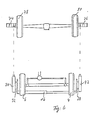
- FIG. 1 the front of a motor vehicle 2 with the front wheels 4, 6 is shown schematically.
- the main parts of the measuring device namely a measuring disk 8 on the left front wheel 4, a measuring disk 10 (FIG. 2) on the right front wheel 6, measuring plates 28, 30; 32, 34 on the left and right front wheels, a connecting bridge 16 which connects the measuring plates to one another and keeps them parallel to one another, and angle measuring devices 18, 20 on the left front wheel and angle measuring devices 22, 24 (FIG. 2) on the right front wheel .
- the measuring device is completed by a control unit (not shown) in which the measured values output by the angle measuring devices can be processed and displayed as camber and track measured values.
- the measuring disks 8, 10 are fixedly connected to the wheels 4, 6 by three-armed holding devices 26.
- the holding devices 26 must be able to participate in half a revolution of the wheels 4 without changing their position on the wheels.
- the holding devices 26 can be mechanical clamps or expediently double-acting magnets which are inserted between the wheel and the associated measuring disk. No measures are required on the holding devices 26 in order to compensate for a possible rim runout.
- the outer surfaces of the measuring disks 8, 10 are therefore, apart from the rim runout, perpendicular to the axis of rotation of the respective wheels.
- the measuring disks 8, 10 have machined, flat surfaces and can be kept thin since they are only exposed to a small amount of stress.
- the connecting bridge 16 can, for. B. consist of two telescopically movable parts, at the ends of the measuring plates 28, 30; 32, 34 are arranged perpendicular to the longitudinal direction of the connecting bridge 16 and parallel to one another. Because the connecting bridge 16 can be telescoped, the measuring plates 28, 30; 32, 34 on the level of the measuring disks 8, 10 are pushed up on the wheels.
- the connecting bridge 16 lies transversely to the direction of travel of the vehicle in front of the wheels 4, 6 to be measured.
- the measuring plates 28, 32 are aligned horizontally, while the other measuring plates 30, 34 are oriented vertically.
- the horizontal measuring plates 28.32 extend from the connecting bridge 16 at least to below the center of the assigned measuring disks and the vertical measuring plates 30, 34 extend from the connecting bridge 16 at least to the middle of the assigned measuring disks.
- the measuring plates can be brought with their flat outer surface substantially below or in front of the plane of the measuring disks 8, 10 mounted on the wheels.
- This position of the measuring plates can be fixed by a clamping device (not shown) on the connecting bridge by z. B. the telescopic parts of the connecting bridge 16 are locked together.
- the adjustability of the connecting bridge 16 also makes it possible to measure motor vehicles of different track widths.
- the connecting bridge 16 can be equipped with small wheels (not shown).
- the connecting bridge 16 can also consist of a profile rail, which protrudes beyond the vehicle width and on the two heads, which carry the horizontal measuring plates 28, 32 or all four measuring plates 25, 30, 32, 34, the vehicle width according to the vehicle width and clamped .
- the angle measuring devices 18, 20, 22, 24 serve to detect the angular position between the planes of the surfaces of the measuring plates 28, 30; 32, 34 and the planes of the surfaces of the measuring disks 8, 10.
- the angle measuring devices 18, 22 (FIGS. 1 and 2) are arranged vertically, connect the measuring disks 8, 10 to the measuring plates 28, 32 and serve to determine a toe angle, ie the Angle of a measuring disc to the associated measuring plate in a horizontal plane.
- the angle measuring devices 20, 24 are arranged horizontally, connect the measuring disks 8, 10 to the vertical measuring plates 30, 34 and serve to detect the camber, ie the angle between the measuring disk and the associated measuring plate in a vertical plane.
- the embodiment of the measuring device described above and shown in the figures thus allows both the measurement of the camber and the measurement of the track.
- the simplified embodiment of the measuring device in which only the measuring plates 28 and 32 are arranged on the connecting bridge 16, represents a functional device for measuring the track and can be used as such for measuring the wheel position if only the Track measurement is desirable, as is the case with trucks and buses, for example.
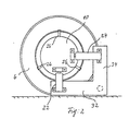
- the angle measuring device 18 has a housing 40 on which two stands 42, 44 are arranged at the opposite ends.
- the stand 42 is fastened to a head 46 which is fastened on a shaft 47 of a rotary potentiometer 48 lying in the longitudinal center axis of the housing 40. So that the stand 42 is pivotally mounted about the longitudinal axis of the housing 40.
- the rotary potentiometer 48 serves as an angle encoder, which measures the pivoting of the head 46 and thus of the stand 42 about the longitudinal axis of the housing.
- the stands 42, 44 are also pivoted about axes 50, 52 which are perpendicular to the longitudinal axis of the housing 40. A distance between the surfaces of the measuring disks and the surfaces of the measuring plates 28, 30, 32, 34 can thus be compensated for and stresses on the shaft 47 of the rotary potentiometer 48 avoided.
- the stand 44 has lateral legs 54, 56, which extend from the axis of rotation 52 mounted in the housing 40 to a base plate 58, which has a greater width than the housing 40, in order to have a wider measuring base receive.
- Two permanent magnets 60, 62 are attached below the base plate 58.
- the stand 42 is constructed in the same way as the stand 44 and also has two permanent magnets 64, 66. With the help of the permanent magnets 60, 62, 64, 66, the angle measuring device 18 can be placed on the measuring disk 8 on the one hand and the measuring plate 28 on the other hand and held thereon, if the measuring disks and measuring plates are made of iron or the like.
- angular measuring devices can be put on and taken off quickly, a certain freedom in the choice of the place where the angular measuring devices are to be attached, and simple machining of the surfaces, the measuring disks and plates.
- other guiding and clamping devices such as slide rails or prisms, can also be used to fasten the angle measuring devices to the measuring disks and measuring plates.
- the angle measuring devices 18, 20, 22, 24 are used to measure track and camber from the relative angular position of the planes of the measuring disks 8, 10 to the measuring plates.
- the angle measuring devices 18, 22, used vertically serve to measure the track, i.e. they measure the angular position of the measuring disks 8, 10 relative to the horizontal measuring plates 28, 32.
- the angle sensors 20, 24 serve to record the real camber value, i.e. they measure the angular position of the measuring disks 8, 10 relative to the vertical measuring plates 30, 34.
- the creation of a horizontal measuring station is not a condition, i.e. the measurement is independent of location.
- the individual track values in the middle position of the steering are precisely detected by the rotary potentiometers in the angle measuring devices when the connecting bridge 16 is at right angles to the axis of symmetry of the motor vehicle to be measured, since the measuring plates 28, 32 are then parallel to the axis of symmetry.
- the potentiometers in the corresponding angle measuring devices show an output signal "0". If the measuring disks and the measuring plates are at an angle to each other, the shaft of the potentiometer in question is rotated accordingly when the angle measuring devices are attached, so that its output signal indicates the measured angle.
- the signals emitted by the potentiometers are sent via lines (e.g. 68 in FIG. 4) to a central control unit and processed there, as will be described.
- a condition for the measurements of the single track is that the connecting bridge 16 is perpendicular to the axis of symmetry of the motor vehicle.
- two removable projectors 70, 72 are attached to the measuring plates 28, 32.
- the light indicators of the two projectors are directed onto two scales 74, 76 which are attached to the rear wheels 78, 80 of the motor vehicle.
- the position of the connecting bridge 16 in relation to the axis of symmetry of the vehicle can be seen from the scale values on the scales 74 and 76, and the connecting bridge 16 can be aligned until the same values are displayed on both scales 74, 76.
- the connecting bridge is aligned in this position and the steering is in the middle position, the individual track values can be read from the display instruments on the control unit.
- the measuring disks 8, 10 are not lie exactly parallel to the wheel mounting surfaces on which the wheels are mounted, ie a possible rim runout is taken into account in the measurement.
- the rim runout is therefore to be included in the measurement because, in the embodiment described so far, the measuring disks 8, 10 are mounted on the rims via the holders 26.
- the angle measuring devices 18, 20, 22, 24 are set in the manner shown in FIGS. 1 and 2.
- the values measured in the angle encoders are saved.
- the angle measuring devices are removed, the vehicle is moved so that the wheels rotate 180, the connecting bridge 16 is pushed and the angle measuring devices are put back on.
- the measurement results of the second measurement are offset against the results of the first measurement in a manner known per se in order to switch off the rim runout.
- Movement of the vehicle between the two measurements can be replaced by turning the wheels 180 ° on a roller stand.
- the two wheels to be tested are each on two rollers, which are slowly driven by two electric motors. Such a construction would shorten the measuring times, but is localized. If, on the other hand, a brake test bench is available, this solution is the right choice. In a brake test bench, the rollers for moving the wheels are present, the rotational speed of the rollers is low, and the electrical system of the brake test bench can be designed with little effort so that the movement of the pair of wheels to be tested can be carried out exactly by 180 °.
- FIG. 7 An electrical circuit for carrying out the measurement described above is shown schematically and partially in FIG. 7.
- the output signal of an angle measuring device 20, which is shown schematically in FIG. 7, reaches a memory circuit SP via a switch S 1 and from there via a switch S 2 to a display device 82.
- the output signals of the angle measuring device 20 and the memory SP also arrive an addition circuit 84, from there to a division circuit 86 and via a further switch S 3 also to the display device 82.
- the measurement can be carried out as follows. During the first measurement, switches S 1 and S 2 are closed, so that the measured value of the angle measuring device 20 is displayed on the display device 82. The switches S 1 and S 2 are then opened, so that the measured value from the first measurement is stored in the memory SP.
- the switch S 3 is closed, and the measured values of the angle measuring device 20 and those from the memory SP are added in the circuit 84 and divided by two in the circuit 86 and displayed in the display device 82.
- the rim runout is averaged for the mean value of the two measurements that is now displayed.
- the circuit of FIG. 7 is of course also provided for the other angle measuring devices. Further switching stages can be provided in order to determine the total track of the front wheels from the measured values for the single track at the front left and the single track at the front right.
- the output signals of all four angle transmitters are advantageously combined in a control unit in which they are switched together and the results are optionally displayed on a digital instrument.
- the circuits with which the influence of the rim runout is averaged are only required if the measuring disks 8, 10 are mounted on the rim. In certain motor vehicles, however, a special construction is already provided, which makes it possible to mount the measuring disks 8, 10 exactly parallel to the wheel mounting plate. If the measuring disks 8, 10 are mounted exactly parallel to the wheel mounting surface in this way, a single measuring pass is sufficient in the above-mentioned embodiment of the measuring device according to the invention, i.e. the wheels do not have to be moved. This simplifies the circuit of FIG. 7 and only the single-track measured values have to be added in accordance with the sign in order to determine the total track of the front wheels.
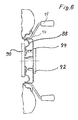
- the measuring device is suitable for measurements on such motor vehicles in which the measuring disks 8, 10 are non-impact at right angles to the axis of rotation of the wheels, i.e. can be mounted parallel to the wheel receiving surface, reference being made to FIG. 8.
- the wheel rims 88 have bores that provide access to the wheel receiving surface 90.
- the measuring disk 92 which corresponds in its function to the measuring disk 8, has bolts 94 on the side facing the wheel mounting plate, the length of which is the same within narrow tolerances and which correspond to the wheel rim 88 in the pitch circle and in the number of bores.
- the measuring disk 92 with the bolt 94 is then pressed with known clamping devices 96 with handles 98 against the wheel mounting plate 90 so that the bolts 94 abut.
- the measuring disk 92 is then exactly at right angles to the axis of rotation of the wheel, so that compensation for the rim runout by the movement of the wheel by 180 ° can be dispensed with.
- the storage of the measurement values from a first measurement run for a second measurement run is also dispensed with.
- the measuring device can be simplified overall in that instead of four angle measuring devices, only one angle measuring device is used, which is placed in order vertically and horizontally on the left front wheel and vertically and horizontally on the right front wheel, around the track - and fall measurements.
- An angle measuring device of the mechanical configuration, as described above, can serve for this purpose.
- the electronic equipment is then supplemented by a battery and a display instrument on the angle measuring device itself, so that the measured value can be read directly when the angle measuring device is attached.
- a changeover switch is required, which allows one and the same angle measurement to be displayed once as a positive deviation and once as a negative deviation depending on the vehicle side.
- a positive track of the left wheel in the angle measuring device 20 leads to a clockwise rotation of the head 46 relative to the housing 40 and with a positive track of the right wheel to a left turn.
- a positive camber of the left wheel leads to a left turn of the head 46 and a positive camber on the right wheel leads to a right turn.
- the polarity of the electrical circuit through the changeover switch is therefore the same for the measurements of: right track and left camber and left track and right camber.
- the correct position of the switch can be indicated by the appropriate labeling.
- the angle measuring devices are placed either vertically or horizontally between the measuring disks 8, 10 and the measuring plates 12, 14. In order to facilitate the vertical and horizontal alignment of the angle measuring devices, these can be provided with vials (not shown).
Landscapes
- Physics & Mathematics (AREA)
- General Physics & Mathematics (AREA)
- A Measuring Device Byusing Mechanical Method (AREA)
- Length Measuring Devices With Unspecified Measuring Means (AREA)
Priority Applications (1)
| Application Number | Priority Date | Filing Date | Title |
|---|---|---|---|
| AT85101020T ATE29293T1 (de) | 1984-02-08 | 1985-01-31 | Radstellungs-messvorrichtung. |
Applications Claiming Priority (2)
| Application Number | Priority Date | Filing Date | Title |
|---|---|---|---|
| EP84101304 | 1984-02-08 | ||
| EP84101304 | 1984-02-08 |
Publications (2)
| Publication Number | Publication Date |
|---|---|
| EP0158773A1 EP0158773A1 (de) | 1985-10-23 |
| EP0158773B1 true EP0158773B1 (de) | 1987-09-02 |
Family
ID=8191758
Family Applications (1)
| Application Number | Title | Priority Date | Filing Date |
|---|---|---|---|
| EP85101020A Expired EP0158773B1 (de) | 1984-02-08 | 1985-01-31 | Radstellungs-Messvorrichtung |
Country Status (4)
| Country | Link |
|---|---|
| US (1) | US4625419A (da) |
| EP (1) | EP0158773B1 (da) |
| DE (1) | DE3560537D1 (da) |
| DK (1) | DK55785A (da) |
Families Citing this family (8)
| Publication number | Priority date | Publication date | Assignee | Title |
|---|---|---|---|---|
| FR2621389B3 (fr) * | 1987-10-02 | 1989-12-22 | Renault Automation | Banc de mesure et reglage du parallelisme d'un train de roues de vehicule automobile |
| AU7578291A (en) * | 1990-08-15 | 1992-03-17 | Nichol Cong Huynh | Vehicle wheel alignment device |
| US5384965A (en) * | 1993-08-30 | 1995-01-31 | Chrysler Corporation | Vehicle tire-to-body coverage checking fixture and method of using same |
| DE19805102A1 (de) * | 1998-02-09 | 1999-08-12 | Hofmann Werkstatt Technik | Vorrichtung zur Einstellung der Spur an Kraftfahrzeugrädern |
| US6334263B1 (en) * | 1998-10-30 | 2002-01-01 | Spicer Technology, Inc. | Yoke straightening fixture |
| DE19855392C1 (de) * | 1998-12-01 | 2000-04-20 | Haweka Gmbh | Vorrichtung zur Befestigung einer Achsmeßeinrichtung an einer Felge eines Rades an einem Kraftfahrzeug |
| DE10310408A1 (de) * | 2003-03-07 | 2004-10-07 | Att Automotive Testing Technologies Gmbh | Vorrichtung zur Montage eines Achsmesskopfes am Fahrzeugrad |
| US20060185180A1 (en) * | 2005-02-22 | 2006-08-24 | Mackelvie Winston | Wheel alignment gauge |
Family Cites Families (14)
| Publication number | Priority date | Publication date | Assignee | Title |
|---|---|---|---|---|
| FR1317694A (da) * | 1963-05-10 | |||
| US2899753A (en) * | 1959-08-18 | Wheel-track gauge for motor vehicles | ||
| US2292969A (en) * | 1939-12-20 | 1942-08-11 | Albert P Peters | Aligning device |
| US2532593A (en) * | 1946-11-06 | 1950-12-05 | John H Bender | Means for measuring wheel alignment |
| DE1301915B (de) * | 1964-05-13 | 1969-08-28 | Polyprodukte Ag | Vorrichtung zum Pruefen der Fahrwerkgeometrie von Kraftfahrzeugen |
| CH424288A (de) * | 1965-01-05 | 1966-11-15 | Fibora Ag | Verfahren zur geometrischen Kontrolle des Fahrgestells bei Kraftfahrzeugen |
| US3546782A (en) * | 1968-06-25 | 1970-12-15 | Applied Power Ind Inc | Automotive wheel alining apparatus |
| GB1330404A (en) * | 1971-04-16 | 1973-09-19 | Chruchill Co Ltd V L | Wheel alignment gauging apparatus |
| US3793736A (en) * | 1972-07-21 | 1974-02-26 | Allitalia Import Export | Wheel alignment measuring apparatus |
| DE2358313A1 (de) * | 1973-11-23 | 1975-05-28 | Polyprudukte Ag | Verfahren und vorrichtung zur elektronischen achsvermessung |
| US4099333A (en) * | 1975-01-07 | 1978-07-11 | Gkn Transmissions Limited | Wheel alignment testing apparatus |
| US4302104A (en) * | 1979-10-02 | 1981-11-24 | Lee Hunter | Vehicle wheel alignment apparatus |
| DE3027089C2 (de) * | 1980-07-17 | 1986-11-27 | Mauser-Werke Oberndorf Gmbh, 7238 Oberndorf | Vorrichtung zum Messen und Korrigieren der Lenkgeometrie von Kraftfahrzeugen |
| US4457075A (en) * | 1980-12-15 | 1984-07-03 | Toyota Jidosha Kogyo Kabushiki Kaisha | Method and an apparatus for measuring wheel alignment of motor vehicles |
-
1985
- 1985-01-31 DE DE8585101020T patent/DE3560537D1/de not_active Expired
- 1985-01-31 EP EP85101020A patent/EP0158773B1/de not_active Expired
- 1985-02-07 DK DK55785A patent/DK55785A/da not_active Application Discontinuation
- 1985-02-08 US US06/700,019 patent/US4625419A/en not_active Expired - Fee Related
Also Published As
| Publication number | Publication date |
|---|---|
| US4625419A (en) | 1986-12-02 |
| DK55785D0 (da) | 1985-02-07 |
| DK55785A (da) | 1985-08-09 |
| DE3560537D1 (en) | 1987-10-08 |
| EP0158773A1 (de) | 1985-10-23 |
Similar Documents
| Publication | Publication Date | Title |
|---|---|---|
| EP2329221B1 (de) | Targetanordnung, satz von target-anordnungen und vorrichtung zur optischen achsvermessung | |
| EP2321618A1 (de) | Vorrichtung und verfahren zum bestimmen und einstellen der fahrwerksgeometrie eines fahrzeuges | |
| DE102007003086A1 (de) | Vorrichtung zum Messen der Fahrwerksgeometrie | |
| DE202016103584U1 (de) | Vorrichtung zur Kalibrierung eines in die Windschutzscheibe eines Fahrzeuges integrierten Umfeldsensors | |
| DE2413904A1 (de) | Steuermessgeraet fuer spitzenschleifmaschinen | |
| EP0158773B1 (de) | Radstellungs-Messvorrichtung | |
| DE3022073C2 (de) | Radstellungs-Meßvorrichtung | |
| DE3514759A1 (de) | Einrichtung zur vermessung der achsgeometrie an den radachsen von kraftfahrzeugen bei drehenden raedern | |
| DE1301915B (de) | Vorrichtung zum Pruefen der Fahrwerkgeometrie von Kraftfahrzeugen | |
| DE2313087C3 (de) | Vorrichtung zur Bestimmung der Taumelbewegung eines rotierenden Körpers gegenüber seiner tatsächlichen Rotationsachse | |
| DE2838399A1 (de) | Vorrichtung zur vermessung des lenkeinschlags und der radlast von raedern eines fahrzeugs, vorzugsweise eines kraftfahrzeugs | |
| DE2934411C2 (de) | Radstellungs-Meßvorrichtung. | |
| EP0270705B1 (de) | Vorrichtung zur Messung des Einschlagwinkels eines lenkbaren Rades eines Kraftfahrzeugs | |
| DE10333762A1 (de) | Fahrzeugprüfstand | |
| DE3432781A1 (de) | Messvorrichtung, insbesondere zur bestimmung der radstellungen eines kraftfahrzeugs im fahrbetrieb | |
| DE3608424A1 (de) | Vorrichtung zum ausrichten eines am rad eines kraftfahrzeuges angebrachten messgeraetehalters | |
| DE4330811C2 (de) | Radsatzausrichtverfahren für Radsatzbearbeitungsmaschinen und Radsatzausrichteinrichtung | |
| DE1548186A1 (de) | Verfahren und Einrichtung zum Ausrichten von Fahrzeugraedern | |
| DE2709682B2 (de) | Verfahren und Einrichtung zum Prüfen von Rotationskörpern, insbesondere Kfz-Reifen | |
| EP3631351B1 (de) | Untersatz zur fahrzeugvermessung mit referenzsystem | |
| DE3210318A1 (de) | Winkel- und spurmessvorrichtung fuer kfz-achsen bzw. -raeder | |
| DE102022000523A1 (de) | Vorrichtung und ein Verfahren zum Bestimmen der Radgeometrie eines Rades, insbesondere eines Rades eines Kraftfahrzeugs. | |
| DE3022071C2 (de) | Radstellungs-Meßvorrichtung | |
| DE3517595A1 (de) | Maschine zur automatischen pruefung der felgen von kraftfahrzeug-scheibenraedern | |
| DE2359227A1 (de) | Pruefgeraet fuer stroemungsmaschinenschaufeln |
Legal Events
| Date | Code | Title | Description |
|---|---|---|---|
| PUAI | Public reference made under article 153(3) epc to a published international application that has entered the european phase |
Free format text: ORIGINAL CODE: 0009012 |
|
| AK | Designated contracting states |
Designated state(s): AT DE FR GB IT |
|
| 17P | Request for examination filed |
Effective date: 19851111 |
|
| 17Q | First examination report despatched |
Effective date: 19861006 |
|
| R17C | First examination report despatched (corrected) |
Effective date: 19861007 |
|
| GRAA | (expected) grant |
Free format text: ORIGINAL CODE: 0009210 |
|
| AK | Designated contracting states |
Kind code of ref document: B1 Designated state(s): AT DE FR GB IT |
|
| REF | Corresponds to: |
Ref document number: 29293 Country of ref document: AT Date of ref document: 19870915 Kind code of ref document: T |
|
| REF | Corresponds to: |
Ref document number: 3560537 Country of ref document: DE Date of ref document: 19871008 |
|
| ET | Fr: translation filed | ||
| GBT | Gb: translation of ep patent filed (gb section 77(6)(a)/1977) | ||
| ITF | It: translation for a ep patent filed | ||
| PLBE | No opposition filed within time limit |
Free format text: ORIGINAL CODE: 0009261 |
|
| STAA | Information on the status of an ep patent application or granted ep patent |
Free format text: STATUS: NO OPPOSITION FILED WITHIN TIME LIMIT |
|
| 26N | No opposition filed | ||
| PGFP | Annual fee paid to national office [announced via postgrant information from national office to epo] |
Ref country code: FR Payment date: 19881230 Year of fee payment: 5 |
|
| PGFP | Annual fee paid to national office [announced via postgrant information from national office to epo] |
Ref country code: AT Payment date: 19890104 Year of fee payment: 5 |
|
| ITTA | It: last paid annual fee | ||
| PGFP | Annual fee paid to national office [announced via postgrant information from national office to epo] |
Ref country code: GB Payment date: 19890131 Year of fee payment: 5 |
|
| PGFP | Annual fee paid to national office [announced via postgrant information from national office to epo] |
Ref country code: DE Payment date: 19890213 Year of fee payment: 5 |
|
| PG25 | Lapsed in a contracting state [announced via postgrant information from national office to epo] |
Ref country code: GB Effective date: 19900131 Ref country code: AT Effective date: 19900131 |
|
| GBPC | Gb: european patent ceased through non-payment of renewal fee | ||
| PG25 | Lapsed in a contracting state [announced via postgrant information from national office to epo] |
Ref country code: FR Effective date: 19900928 |
|
| PG25 | Lapsed in a contracting state [announced via postgrant information from national office to epo] |
Ref country code: DE Effective date: 19901002 |
|
| REG | Reference to a national code |
Ref country code: FR Ref legal event code: ST |