EP0154290A2 - Garage en forme de roue - Google Patents
Garage en forme de roue Download PDFInfo
- Publication number
- EP0154290A2 EP0154290A2 EP85102145A EP85102145A EP0154290A2 EP 0154290 A2 EP0154290 A2 EP 0154290A2 EP 85102145 A EP85102145 A EP 85102145A EP 85102145 A EP85102145 A EP 85102145A EP 0154290 A2 EP0154290 A2 EP 0154290A2
- Authority
- EP
- European Patent Office
- Prior art keywords
- platforms
- ring
- wheel
- garage according
- axis
- Prior art date
- Legal status (The legal status is an assumption and is not a legal conclusion. Google has not performed a legal analysis and makes no representation as to the accuracy of the status listed.)
- Withdrawn
Links
Images


Classifications
-
- E—FIXED CONSTRUCTIONS
- E04—BUILDING
- E04H—BUILDINGS OR LIKE STRUCTURES FOR PARTICULAR PURPOSES; SWIMMING OR SPLASH BATHS OR POOLS; MASTS; FENCING; TENTS OR CANOPIES, IN GENERAL
- E04H6/00—Buildings for parking cars, rolling-stock, aircraft, vessels or like vehicles, e.g. garages
- E04H6/08—Garages for many vehicles
- E04H6/12—Garages for many vehicles with mechanical means for shifting or lifting vehicles
- E04H6/16—Garages shaped as a wheel or drum rotatable about a horizontal axis
Definitions
- the invention relates to a bicycle garage.
- Bicycle garages are known in many embodiments. A distinction can be made between two basic systems.
- the first system includes the bike garages, in which the platforms are suspended in the manner of gondolas between two turnstiles connected by their horizontal axis of rotation, and the ramp of the entrance and exit and, accordingly, the lanes of the platforms are in the radial direction of the wheel extend garage.
- the disadvantage of these wheelbase garages is that they allow only a few platforms and a correspondingly small amount of storage space in comparison to their space requirements, with a high level of structural complexity.
- the platforms have a radial or, in other words, crossways to the axis of rotation
- three platforms are provided one above the other with six radial struts assigned to each pair of struts.
- the axis of rotation of the radial struts on one broad side is arranged higher than the axis of rotation of the opposite struts on the other side.
- a gear transmission is present between the two axes of rotation.
- the pivot axes on opposite sides of the three platforms are also offset by an amount which corresponds to the aforementioned offset of the axes of rotation.
- the second system includes those bike garages in which the platforms are also arranged between two turnstiles, which are connected to each other by their horizontal axis of rotation, the ramp of the entrance or exit and accordingly the lanes of the platforms also in the axial direction of the wheel garage or in in other words, extend parallel to the axis of rotation.
- These bike garages have the advantage that the space is used to a large extent take place karm.
- G to the wheel Arage after the second-mentioned system also includes those according to DE-AS 27 06 to 983.
- the axis of rotation lies in the level of the entrance and exit, which is only available on one side.
- the axes of rotation of the platforms are arranged at a respective distance from the end of the legs forming the turnstile, so that the entry or exit is only possible in the plane and thus to the side of the axis of rotation.
- the previously known bike garage only allows up to four platforms for parking vehicles.
- the second-mentioned system also includes the wheel garage according to US Pat. No. 2,706,054, from which the present invention is based.
- a wheel garage is described in which a cage provided with radial struts can be rotated about a horizontal central longitudinal axis and the cage carries platforms for passenger cars parked thereon, which can be pivoted about a horizontal pivot axis assigned to each platform so that each platform is always in one remains horizontal extension and for this purpose each pivot axis of a platform is provided at its end with a radially projecting arm and these arms are pivotally connected at their ends by rods which are closed to form a ring.
- the circumference of the cage is closed by two rings which run on support bearings made of rollers. In the middle of the outer circumference there is a ring gear that is driven by an electric motor.
- the platforms are present within tubes which can be pivoted about the central longitudinal axis of the tube, so that the platforms E which are at a considerable distance below these pivot axes maintain their constant horizontal position.
- These supporting rollers are located between the tubes and are attached to a special support frame.
- the bicycle garage can only be manufactured with considerable construction effort. The disadvantage is that it does not allow passage because the tubes are only open on one side. Another disadvantage is that at least three entry routes must be left free. The bike garage can only be set up at the middle height shown.
- the present invention is based on the object of creating a wheel garage which, with a simple construction and small space requirement, enables a large number of platforms, the longitudinal extent of which can be parallel to the central axis designed as an axis of rotation and also transversely thereto, and an unobstructed passage parallel to the axis of rotation in allows different altitudes.
- the solution according to the invention achieves a wheel garage which enables a large number of platforms with a small space requirement, the platforms being accessible in the radial direction to the axis of rotation or in the axial direction to the axis of rotation. At the same time, continuous travel can take place in the case of platforms which can be driven in the axial direction to the axis of rotation.
- wheeled garages with three, four, five, but also six or eight platforms can be produced.
- multiple platforms can form a unit in the case of platforms which are directed radially and thus transversely to the axis of rotation of the wheel garage.
- the central longitudinal axis is designed as a physical axis, which has support bearings at both ends, is not only the basis for a structurally simple structural design of the wheel garage, but also the basis for the wheel garage to be able to arrange the invention in many different structures. So it can be arranged in a pit. It can also be arranged within a building. For example, the axis of rotation can be arranged in the plane of the driveway, but also below or above the driveway.
- outrigger arms extending from the pivot axes of the platforms run parallel to the horizontal plane or, if they are arranged at a small and therefore hardly noticeable distance below the platforms, ensures one with platforms whose longitudinal extension runs parallel to the axis of rotation Arrangement that does not hinder the passage of one platform below another platform.
- cantilevers are arranged on the pivot axes of the platforms, the ends of which are connected by a ring which encompasses the central longitudinal axis of the turnstile, ensures in a simple manner the extension of the platforms which always remains in the horizontal plane.
- the arms on the platforms with the guide pins or rollers, which are connected to a rotating ring, can be arranged on both ends of a wheel garage without the continuous access via at least three platforms, which are arranged axially to the axis of rotation, being impeded.
- the solution according to the invention is so torsionally rigid with a simple design of the wheel garage that only on one end of the cage are the cantilevers on the pivot axes of the platforms and at the ends of the guide rollers or pins which engage in the circumferential ring. It is preferably a ring which is rotatably mounted on the foundation or the like scaffold.
- the pivot axes of the platforms are located just above the platforms. This ensures that they do not hinder continuous access to a platform.
- the pivot axes of the platforms lie in their planes, the ends of the platforms formed from sheet metal being provided with pivot axes which are mounted at the ends of the associated radial struts.
- the solution according to the invention allows three platforms to be arranged one above the other as a structural unit with an assigned pivot axis.
- the solution according to the invention also makes it possible for a plurality of radar garages to be arranged next to one another both in the radial entry and exit to the axis of rotation and in the case of axial entry and exit and in the extent coaxial with the axis of rotation.
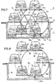
- the axis of rotation is arranged below the carriageway 16 in a pit 17 which has the two opposite side walls 18, 18a and the two end walls 19, 19a.
- the bike garage is provided with a roof 20.
- the two platforms 14 and 14a arranged at the top lie in the plane of the access 16 and that an unobstructed passage is therefore possible for the platform 14 because doors or gates 20, 20a are present. It is advantageous that only doors or gates 19, 19a are provided for the platform 14 on the left in the drawing, although the platform 14a would also make it possible to enter and exit in a continuous direction.
- Figures 3 and 4 show that when the axis of rotation 11 is arranged at the height of the access 16, both vehicles located on the platforms 14b and 14c can be climbed, likewise preferably only one of these two platforms 14b and 14c with a door or one Gate for the entrance or exit is provided.
- Figures 5 and 6 show that the axis of rotation 11 of the wheel cross or the cage is arranged so deep within the pit that the two upper platforms 14, 14a are accessible, in this case the access in the direction of arrow 22 and the exit in the opposite arrow direction 22a takes place.
- Figures 1 to 6 are intended to demonstrate that the bicycle garage according to the invention is suitable to meet diverse spatial requirements.
- Figures 1 to 6 show the principle that the platforms 14, 14a, etc. extend in the axial direction of the axis of rotation 11 formed as a central longitudinal axis and thus cause the axial entry or exit.
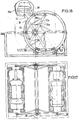
- FIG. 7 Further details on the structure of the wheel garage shown in FIGS. 1 to 6 can be found in FIG. 7.
- the axis of rotation 11 is shown, which according to FIG. 10 is provided with radially projecting disks 23 and 24 at each end, which according to FIG Shape of two disks 23 and 23a or 24 and 24a are present, between which the six radial struts 12, 12a, 12b, etc. are arranged.
- These radial struts 12 are connected to about half their length with cross struts 25, 25a, 25b etc., which form a hexagonal.
- FIG. 7 shows in the lower left part that the platforms 14 can be displaced outward in the indicated double arrow direction and thus in their plane and are thereby moved and also carried by the respectively adjacent conveying devices 41, 41a. This makes it possible for the car shown in the bottom left view to allow an exit in the usual direction of travel even in a pit.
- FIGS. 7 and 8 show that cantilevers 27 are arranged on these pivot axes 13, 13a etc. in their horizontal plane and in the view to the right, which engage in a ring at their ends.
- FIG. 7 shows the radial struts 12 with the transverse stiffeners and the pivot axes 13 with the platforms 14.
- the arms 27 have at their free ends guide pins 28 which are pivotally connected to a ring 29.
- this ring is a rotating circular ring, the center M of which lies at such a distance laterally next to the axis of rotation 11 of the wheel garage, which corresponds to the length of a bracket 27.
- the ring 29 is, as can be seen in detail from FIGS. 12 to 14, mounted on the end wall 19 of the pit or the like fixed frame and guided between an upper roller 35 and a lower roller 35a, which are fastened to the plate 40, which in turn is attached to the wall 19 of the pit or the like scaffolding.
- FIG. 14 shows that the pin 28 arranged at the outer end of the arm 27 engages in an associated bore of the rotating guide ring 29. It is understandable that a ball bearing, not shown, can be used.
- the above-described rotating guide ring 29 is a particularly advantageous, simple and safe solution.
- Figure 7 shows that the ring 29 is provided on its circumference, advantageously on its outer circumference with drive means in the form of a toothing with teeth 42, in which a locally available drive 43 engages, which according to the embodiment consists of a rotating chain 44 and deflection rollers and the Electric motor 45 is made.
- the rotation of the wheel garage by the drive of the ring 29, which at the same time ensures the always horizontal position of the platforms 14 by the arrangement of the arms 27, is a particularly advantageous, inexpensive and space-saving solution.
- the boom has at its free end two guides 47, 47a in the form of screws, the shafts of which are screwed into associated threaded bores.
- a guide piece 48 is slidably mounted on the shafts and has the pin 28 which engages in an associated bore of the ring 29, as shown in FIG. 14. The heads of the screws 47, 47a secure the maximum displacement and can therefore lead to a certain setting.
- Figure 9 shows the modified solution.
- the arms 27, 27a, etc. are pivotable via axes 28, 28a, 28b, etc.
- Bars 29 ', 29a', 29b ', etc. which are six pieces and thus form a hexagonal.
- This thus forming a polygon ring 29 'from the rods 30 also surrounds the axis of rotation 11 with a center 14 which is arranged laterally next to the axis of rotation 11 and in its horizontal plane and at a distance which corresponds to the length of a boom 27.
- the systems are surrounded by rollers which engage in a rail 34 which is attached to the wall 19 as a circular sector.
- the stationary rail 34 can also be closed to form a ring into which the pins 28 surrounded by a ball bearing engage.
- Fig. 10 it is also shown that for the purpose of stiffening there are struts 31 extending from each pipe end, which protrude radially and are connected to the radial struts.
- the rods 30 can also be ropes because they are only subjected to tension.
- Figure 10 shows that the axis of rotation is provided at both ends with bearings 32, 32a, which rest on associated foundations 33, 33a.
- these foundations 33 can also be designed in any other way.
- they can also be components of scaffolding, which represent storage areas for the bearings 32 above the ground, provided that, as can be the case with parking garages, the access is formed by ramps.
- the axis of rotation consisting of a tube makes it possible to arrange the radial struts and, if present, the rods 29 in a respective tube half for the purpose of transport.
- FIG. 10 shows that the pivot axis 13 assigned to each platform is arranged in the plane of the platform and is short in length at the ends of the platforms formed from sheet metal and the arms 27 with the rotating ring 29 are arranged only on one end face.
- Figure 16 shows a modification in such a way that the radial struts 12, 12a, etc. are connected in addition to the cross struts 25 by diagonal struts 26, 26a.
- the aforementioned radial, transverse and diagonal struts are advantageously screwed together so that the wheel garage has a small volume for the purpose of being transported to the construction site.
- the platform 14 is provided with a protective housing 30 which has a sliding door 30a.
- FIG. 18 shows a wheel garage of the design according to the invention, in which the above-described axis of rotation 11 is also supported at both ends. It has six radial struts 12, 12a, 12b etc., at the ends of which the pivot axes 13, 13a etc. are arranged for platforms. The platforms extend in their longitudinal direction transverse to the axis of rotation 11, so that radial entry and exit, as shown in the direction of the arrow, takes place.
- FIG 18 shows that three platforms 14 as platforms 14 ', 14 "and 14'” are arranged as a structural unit with a single assigned pivot axis 13, which are connected to one another by side walls 37 and 37a as shown in Figure 19 and the associated Swivel axis 13 consists of two sections 13 'and 13 ", each of which extends in a coaxial extension in the region of the radial struts 12', 12" to the two side walls 37, 37a.
- FIG. 18 shows that the platforms 14 ', 14 "and 14'" are surrounded by a protective housing 30.
- Figure 20 shows that there are several bicycle garages next to each other in coaxial extension.
- the individual wheel garage can accommodate a large number of motor vehicles despite the small space requirement and that the individual wheel garage is so narrow that several wheel garages can be arranged side by side in a small space.
- all of the drawings, in particular FIGS. 17 and 18, show that in the case of individual wheeled garages, but also in the case of a plurality of wheeled garages arranged next to one another, the axes of rotation of the wheeled garages lie in coaxial extension. This enables simple statics.
- FIGS. 17 and 18 show that in the case of individual wheeled garages, but also in the case of a plurality of wheeled garages arranged next to one another, the axes of rotation of the wheeled garages lie in coaxial extension. This enables simple statics.
- wheel garages can also be present coaxially one behind the other in the wheel garages according to FIGS. 2, 4 and 6. These can then be rotated individually so that passage through platforms arranged one behind the other is possible is. This is the case with the respective position of the platforms at the height of the axis of rotation 11 and above, as can be seen from FIG. 1.
- FIG. 23 shows the space-saving arrangement of a bicycle garage with a narrow entrance and a turntable 47.
- FIG. 24 shows that the bicycle garage can also be used as a lift in order to be able to reach several parking levels 48, 48a, 48b of a parking garage arranged one above the other.
- Figure 25 shows that the wheel garage is mounted on a frame 49.
- FIG. 26 shows a platform made of concrete 50 with a reinforcement 51, which is hollow in the area of the two lanes and has an upward curvature in the area in between. At the end faces there are transverse walls 51 which support the pivot axes 13, 13a.
- Figure 27 shows a platform made of sheet steel, which is also formed in the area of the lanes as a hollow body. At the end faces there are also transverse walls which carry the swivel axes 13 of short length.
Landscapes
- Engineering & Computer Science (AREA)
- Architecture (AREA)
- Mechanical Engineering (AREA)
- Civil Engineering (AREA)
- Structural Engineering (AREA)
- Wind Motors (AREA)
- Gates (AREA)
Applications Claiming Priority (6)
| Application Number | Priority Date | Filing Date | Title |
|---|---|---|---|
| GR73955 | 1984-02-29 | ||
| GR73955A GR73759B (fr) | 1984-02-29 | 1984-02-29 | |
| DE3414839 | 1984-04-19 | ||
| DE3414839A DE3414839A1 (de) | 1984-02-29 | 1984-04-19 | Radgarage |
| GR80510 | 1984-10-01 | ||
| GR80510A GR80510B (en) | 1984-10-01 | 1984-10-01 | Rotating mechanic garage |
Publications (2)
| Publication Number | Publication Date |
|---|---|
| EP0154290A2 true EP0154290A2 (fr) | 1985-09-11 |
| EP0154290A3 EP0154290A3 (fr) | 1987-04-01 |
Family
ID=27191908
Family Applications (1)
| Application Number | Title | Priority Date | Filing Date |
|---|---|---|---|
| EP85102145A Withdrawn EP0154290A3 (fr) | 1984-02-29 | 1985-02-27 | Garage en forme de roue |
Country Status (1)
| Country | Link |
|---|---|
| EP (1) | EP0154290A3 (fr) |
Cited By (6)
| Publication number | Priority date | Publication date | Assignee | Title |
|---|---|---|---|---|
| EP0292619A2 (fr) * | 1987-05-29 | 1988-11-30 | Giorgio Piacenza | Garage d'automobiles à stockage mécanique à niveaux multiples |
| GB2237799A (en) * | 1989-10-23 | 1991-05-15 | Toko Rehome Kabushiki Kaisha | Vehicle parking apparatus |
| DE4133672A1 (de) * | 1991-10-11 | 1993-04-22 | Romuald Bartocha | Drehbuehnenvorrichtung |
| WO2004022884A1 (fr) * | 2002-09-03 | 2004-03-18 | Youcai Song | Dispositif de stationnement a carrousel pour automobiles |
| CN105587145A (zh) * | 2016-02-01 | 2016-05-18 | 安徽工程大学 | 卧轴转轮式立体车库停车位规划方法 |
| CN113565352A (zh) * | 2021-07-16 | 2021-10-29 | 青岛德盛利立体停车设备有限公司 | 一种停车设备用同步机构 |
Citations (9)
| Publication number | Priority date | Publication date | Assignee | Title |
|---|---|---|---|---|
| US1867675A (en) * | 1930-12-04 | 1932-07-19 | Daniel C Ingold | Storage garage |
| US2706054A (en) * | 1952-01-05 | 1955-04-12 | Thomas E Morrison | Automobile storage structure |
| GB817842A (en) * | 1956-11-17 | 1959-08-06 | Christabel May Crawley | Improvements in or relating to car parking and storage devices |
| GB854416A (en) * | 1958-06-09 | 1960-11-16 | Josef Schulte | Improvements in or relating to devices for parking vehicles |
| US3077994A (en) * | 1960-08-05 | 1963-02-19 | Robert O Lane | Vehicle parking apparatus |
| GB997728A (en) * | 1963-01-08 | 1965-07-07 | Kyosuke Mori | Garage for use in car parks |
| FR1436773A (fr) * | 1965-03-12 | 1966-04-29 | Garage pour véhicules automobiles | |
| DE2706983B2 (de) * | 1977-02-18 | 1978-12-14 | Bernd 4250 Bottrop Vienken | Radgarage |
| US4364703A (en) * | 1980-03-14 | 1982-12-21 | Pai Yang Kuang | Rotary parking structure for passenger cars |
-
1985
- 1985-02-27 EP EP85102145A patent/EP0154290A3/fr not_active Withdrawn
Patent Citations (9)
| Publication number | Priority date | Publication date | Assignee | Title |
|---|---|---|---|---|
| US1867675A (en) * | 1930-12-04 | 1932-07-19 | Daniel C Ingold | Storage garage |
| US2706054A (en) * | 1952-01-05 | 1955-04-12 | Thomas E Morrison | Automobile storage structure |
| GB817842A (en) * | 1956-11-17 | 1959-08-06 | Christabel May Crawley | Improvements in or relating to car parking and storage devices |
| GB854416A (en) * | 1958-06-09 | 1960-11-16 | Josef Schulte | Improvements in or relating to devices for parking vehicles |
| US3077994A (en) * | 1960-08-05 | 1963-02-19 | Robert O Lane | Vehicle parking apparatus |
| GB997728A (en) * | 1963-01-08 | 1965-07-07 | Kyosuke Mori | Garage for use in car parks |
| FR1436773A (fr) * | 1965-03-12 | 1966-04-29 | Garage pour véhicules automobiles | |
| DE2706983B2 (de) * | 1977-02-18 | 1978-12-14 | Bernd 4250 Bottrop Vienken | Radgarage |
| US4364703A (en) * | 1980-03-14 | 1982-12-21 | Pai Yang Kuang | Rotary parking structure for passenger cars |
Cited By (8)
| Publication number | Priority date | Publication date | Assignee | Title |
|---|---|---|---|---|
| EP0292619A2 (fr) * | 1987-05-29 | 1988-11-30 | Giorgio Piacenza | Garage d'automobiles à stockage mécanique à niveaux multiples |
| EP0292619A3 (en) * | 1987-05-29 | 1989-05-31 | Giorgio Piacenza | Mechanical-storage multi-level carpark |
| GB2237799A (en) * | 1989-10-23 | 1991-05-15 | Toko Rehome Kabushiki Kaisha | Vehicle parking apparatus |
| GB2237799B (en) * | 1989-10-23 | 1993-09-15 | Toko Rehome Kabushiki Kaisha | Vehicle parking apparatus of circulatory,vertically-accommodating type |
| DE4133672A1 (de) * | 1991-10-11 | 1993-04-22 | Romuald Bartocha | Drehbuehnenvorrichtung |
| WO2004022884A1 (fr) * | 2002-09-03 | 2004-03-18 | Youcai Song | Dispositif de stationnement a carrousel pour automobiles |
| CN105587145A (zh) * | 2016-02-01 | 2016-05-18 | 安徽工程大学 | 卧轴转轮式立体车库停车位规划方法 |
| CN113565352A (zh) * | 2021-07-16 | 2021-10-29 | 青岛德盛利立体停车设备有限公司 | 一种停车设备用同步机构 |
Also Published As
| Publication number | Publication date |
|---|---|
| EP0154290A3 (fr) | 1987-04-01 |
Similar Documents
| Publication | Publication Date | Title |
|---|---|---|
| DE1271369B (de) | Vorrichtung zum Abstellen von Kraftfahrzeugen od. dgl. | |
| DE1929305C3 (de) | Rampe zur abwechselnden Verbindung einer Zufahrt mit mehreren, übereinander angeordneten Stockwerkböden einer Garage od.dgl | |
| EP0447825B2 (fr) | Pont démontable à deux voies avec une poutre de lancement située entre les voies | |
| DE1965142A1 (de) | Einrichtung zum Parken zweier Fahrzeuge uebereinander | |
| EP0154290A2 (fr) | Garage en forme de roue | |
| DE4009973C2 (fr) | ||
| EP0008082B1 (fr) | Garage pour garer les véhicules l'un au-dessus de l'autre | |
| EP0451717B1 (fr) | Table élévatrice pour surmonter une différence de niveau d'une voie de transport | |
| EP0684354A2 (fr) | Dispositif élévateur pour garages | |
| DE4418496C1 (de) | Hubvorrichtung für Garagen | |
| EP0514387A1 (fr) | Dispositif de stockage vertical, notamment pour vehicule. | |
| DE3414839A1 (de) | Radgarage | |
| EP0195370A2 (fr) | Ascenseur de transport de personnes ou de charges avec une cabine en forme d'anneau | |
| DE2902918B1 (de) | Kastenaufbau,insbesondere fuer Tiertransportfahrzeuge | |
| DE2703713A1 (de) | Parkeinrichtung fuer kraftfahrzeuge | |
| EP0572928A1 (fr) | Installation de parking | |
| DE4344032C2 (de) | Karusselldrehtür | |
| DE2913661A1 (de) | Abstellvorrichtung fuer kraftfahrzeuge | |
| DE2914350A1 (de) | Aufzugseinrichtung | |
| DE2941775C2 (de) | Mobile Brechanlage für Tagebaubetriebe | |
| EP0490094B1 (fr) | Pont démontable et véhicule pour la pose du pont | |
| CH687405A5 (de) | Parkiersystem. | |
| DE19825691C1 (de) | Einrichtung zum Be- und Entladen von Fahrzeugen einer Vergnügungsbahn | |
| EP0881343A1 (fr) | Appareil de parcage pour automobiles avec au moins deux places de parking superposées | |
| AT262150B (de) | Rollsteig |
Legal Events
| Date | Code | Title | Description |
|---|---|---|---|
| PUAI | Public reference made under article 153(3) epc to a published international application that has entered the european phase |
Free format text: ORIGINAL CODE: 0009012 |
|
| AK | Designated contracting states |
Designated state(s): AT BE CH DE FR GB IT LI LU NL SE |
|
| PUAL | Search report despatched |
Free format text: ORIGINAL CODE: 0009013 |
|
| AK | Designated contracting states |
Kind code of ref document: A3 Designated state(s): AT BE CH DE FR GB IT LI LU NL SE |
|
| STAA | Information on the status of an ep patent application or granted ep patent |
Free format text: STATUS: THE APPLICATION IS DEEMED TO BE WITHDRAWN |
|
| 18D | Application deemed to be withdrawn |
Effective date: 19870228 |