EP0153733A2 - Offsetdruckeinrichtung - Google Patents
Offsetdruckeinrichtung Download PDFInfo
- Publication number
- EP0153733A2 EP0153733A2 EP85102104A EP85102104A EP0153733A2 EP 0153733 A2 EP0153733 A2 EP 0153733A2 EP 85102104 A EP85102104 A EP 85102104A EP 85102104 A EP85102104 A EP 85102104A EP 0153733 A2 EP0153733 A2 EP 0153733A2
- Authority
- EP
- European Patent Office
- Prior art keywords
- printing
- support
- plate
- roller
- printing device
- Prior art date
- Legal status (The legal status is an assumption and is not a legal conclusion. Google has not performed a legal analysis and makes no representation as to the accuracy of the status listed.)
- Withdrawn
Links
- 238000007645 offset printing Methods 0.000 title abstract description 5
- 238000007639 printing Methods 0.000 claims abstract description 153
- 230000000295 complement effect Effects 0.000 claims abstract description 8
- 239000004033 plastic Substances 0.000 claims description 6
- 230000002093 peripheral effect Effects 0.000 claims description 2
- 239000000969 carrier Substances 0.000 description 4
- 238000000034 method Methods 0.000 description 4
- 238000010276 construction Methods 0.000 description 2
- 230000000694 effects Effects 0.000 description 2
- 238000004519 manufacturing process Methods 0.000 description 2
- RYGMFSIKBFXOCR-UHFFFAOYSA-N Copper Chemical compound [Cu] RYGMFSIKBFXOCR-UHFFFAOYSA-N 0.000 description 1
- 239000011324 bead Substances 0.000 description 1
- 210000000078 claw Anatomy 0.000 description 1
- 238000004140 cleaning Methods 0.000 description 1
- 230000006835 compression Effects 0.000 description 1
- 238000007906 compression Methods 0.000 description 1
- 229910052802 copper Inorganic materials 0.000 description 1
- 239000010949 copper Substances 0.000 description 1
- 230000000881 depressing effect Effects 0.000 description 1
- 238000005530 etching Methods 0.000 description 1
- 238000007646 gravure printing Methods 0.000 description 1
- 238000002347 injection Methods 0.000 description 1
- 239000007924 injection Substances 0.000 description 1
- 238000012423 maintenance Methods 0.000 description 1
- 239000000463 material Substances 0.000 description 1
- 230000000149 penetrating effect Effects 0.000 description 1
- 238000002360 preparation method Methods 0.000 description 1
- 238000005096 rolling process Methods 0.000 description 1
- 238000003860 storage Methods 0.000 description 1
- 230000008719 thickening Effects 0.000 description 1
Images
Classifications
-
- B—PERFORMING OPERATIONS; TRANSPORTING
- B41—PRINTING; LINING MACHINES; TYPEWRITERS; STAMPS
- B41L—APPARATUS OR DEVICES FOR MANIFOLDING, DUPLICATING OR PRINTING FOR OFFICE OR OTHER COMMERCIAL PURPOSES; ADDRESSING MACHINES OR LIKE SERIES-PRINTING MACHINES
- B41L17/00—Lithographic printing apparatus for office or other commercial purposes
- B41L17/08—Lithographic printing apparatus for office or other commercial purposes for offset printing
- B41L17/10—Lithographic printing apparatus for office or other commercial purposes for offset printing with flat printing surfaces, e.g. co-operating with travelling offset cylinders
-
- B—PERFORMING OPERATIONS; TRANSPORTING
- B41—PRINTING; LINING MACHINES; TYPEWRITERS; STAMPS
- B41F—PRINTING MACHINES OR PRESSES
- B41F3/00—Cylinder presses, i.e. presses essentially comprising at least one cylinder co-operating with at least one flat type-bed
- B41F3/18—Cylinder presses, i.e. presses essentially comprising at least one cylinder co-operating with at least one flat type-bed of special construction or for particular purposes
- B41F3/30—Cylinder presses, i.e. presses essentially comprising at least one cylinder co-operating with at least one flat type-bed of special construction or for particular purposes for lithography
- B41F3/34—Cylinder presses, i.e. presses essentially comprising at least one cylinder co-operating with at least one flat type-bed of special construction or for particular purposes for lithography for offset printing
Definitions
- the invention relates to a printing device comprising a printing roller covered with a rubber blanket, a flat printing plate support, means for holding the printing plate thereon - in the direction of movement of the printing roller (printing direction) - behind the printing plate support, a printing medium support, means for holding the printing medium on the same and directional stops Aligning the printing plate and printing medium on the respective support.
- the invention has for its object to design a printing device of the type mentioned so that it enables good print quality even with multi-color printing on the one hand, on the other hand is simple in construction and handling and can be produced at a low price, so that the printing device for young people and hobby printer can be used.
- the printing plate support and the printing support support on a common support plate between two parallel to the printing direction, ver with the support plate tied racks are arranged so that the pressure roller can be lifted freely from the carrier plate, each has at its axial ends a toothed ring intended for engagement with a rack and is freely rotatably mounted on a shaft provided with handles, and that on the carrier plate - in the printing direction - at least one projection or one complementary recess are provided in front of the printing plate support and on the printing roller, which engage with one another in the starting position of the printing roller.
- the printing unit according to the invention can be dispensed with initially using the otherwise usual inking unit and dampening unit. Because the pressure roller can be removed freely from the carrier plate, there is no need for complicated and expensive storage of the pressure roller on a carriage which can be moved relative to the carrier plate. It is crucial for a good print quality, however, that the printing roller can always be brought back exactly to its starting position without great effort, so that the image on the rubber blanket of the printing roller is not displaced and thus becomes blurred even if the printing plate overflows several times. By assigning a projection arranged on the carrier plate or the pressure roller and a complementary depression on the other part in each case, the pressure roller can be brought back to its original position quickly and easily after lifting off the toothed racks.
- the pressure plate support, the pressure support support and the toothed racks are formed in one piece with the support plate, the entire arrangement preferably being made of plastic.
- an embodiment is more versatile in which the printing plate support and the printing support support are designed as plates that can be removed from the carrier plate, wherein means for positioning the same on the carrier plate are provided on the carrier plate and / or the plates.
- the printing device with inserted plate can be used as a pure offset printing device, the user can place a linocut or a copper plate for an etching on the carrier plate after removing the printing plate support, whereby both direct (reverse-side impression) and indirect (correct-side impression) printing can.
- the user after removing the print carrier plate, the user can also insert print carriers with a greater thickness than paper.
- the protrusion is formed by a centering strip on the carrier plate extending transversely to the printing direction and the depression is formed by an axially parallel centering groove on the circumference of the pressure roller which is at least approximately complementary in cross section.
- the centering strip preferably has an at least approximately triangular cross-sectional profile with a flat triangle side intended for bearing on the carrier plate and two convexly curved flanks. This shape of the centering bar ensures, on the one hand, that the pressure roller is exactly centered even when placed inaccurately on the centering bar and, on the other hand, that the printing roller is without Disability and thus can be rolled away smoothly from their starting position.
- the centering strip can be removed from the carrier plate and can be fixed to it by means of at least two pins.
- This has the advantage that the centering bar can be used at the same time as a holder and as a directional stop for the pressure plate by the pins penetrating corresponding holes in the pressure plate and the pressure plate being clamped between the centering bar and the carrier plate.
- the diameter and the mutual spacing of the pins correspond to the corresponding dimensions of commercially available perforators for office purposes.
- Such a punch can be found in practically every household or can be purchased for little money. The perforation of the printing plates with such a punch ensures an absolutely secure hold and a secure alignment of the printing plate on the printing plate support.
- a clamping strip directed transversely to the printing direction is preferably arranged between the printing plate support and the printing medium support, which can be pivoted about an axis parallel to the printing direction in the support plate and can be pretensioned into its clamping position.
- the terminal strip can also serve as a directional stop for aligning the print carrier in the print direction. It is therefore sufficient to add a directional stop for an alignment of the print Carrier to provide transversely to the printing direction, this latter directional stop can be formed by a small projection on the print carrier support.
- the central distance between the clamping strip and the centering strip in the printing device according to the invention is expediently equal to the circumference of the printing roller, the width of the section of the clamping strip protruding above the printing medium support being smaller than in the printing direction is the width of the centering groove in the pressure roller.
- the easiest way to achieve an axial alignment of the pressure roller or an alignment of the pressure roller transversely to the printing direction is that the pressure roller in each case has a guide flange projecting radially beyond the gear rim axially within the gear rims.
- the handles on the axial ends of the roller shaft have a larger diameter than the diameter of the guide flanges, this only applies to relatively small roller diameters.
- these handles are easy to hold when the pressure roller is guided over the printing plate support and the printing medium support with a certain pressure.
- the printing roller can thus be placed on any surface without the risk that the base is soiled by printing ink on the rubber blanket or vice versa the image on the platen roller may be blurred.
- Means can be provided on the circumference of the handles to prevent the pressure roller from automatically rolling on a support.
- the handles to have at least one flat, axially parallel surface on their circumferential surface, the radial distance from the roller axis being greater than the radius of the guide flanges.
- This also has the advantage that the roller can be placed on a pad and rotated, for example when cleaning the rubber blanket, while the handles rest on the pad.
- the movement path of the printing roller preferably rises continuously and slightly at least at the end sections of the toothed racks projecting beyond the printing medium support in the printing direction. This can be achieved, for example, by reducing the tooth depth of the toothed racks in these end sections.
- the tip circle diameter of the toothed rings is expediently slightly larger than the outside diameter of the printing roller covered with a rubber blanket. This has the effect that, due to the different radii of the toothed rings and the blanket surface and the different peripheral speeds based thereon, the printing medium is tensioned in the printing direction, so that the printing medium only has to be clamped at one end and that a somewhat wavy printing medium is also smoothed out during the printing process.
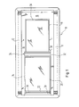
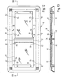
- FIG. 1 shows a rectangular support plate, generally designated 10, which has a rack 12 on its upper side along its longitudinal edges. Between the toothed racks 12, a rectangular pressure plate support 14 and a likewise rectangular pressure support support 16 - viewed in the longitudinal direction of the toothed racks 12 - are arranged one behind the other in the form of plate-shaped elevations with surfaces of the same height.
- the supports or tables 14 and 16 are each separated from the toothed racks 12 or the transverse edges of the carrier plate 10 by recessed areas 18.
- the carrier plate 10, the toothed racks 12, the pressure plate support 14 and the pressure support support 16 are made in one piece as a plastic injection molded part.
- the centering strip consists of a hollow or also filled plastic part which, according to FIG. 5, has an approximately triangular cross section with a flat base surface 24 and convexly curved side surfaces or flanks 26. The apex between the two convexly curved side surfaces 26 can, as shown in FIG. 5, be slightly flattened.
- the centering bar 22 On its base surface 24, the centering bar 22 carries two pins 28, which are intended for engagement in complementary bores 30, not shown, on the left edge of the pressure plate support 14.
- the diameter and the distance of the pins 28 are chosen so that they correspond to the corresponding dimensions of a conventional office punch. This makes it possible to punch the printing plate 20 with such a punch and not only immovably hold it with the aid of the centering strip 22 and the pin 28, but also to hold it in a certain orientation relative to the printing plate support 14. This perforation can also be used in the preparation of a set of printing plates for multi-color printing in order to achieve the congruence of the motif on the printing plates, so that these result in exactly superimposed printed images after being clamped onto the printing plate support 14.
- a clamping strip 34 is arranged in a recess 32 between the printing plate support 14 and the printing support support 16, which is shown in more detail in FIGS. 9 to 11 and serves to hold the printing support 36, in most cases a piece of paper, on the print support support 16.
- the clamping strip 34 consists of an approximately semi-cylindrical central section 38 which is connected along its one longitudinal edge to an actuating strip 40 and along its other longitudinal edge to a claw 42.
- the terminal block 34 is mounted with its central portion 38 in a circular arcuate trough 44 of the recess 32 between the pressure plate support 14 and the pressure carrier support 16, so that it by depressing the operating bar 40 about the half-cylinder axis between a clamping position shown in Fig. 11 by solid lines and one by Dashed lines reproduced release position is pivotable.
- the clamping strip 34 is held on the carrier plate 10 by means of flanges 46 in the form of a sector of a circle (FIG. 9) which protrude from the semi-cylindrical central section 38 and can be inserted into slots (48) formed in the region of the recess 32 in the carrier plate 10.
- the flanges 46 have on their respective outer sides an arcuate groove 50, in which an arcuate slot edge 52 engages, as is indicated in FIG. 9 by dashed lines.
- the circular arc-shaped slot edge 52 is created by the slot 48 passing through the trough 44.
- the slot 48 is somewhat narrower than the respective flange 46 provided with an instruction surface 54, so that it uses the at least slight elasticity used for the production of the carrier plate Plastic material can be pressed into the slot 48, the slot edge 52 snapping into the flat circular groove 50 after the flange 46 has been pressed in completely. So that the terminal block 34 is pivotally but securely held on the support plate 10. To the terminal block 34 in their To pretension the clamping position, at least one helical compression spring 56 is arranged between the bottom of the depression 32 and the actuating strip 40, as can be seen in FIG. 11.
- the terminal strip 34 also has the function of a directional stop, which determines the position of the pressure carrier 36 in the longitudinal direction of the toothed racks 12 on the pressure carrier support 16.
- a flat elevation 58 (FIG. 1) against which the pressure carrier 36 can be placed is formed on at least one side of the pressure carrier support 16.
- the printing roller generally designated 60. It comprises a cylindrical roller body 62, which consists of two plastic half-shells, which are connected to one another by screws or otherwise (FIG. 8).
- the roller body 62 has an axially parallel centering groove 64 which is open towards its circumferential surface and whose cross-sectional profile is at least approximately complementary to the cross-sectional profile of the centering strip 22.
- the roller body 62 is covered with a rubber blanket 66 which extends from a groove edge over the circumference of the roller body 62 to the other edge of the groove 64.
- the blanket 66 can be attached to the roll body in any manner. A reasonably careful maintenance of the rubber blanket, which can be used for a large number of printing processes, can be glued onto the roller body 62, for example.
- the roller body has a ring gear 68, which is delimited on its inside by a radially projecting guide flange 70.
- the tip circle diameter of the ring gear 68 is slightly larger than the diameter of the roller body 62 covered with the rubber blanket 66. The purpose of this measure has already been explained at the beginning.
- the tooth pitch of the toothed rings 68 corresponds to the tooth pitch of the toothed racks 12, wherein an engagement that is as free of play as possible should be ensured between the toothed rings 68 and the toothed racks 12.
- the axial distance a between the outwardly facing end faces of the guide flanges 70 is equal to the distance b between the mutually facing edges of the toothed racks 12, so that the pressure roller is kept virtually free of play in the axial direction when it rests on the toothed racks 12.
- the roller body 62 is penetrated by a roller shaft 72, which can be formed, for example, by a tube.
- the roller shaft 72 protrudes in the axial direction beyond the roller body 62 and into a corresponding bore 74 of a cylindrical handle 76 (FIG. 6).
- the handle 76 can be fastened on the shaft 72 by any means, whereby of course the shaft 72 could also be rigidly connected to the roller body 62 and rotatably mounted in the handles 76. However, the latter embodiment is more complicated.
- the diameter of the handles 76 is larger than the diameter of the guide flanges 70. According to FIG.
- the handles 76 also have an axially parallel, flat surface 78, so that the pressure roller 60 does not after being placed on a support can roll away.
- the radial distance c of the surface 78 from the shaft axis 80 is at least slightly larger than the radius r of the guide flange 70, so that the roller body 62 is rotated even after the roller 60 has been placed on a support can be. This makes it easier to clean the rubber blanket, for example.
- a print for example a multicolor print
- printing plates for the different color levels are prepared in a manner known per se, it being important to ensure that the parts of the printing template held on the individual printing plates are exactly aligned with one another, even if the perforations for the pins 28 in the Align the pressure plates with each other.
- the pins 28 can optionally be provided with a circumferential bead or a slight thickening, so that they clamp in the bores 30 in question in the pressure plate template 14.
- a print carrier is attached, for example a piece of paper or a card or the like. aligned on the print carrier support 16 by means of the stop 58 and the clamping strip 34 and held by the clamping strip 34. Then the pressure roller 60 is placed on the rack 12 at the left end of FIG. 2 of the carrier plate 10 such that the centering bar 28 engages in the groove 64 in the roller body 62. After inking the printing plate 20, the printing roller 60 is rolled with an appropriate pressure over the printing plate 20, the blanket 66 taking up ink from the inked areas of the printing plate 20, so that a negative image of the printing plate is formed on the surface of the blanket 66.
- the dimensions of the arrangement are chosen so that the roller body 72 after one revolution with the groove 64 lies above the terminal block 34, as is indicated by the middle position of the pressure roller 60 in FIG. 2. This prevents the pressure roller movement from being impeded by the clamping strip 34.
- the printing roller 60 continues to roll into the right end position shown in FIG. 2, the image on the rubber blanket 66 is then transferred to the printing medium 36.
- the pressure roller 60 is lifted off the pressure plate and print carrier plane by reducing the tooth depth of the toothed racks 12 (see FIG. 2).
- the roller is removed from the carrier plate 10 and placed on the centering bar 22 again. It has been shown that an absolutely sharp print image is achieved with this device even when the printing roller is run through several times.
- a number of print carriers 36 corresponding to the desired edition will first be printed with one color. Then the pressure plate against one. differently colored printing plate replaced. Then the print carriers already printed with one color are printed in sequence with the second color and so on. In spite of the simple structure and the simple handling of the printing device according to the invention, flawless, sharp multi-color prints can be produced with this device.
- FIGS. 12 and 13 differs from the first embodiment described with reference to FIGS. 1 to 11 only in that the pressure plate support 14 ' and the print carrier support 16 'are designed as flat plates which can be removed from the carrier plate 10, as can be clearly seen in FIG. 13.
- the position of the two plates 14 ′ and 16 ′ on the carrier plate 10 is determined by pins 82 formed thereon, which engage in complementarily shaped notches 84 on the edges of the plates 14 ′ and 16 ′ when these lie on the carrier plate 10.
- the pins 82 do not protrude beyond the surface of the plates 14 'and 16'.
- the advantage of this arrangement is that other printing techniques are possible in addition to offset printing.
- a linocut which, like other letterpress, planographic and gravure printing forms, can be produced with the correct orientation, can be placed on the carrier plate 10.
- the print result is correct due to the indirect print image removal.
- thicker print carriers than the otherwise customary paper can also be placed.
- the embodiment shown in FIGS. 12 and 13 is more versatile than the first embodiment for the reasons described above, while maintaining the precision required for offset printing and multi-color printing.
Landscapes
- Engineering & Computer Science (AREA)
- Mechanical Engineering (AREA)
- Rotary Presses (AREA)
- Printing Methods (AREA)
Abstract
Description
- Die Erfindung betrifft eine Druckeinrichtung, umfassend eine mit einem Gummituch bespannte Druckwalze, eine ebene Druckplattenauflage, Mittel zur Halterung der Druckplatte auf derselben - in Bewegungsrichtung der Druckwalze (Druckrichtung) - hinter der Druckplattenauflage eine Druckträgerauflage, Mittel zur Halterung des Druckträgers auf derselben und Richtanschläge zum Ausrichten von Druckplatte und Druckträger auf der jeweiligen Auflage.
- Herkömmliche Druckeinrichtungen, mit denen auch ein Mehrfarbendruck möglich ist, sind äußerst aufwendig im Aufbau und daher teuer, so daß derartige Druckeinrichtungen nur für professionelle Zwecke, kaum jedoch für den Hobbybereich in Frage kommen.
- Der Erfindung liegt die Aufgabe zugrunde, eine Druckeinrichtung der eingangs genannten Art so auszubilden, daß sie einerseits eine gute Druckqualität auch bei einem Mehrfarbendruck ermöglicht, andererseits einfach im Aufbau und der Handhabung und zu einem niedrigen Preis herstellbar ist, so daß die Druckeinrichtung auch für Jugendliche und Hobby-Drucker verwendbar ist.
- Diese Aufgabe wird erfindungsgemäß dadurch gelöst, daß die Druckplattenauflage und die Druckträgerauflage auf einer gemeinsamen Trägerplatte zwischen zwei parallel zur Druckrichtung gerichteten, mit der Trägerplatte verbundenen Zahnstangen angeordnet sind, daß die Druckwalze von der Trägerplatte frei abhebbar ist, an ihren axialen Enden jeweils einen zum Eingriff mit einer Zahnstange bestimmten Zahnkranz aufweist und auf einer mit Handgriffen versehenen Welle frei drehbar gelagert ist, und daß an der Trägerplatte - in Druckrichtung - vor der Druckplattenauflage und an der Druckwalze mindestens ein Vorsprung bzw. eine komlementäre Vertiefung vorgesehen sind, die in der Startstellung der Druckwalze miteinander in Eingriff treten.
- Da man bei einer nicht professionellen Druckeinrichtung das Einfärben der Druckplatten von Hand vornehmen kann und da bei geeigneter Wahl der Druckplatten eine wiederholte Befeuchtung derselben entfallen kann, kann man bei der erfindungsgemäßen Druckeinrichtung zunächst auf das sonst übliche Farbwerk und Feuchtwerk verzichten. Dadurch daß die Druckwalze frei von der Trägerplatte abnehmbar ist, entfällt eine komplizierte und aufwendige Lagerung der Druckwalze an einem Schlitten, der relativ zur Trägerplatte bewegbar ist. Entscheidend für eine gute Druckqualität ist jedoch dabei, daß die Druckwalze ohne große Mühe stets exakt wieder in ihre Ausgangsstellung gebracht werden kann, so daß auch bei mehrmaligem Überlaufen der Druckplatte das Bild auf dem Gummituch der Druckwalze nicht versetzt und damit unscharf wird. Durch die Zuordnung eines an der Trägerplatte oder der Druckwalze angeordneten Vorsprunges und einer komplementären Vertiefung an dem jeweils anderen Teil kann die Druckwalze nach dem Abheben von den Zahnstangen rasch und ohne Mühe wieder exakt in ihre Ausgangsstellung gebracht werden.
- Bei einer besonders einfach herzustellenden Ausführungsform sind die Druckplattenauflage, die Druckträgerauflage und die Zahnstangen einstückig mit der Trägerplatte ausgebildet, wobei die gesamte Anordnung vorzugsweise aus Kunststoff hergestellt ist.
- Vielseitiger verwendbar ist jedoch eine Ausführungsform, bei der die Druckplattenauflage und die Druckträgerauflage als von der Trägerplatte abnehmbare Platten ausgebildet sind, wobei an der Trägerplatte und/oder den Platten Mittel zur Positionierung derselben auf der Trägerplatte vorgesehen sind. Während die Druckeinrichtung mit eingelegter Platte als reine Offsetdruckeinrichtung verwendbar ist, kann der Benutzer nach dem Herausnehmen der Druckplattenauflage beispielsweise einen Linolschnitt oder eine Kupferplatte für eine Radierung auf die Trägerplatte legen, wobei er sowohl direkt (seitenverkehrter Abdruck) als auch indirekt (seitenrichtiger Abdruck) drucken kann. Ebenso kann der Benutzer nach dem Herausnehmen der Druckträgerplatte auch Druckträger mit einer gegenüber Papier größeren Stärke einlegen.
- Gemäß einer bevorzugten Ausführungsform ist der Vorsprung von einer sich quer zur Druckrichtung erstreckenden Zentrierleiste an der Trägerplatte und die Vertiefung von einer im Querschnitt mindestens annähernd komplementären achsparallelen Zentriernut am Umfang der Druckwalze gebildet. Dabei weist die Zentrierleiste vorzugsweise ein mindestens annähernd dreieckförmiges Querschnittsprofil mit einer zur Auflage auf der Trägerplatte bestimmten ebenen Dreieckseite und zwei konvex gekrümmten Flanken auf. Diese Formgebung der Zentrierleiste sorgt zum einen dafür, daß die Druckwalze auch bei ungenauem Aufsetzen auf die Zentrierleiste exakt zentriert wird und daß zum anderen die Druckwalze ohne Behinderung und damit ruckfrei aus ihrer Startstellung weggerollt werden kann.
- Bei einer besonders bevorzugten Ausführungsform ist die Zentrierleiste von der Trägerplatte abnehmbar und an dieser mittels mindestens zweier Zapfen festlegbar. Dies hat den Vorzug, daß die Zentrierleiste gleichzeitig als Halterung und als Richtanschlag für die Druckplatte verwendet werden kann, indem die Zapfen entsprechende Löcher in der Druckplatte durchsetzen und die Druckplatte zwischen der Zentrierleiste und der Trägerplatte eingeklemmt wird. Im Hinblick auf die Verwendung der erfindungsgemäßen Druckeinrichtung für Hobby-Drucker ist es besonders zweckmäßig, wenn der Durchmesser und der gegenseitige Abstand der Zapfen den entsprechenden Abmessungen handelsüblicher Locher für Bürozwecke entsprechen. Ein solcher Locher findet sich praktisch in jedem Haushalt oder kann für geringes Geld erworben werden. Die Lochung der Druckplatten mit einem derartigen Locher gewährleistet einen absolut sicheren Halt und eine sichere Ausrichtung der Druckplatte auf der Druckplattenauflage.
- Zum Festhalten des Druckträgers, beispielsweise eines Papierbogens auf der Druckträgerauflage ist vorzugsweise zwischen der Druckplattenauflage und der Druckträgerauflage eine quer zur Druckrichtung gerichtete Klemmleiste angeordnet, die um eine quer zur Druckrichtung parallele Achse schwenkbar in der Trägerplatte gelagert und in ihre Klemmstellung vorgespannt sein kann. Die Klemmleiste kann gleichzeitig als Richtanschlag für eine Ausrichtung des Druckträgers in Druckrichtung dienen. Damit genügt es, noch einen Richtanschlag für eine Ausrichtung des Druckträgers quer zur Druckrichtung vorzusehen, wobei dieser letztere Richtanschlag von einem kleinen Vorsprung an der Druckträgerauflage gebildet sein kann. Um eine Behinderung des Druckvorganges durch die Klemmleiste zu vermeiden, ist bei der erfindungsgemäßen Druckeinrichtung der in Druckrichtung gemeinsame Mittelabstand zwischen Klemmleiste und Zentrierleiste zweckmäßigerweise gleich dem Umfang der Druckwalze, wobei die in Druckrichtung gemessene Breite des über die Druckträgerauflage nach oben überstehenden Abschnittes der Klemmleiste kleiner als die Breite der Zentriernut in der Druckwalze ist. Dies hat zur Folge, daß sich die Zentriernut genau über der Klemmleiste befindet, wenn die Druckwalze ausgehend von ihrer korrekten Startposition die Klemmleiste, d.h. den Anfang der Druckträgerauflage erreicht.
- Eine axiale Ausrichtung der Druckwalze bzw. eine Ausrichtung der Druckwalze quer zur Druckrichtung wird am einfachsten dadurch erreicht, daß die Druckwalze jeweils axial innerhalb der Zahnkränze einen radial über den Zahnkranz überstehenden Führungsflansch aufweist.
- Gemäß einer bevorzugten Ausführungsform weisen die Handgriffe an den axialen Enden der Walzenwelle einen gegenüber dem Durchmesser der Führungsflansche größeren Durchmesser auf, wobei dies nur für relativ kleine Walzendurchmesser gilt. Zum einen liegen diese Handgriffe gut in der Hand, wenn die Druckwalze mit einem gewissen Druck über die Druckplattenauflage und die Druckträgerauflage hinweggeführt wird. Zum anderen kann damit die Druckwalze auf eine beliebige Fläche abgelegt werden, ohne daß die Gefahr besteht, daß die Unterlage durch Druckfarbe auf dem Gummituch beschmutzt oder umgekehrt das Bild auf der Druckwalze verwischt werden kann. Am Umfang der Handgriffe können dabei Mittel vorgesehen sein, die ein selbsttätiges Rollen der Druckwalze auf einer Unterlage verhindern. Am einfachsten wird dies dadurch erreicht, daß die Handgriffe an ihrer Umfangsfläche mindestens eine ebene achsparallele Fläche aufweisen, deren radialer Abstand von der Walzenachse größer als der Radius der Führungsflansche ist. Dies hat darüber hinaus den Vorteil, daß die Walze auf einerUnterlage abgelegt und beispielsweise beim Reinigen des Gummituches gedreht werden kann, während die Handgriffe auf der Unterlage ruhen.
- Vorzugsweise steigt die Bewegungsbahn der Druckwalze mindestens an den in Druckrichtung über die Druckträgerauflage hinausragenden Endabschnitten der Zahnstangen kontinuierlich geringfügig an. Dies kann beispielsweise durch die Verringerung der Zahntiefe der Zahnstangen in diesen Endabschnitten erzielt werden.
- Zweckmäßigerweise ist der Kopfkreisdurchmesser der Zahnkränze geringfügig größer als der Außendurchmesser der mit Gummituch bespannten Druckwalze. Dies bewirkt, daß durch die unterschiedlichen Radien von Zahnkränzen und Gummituchoberfläche und die darauf beruhenden unterschiedlichen Umfangsgeschwindigkeiten der Druckträger in Druckrichtung gespannt wird, so daß der Druckträger nur an einem Ende eingespannt zu werden braucht und daß auch ein etwas welliger Druckträger beim Druckvorgang glatt gestrichen wird.
- Weitere Merkmale und Vorteile der Erfindung ergeben sich aus der folgenden Beschreibung, welche in Verbindung mit den beigefügten Zeichnungen die Erfindung anhand von Ausführungsbeispielen erläutert. Es zeigen:
- Fig. 1 eine Draufsicht auf eine erfindungsgemäße Trägerplatte mit Druckplatten- und Druckträgerauflage,
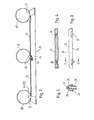
- Fig. 2 eine teilweise geschnittene Seitenansicht der in Fig. 1 dargestellten Anordnung, wobei die Druckwalze in drei verschiedenen Stellungen auf der Trägerplatte dargestellt ist,
- Fig. 3 eine Seitenansicht der Zentrierleiste,
- Fig. 4 eine Unteransicht der in Fig. 3 dargestellten Zentrierleiste,
- Fig. 5 einen Schnitt längs Linie V-V in Fig. 3,
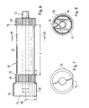
- Fig. 6 eine Seitenansicht der erfindungsgemäßen Druckwalze mit nur einem Handgriff,
- Fig. 7 eine Ansicht eines Handgriffes in axialer Richtung auf die der Druckwalze zugekehrte Fläche,
- Fig. 8 einen Schnitt durch die Druckwalze längs Linie VIII-VIII in Fig. 6,
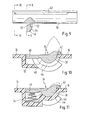
- Fig. 9 eine vergrößerte teilweise geschnittene Frontansicht einer Hälfte einer Klemmleiste,
- Fig. 10 einen Schnitt durch die Klemmleiste längs Linie X-X in Fig. 9, wobei die Klemmleiste in die Trägerplatte eingebaut ist,
- Fig. 11 einen der Fig. 10 entsprechenden Schnitt XI-XI in Fig. 9,
- Fig. 12 eine der Fig. 1 entsprechende Draufsicht auf eine zweite Ausführungsform der Erfindung und
- Fig. 13 einen Schnitt längs Linie XIII-XIII in Fig. 12.
- In Fig. 1 erkennt man eine allgemein mit 10 bezeichnete rechteckige Trägerplatte, die auf ihrer Oberseite entlang ihrer Längsränder jeweils eine Zahnstange 12 aufweist. Zwischen den Zahnstangen 12 sind in Form plattenförmiger Erhebungen mit höhengleichen Oberflächen eine rechteckige Druckplattenauflage 14 und eine ebenfalls rechteckige Druckträgerauflage 16 - in Längsrichtung der Zahnstangen 12 betrachtet - hintereinander angeordnet. Die Auflagen oder Tische 14 und 16 sind von den Zahnstangen 12 bzw. den Querrändern der Trägerplatte 10 jeweils durch vertiefte Bereiche 18 getrennt. Die Trägerplatte 10, die Zahnstangen 12, die Druckplattenauflage 14 und die Druckträgerauflage 16 sind als Kunststoffspritzgußteil einstückig miteinander gefertigt.
- An dem in der Fig. 1 linken Ende der Druckplattenauflage 14 wird die auf dieser liegende Druckplatte 20 mittels einerquer zu den Zahnstangen 12 gerichteten Zentrierleiste .22 gehalten, die näher in den Fig. 3 bis 5 dargestellt ist. Die Zentrierleiste besteht aus einem hohlen oder auch ausgefüllten Kunststoffteil, das gemäß Fig. 5 einen annähernd dreieckförmigen Querschnitt mit einer ebenen Basisfläche 24 und konvex gekrümmten Seitenflächen oder Flanken 26 aufweist. Der Scheitel zwischen den beiden konvex gekrümmten Seitenflächen 26 kann, wie in Fig. 5 dargestellt, geringfügig abgeflacht sein. An ihrer Basisfläche 24 trägt die Zentrierleiste 22 zwei Zapfen 28, die zum Eingriff in nicht dargestellte komplementäre Bohrungen 30 am linken Rand der Druckplattenauflage 14 bestimmt sind. Der Durchmesser und der Abstand der Zapfen 28 sind so gewählt, daß sie den entsprechenden Abmessungen eines üblichen Büro-Lochers entsprechen. Dadurch ist es möglich, die Druckplatte 20 mit einem derartigen Locher zu lochen und mit Hilfe der Zentrierleiste 22 und den Zapfen 28 nicht nur unverrückbar sondern auch in einer bestimmten Ausrichtung relativ zur Druckplattenauflage 14 auf dieserfestzuhalten. DieseLochung kann bei der Vorbereitung eines Satzes von Druckplatten für einen Mehrfarbendruck auch dazu verwendet werden, die Deckungsgleichheit des Motives auf den Druckplatten zu erreichen, so daß diese nach dem Aufspannen auf die Druckplattenauflage 14 exakt übereinander liegende Druckbilder ergeben.
- In einer Vertiefung 32 zwischen Druckplattenauflage 14 und Druckträgerauflage 16 ist eine Klemmleiste 34 angeordnet, die in den Fig. 9 bis 11 näher dargestellt ist und dazu dient, den Druckträger 36, in den meisten Fällen ein Stück Papier, auf der Druckträgerauflage 16 festzuhalten.
- Die Klemmleiste 34 besteht aus einem annähernd halbzylindrischen Mittelabschnitt 38, der entlang seinem einen Längsrand mit einer Betätigungsleiste 40 und entlang seinem anderen Längsrand mit einer Klaue 42 verbunden ist. Die Klemmleiste 34 ist mit ihrem Mittelabschnitt 38 in einer kreisbogenförmig gekrümmten Mulde 44 der Vertiefung 32 zwischen Druckplattenauflage 14 und Druckträgerauflage 16 gelagert, so daß sie durch Niederdrücken der Betätigungsleiste 40 um die Halbzylinderachse zwischen einer in Fig. 11 durch ausgezogene Linien dargestellten Klemmstellung und einer durch gestrichelte Linien wiedergegebenen Freigabestellung verschwenkbar ist.
- Die Klemmleiste 34 wird an der Trägerplatte 10 mittels kreissektorförmigerFlansche 46 gehalten (Fig. 9) die von dem halbzylindrischen Mittelabschnitt 38 abstehen und in im Bereich der Vertiefung 32 in der Trägerplatte 10 ausgebildete Schlitze (48) in derselben einsteckbar sind. Die Flansche 46 weisen auf ihrer jeweiligen Außenseite eine kreisbogenförmige Nut 50 auf, in welche ein kreisbogenförmig gekrümmter Schlitzrand 52 eingreift, wie dies in Fig. 9 durch gestrichtelte Linien angedeutet ist. Der kreisbogenförmig gekrümmte Schlitzrand 52 entsteht dabei durch den die Mulde 44 durchsetzenden Schlitz 48. Der Schlitz 48 ist dabei etwas schmaler als der jeweilige mit einer Einweisungsfläche 54 versehene Flansch 46, so daß diese unter Ausnutzung der zumindest geringfügigen Elastizität des für die Herstellung der Trägerplatte verwendeten Kunststoffmaterials in den Schlitz 48 eindrückbar ist, wobei der Schlitzrand 52 nach dem vollständigen Eindrücken des Flansches 46 in die flache kreisbogenförmige Nut 50 einrastet. Damit ist die Klemmleiste 34 schwenkbar aber sicher an der Trägerplatte 10 gehalten. Um die Klemmleiste 34 in ihre Klemmstellung vorzuspannen, ist zwischen dem Boden der Vertiefung 32 und der Betätigungsleiste 40 mindestens eine Schraubendruckfeder 56 angeordnet, wie dies in Fig. 11 zu sehen ist.
- Die Klemmleiste 34 hat neben ihrer Klemmfunktion noch die Funktion eines Richtanschlages, der die Lage des Druckträgers 36 in Längsrichtung der Zahnstangen 12 auf der Druckträgerauflage 16 festlegt. Um den Druckträger 36 auch quer zur Längsrichtung der Zahnstangen 12 auszurichten, ist an zumindest einer Seite der Druckträgerauflage 16 eine flache Erhebung 58 ausgebildet (Fig. 1) gegen die der Druckträger 36 anlegbar ist.
- Die Fig. 6 bis 8 zeigen die algemein mit 60 bezeichnete Druckwalze. Sie umfaßt einen zylindrischen Walzenkörper 62, der aus zwei Kunststoffhalbschalen besteht, die durch Schrauben oder andere Weise miteinander verbunden sind (Fig. 8). Der Walzenkörper 62 weist eine achsparallel gerichtete, zu seiner Umfangsfläche hin offene Zentriernut 64, deren Querschnittsprofil zumindest annähernd komplementär zu dem Querschnittsprofil der Zentrierleiste 22 ist. Der Walzenkörper 62 ist mit einem Gummituch 66 bespannt, das sich von einem Nutrand über den Umfang des Walzenkörpers 62 bis zum anderen Rand der Nut 64 erstreckt. Das Gummituch 66 kann auf eine beliebige Weise auf dem Walzenkörper befestigt werden. Dabei einigermaßen sorgfältiger Pflege des Gummituches dieses für sehr viele Druckvorgänge verwendet werden kann, kann es beispielsweise auf den Walzenkörper 62 aufgeklebt werden.
- An den axialen Enden weist der Walzenkörper jeweils einen Zahnkranz 68 auf, der auf seiner Innenseite durch einen radial überstehenden Führungsflansch 70 begrenzt wird. Der Kopfkreisdurchmesser des Zahnkranzes 68 ist geringfügig größer als der Durchmesser des mit dem Gummituch 66 bespannten Walzenkörpers 62. Der Zweck dieser Maßnahme wurde bereits eingangs erläutert. Die Zahnteilung der Zahnkränze 68 entspricht der Zahnteilung der Zahnstangen 12, wobei ein möglichst spielfreier Eingriff zwischen den Zahnkränzen 68 und den Zahnstangen 12 gewährleistet sein soll.
- Der axiale Abstand a zwischen den nach außen weisenden Stirnflächen der Führungsflansche 70 ist gleich dem Abstand b der einander zugekehrten Ränder der Zahnstangen 12, so daß die Druckwalze beim Aufliegen auf den Zahnstangen 12 in axialer Richtung praktisch spielfrei gehalten ist.
- Der Walzenkörper 62 wird von einer Walzenwelle 72 durchsetzt, die beispielsweise von einem Rohr gebildet sein kann. Die Walzenwelle 72 ragt in axialer Richtung jeweils über den Walzenkörper 62 hinaus und in eine entsprechende Bohrung 74 eines zylindrischen Handgriffes 76 hinein (Fig. 6). Der Handgriff 76 kann auf der Welle 72 mit beliebigen Mitteln befestigt werden, wobei selbstverständlich auch die Welle 72 starr mit dem Walzenkörper 62 verbunden und in den Handgriffen 76 drehbar gelagert sein könnte. Letztgenannte Ausführungsform ist jedoch komplizierter. Wie man in Fig. 6 erkennt, ist der Durchmesser der Handgriffe 76 größer als der Durchmesser der Führungsflansche 70. Gemäß Fig. 7 weisen die Handgriffe 76 ferner eine achsparallele ebene Fläche 78 auf, so daß die Druckwalze 60 nach dem Ablegen auf einer Unterlage nicht davon rollen kann. Der radiale Abstand c der Fläche 78 von der Wellenachse 80 ist dabei zumindest geringfügig größer als der Radius r-des Führungsflansches 70, so daß auch nach dem Ablegen der Walze 60 auf einer Unterlage der Walzenkörper 62 gedreht werden kann. Dies erleichtert beispielsweise das Säubern des Gummituches.
- Für einen Druck, beispielsweise einen Mehrfarbendruck werden in an sich bekannter Weise Druckplatten für die verschiedenen Farbstufen vorbereitet, wobei darauf zu achten ist, daß die auf den einzelnen Druckplatten festgehaltenen Teile der Druckvorlage exakt miteinander fluchten, wenn auch die Lochungen für die Zapfen 28 in den Druckplatten miteinander fluchten.
- Dann wird die erste Druckplatte mittels der Zentrierleiste 22 auf der Druckplattenauflage 14 ausgerichtet und festgeklemmt. Um eine Klemmwirkung zu erreichen, können die Zapfen 28 gegebenenfalls mit einem Umfangswulst oder einer geringfügigen Verdickung versehen sein, so daß sie in den betreffenden Bohrungen 30 in der Druckplattenvorlage 14 klemmen.
- Anliegend wird ein Druckträger;beispielsweise ein Stück Papier oder eine Karte o.dgl. auf der Druckträgerauflage 16 mittels des Anschlages 58 und der Klemmleiste 34 ausgerichtet und von der Klemmleiste 34 festgehalten. Dann wird die Druckwalze 60 an dem in der Fig. 2 linken Ende der Trägerplatte 10 so auf die Zahnstangen 12 gesetzt, daß die Zentrierleiste 28 in die Nut 64 in dem Walzenkörper 62 eingreift. Nach dem Einfärben der Druckplatte 20 wird die Druckwalze 60 mit einem angemessenen Druck über die Druckplatte 20 gerollt, wobei das Gummituch 66 von den eingefärbten Bereichen der Druckplatte 20 Farbe aufnimmt, so daß auf der Oberfläche des Gummituches 66 ein NegativBild der Druckplatte entsteht. Die Abmessungen der Anordnung sind so gewählt, daß der Walzenkörper 72 nach einmaliger Umdrehung mit der Nut 64 über der Klemmleiste 34 liegt, wie dies durch die mittlere Stellung der Druckwalze 60 in Fig. 2 angedeutet ist. Damit wird eine Behinderung der Druckwalzenbewegung durch die Klemmleiste 34 vermieden. Beim Weiterrollen der Druckwalze 60 in die in der Fig. 2 dargestellte rechte Endstellung wird dann das auf dem Gummituch 66 befindliche Bild auf den Druckträger 36 übertragen. Mit Erreichen des Zahnstangenendes wird durch eine Verringerung der Zahntiefe der Zahnstangen 12 die Druckwalze 60 von der Druckplatten- und Druckträgerebene abgehoben (siehe Fig. 2). Die Walze wird von der Trägerplatte 10 abgenommen und wieder auf die Zentrierleiste 22 gesezt. Es hat sich gezeigt, daß mit dieser Vorrichtung auch beim mehrmaligen Durchlauf der Druckwalze ein absolut scharfes Druckbild erreicht wird.
- In der Regel wird man zunächst eine der gewünschten Auflage entsprechende Anzahl von Druckträgern 36 mit einer Farbe bedrucken. Anschließend wird die Druckplatte gegen eine. anders eingefärbte Druckplatte ausgetauscht. Dann werden die bereits mit einer Farbe bedruckten Druckträger der Reihe nach mit der zweiten Farbe bedruckt u.s.w.. Trotz des einfachen Aufbaues und der einfachen Handhabung der erfindungsgemäßen Druckvorrichtung lassen sich einwandfreie scharfliniege Mehrfarbendrucke mit dieser Vorrichtung herstellen.
- Bei der in den Fig. 12 und 13 dargestellten zweiten Ausführungsform der Erfindung sind gleiche Teile wiederum mit gleichen Bezugszeichen versehen. Die in diesen Figuren dargestellte Ausführungsform unterscheidet sich von der anhand der Fig. 1 bis 11 beschriebenen ersten Ausführungsform lediglich dadurch, daß die Druckplattenauflage 14' und die Druckträgerauflage 16' als von der Trägerplatte 10 abnehmbare flache Platten ausgebildet sind, wie dies in Fig. 13 gut zu erkennen ist. Die Position der beiden Platten 14' und 16' auf der Trägerplatte 10 wird durch an dieser ausgebildete Zapfen 82 bestimmt, die in komplementär geformte Kerben 84 an den Rändern der Platten 14' und 16' eingreifen, wenn diese auf der Trägerplatte 10 liegen. Die Zapfen 82 ragen dabei nicht über die Oberfläche der Platten 14' und 16' hinaus. Der Vorzug dieser Anordnung besteht darin, daß dadurch über das Offsetdrucken hinaus noch andere Drucktechniken möglich sind. So kann anstelle der Druckplattenauflage 14' beispielsweise ein Linolschnitt, der wie andere Hoch-, Flach- und Tiefdruckformen seitenrichtig erstellt werden kann, auf die Trägerplatte 10 aufgelegt werden. Das Druckergebnis ist durch die indirekte Druckbildabnahme seitenrichtig. Ferner können nach dem Abnehmen der Druckträgerauflage 16' auch dickere Druckträger als das sonst übliche Papier aufgelegt werden. Die in den Fig. 12 und 13 dargestellte Ausführungsform ist aus den vorstehend beschriebenen Gründen vielseitiger verwendbar als die erste Ausführungsform, wobei jedoch gleichzeitig die für das Offsetdrucken und einen Mehrfarbendruck erforderliche Präzision erhalten bleibt.
Claims (16)
Applications Claiming Priority (4)
| Application Number | Priority Date | Filing Date | Title |
|---|---|---|---|
| DE3407044 | 1984-02-27 | ||
| DE3407044 | 1984-02-27 | ||
| DE3437035 | 1984-10-09 | ||
| DE19843437035 DE3437035A1 (de) | 1984-02-27 | 1984-10-09 | Offsetdruckeinrichtung |
Publications (2)
| Publication Number | Publication Date |
|---|---|
| EP0153733A2 true EP0153733A2 (de) | 1985-09-04 |
| EP0153733A3 EP0153733A3 (de) | 1986-04-16 |
Family
ID=25818860
Family Applications (1)
| Application Number | Title | Priority Date | Filing Date |
|---|---|---|---|
| EP85102104A Withdrawn EP0153733A3 (de) | 1984-02-27 | 1985-02-26 | Offsetdruckeinrichtung |
Country Status (3)
| Country | Link |
|---|---|
| US (1) | US4602563A (de) |
| EP (1) | EP0153733A3 (de) |
| DE (1) | DE3437035A1 (de) |
Families Citing this family (1)
| Publication number | Priority date | Publication date | Assignee | Title |
|---|---|---|---|---|
| US5367953A (en) * | 1992-07-01 | 1994-11-29 | Nsk Ltd. | Roller offset printing apparatus |
Family Cites Families (11)
| Publication number | Priority date | Publication date | Assignee | Title |
|---|---|---|---|---|
| US783188A (en) * | 1904-09-02 | 1905-02-21 | Fuchs & Lang Mfg Company | Transfer-cylinder hand-press. |
| US936954A (en) * | 1909-01-20 | 1909-10-12 | William L Sloane | Transfer-press. |
| GB191124798A (en) * | 1911-11-07 | 1912-05-09 | Alfred Julius Boult | Improvements in or relating to Offset Printing Presses. |
| FR601117A (fr) * | 1924-07-29 | 1926-02-23 | George Mann And Company Ltd So | Perfectionnements dans les machines à imprimer |
| US1866910A (en) * | 1929-03-14 | 1932-07-12 | Gugler Lithocraphic Company | Offset proof press |
| US1814806A (en) * | 1929-09-19 | 1931-07-14 | Charles Wagner | Imprint-transfer mechanism |
| US2147653A (en) * | 1936-04-17 | 1939-02-21 | Oxford Varnish Corp | Decorating apparatus |
| US3101050A (en) * | 1960-11-22 | 1963-08-20 | Reynolds Metals Co | Flat plate printing apparatus having accurate register |
| US3253541A (en) * | 1963-09-12 | 1966-05-31 | Signpress Company | Card printing machine |
| US3532053A (en) * | 1967-05-29 | 1970-10-06 | Jay Benjamin Lieberman | Printing press for dry-offset printing |
| US3633505A (en) * | 1969-10-13 | 1972-01-11 | David P Rankine | Image transfer printing machine |
-
1984
- 1984-10-09 DE DE19843437035 patent/DE3437035A1/de not_active Withdrawn
-
1985
- 1985-02-26 EP EP85102104A patent/EP0153733A3/de not_active Withdrawn
- 1985-02-27 US US06/706,145 patent/US4602563A/en not_active Expired - Fee Related
Also Published As
| Publication number | Publication date |
|---|---|
| US4602563A (en) | 1986-07-29 |
| EP0153733A3 (de) | 1986-04-16 |
| DE3437035A1 (de) | 1985-09-05 |
Similar Documents
| Publication | Publication Date | Title |
|---|---|---|
| DE3301933C2 (de) | Vorrichtung zum Farbbandhub und -transport in Schreib- und ähnlichen Maschinen | |
| DE2265611C2 (de) | Vorrichtung zum wählbaren Einstellen mehrerer Typenträger eines Stempels in einem Etikettenausgeber | |
| DE69405824T2 (de) | Farbwerk für Druckmaschinen | |
| DE3338450C1 (de) | Einrichtung zum Einfuehren der Endabschnitte eines flexiblen Aufzuges in eine Grube eines Zylinders einer Druckmaschine | |
| DE2552837A1 (de) | Druckvorrichtung | |
| DE2636387C2 (de) | Vorrichtung zum Transportieren von beidseitig gelochtem Papier in Druckgeräten, insbesondere bei Fernschreibmaschinen | |
| DE69013609T2 (de) | Vorrichtung zum automatischen Stempeln. | |
| EP0153733A2 (de) | Offsetdruckeinrichtung | |
| DE2547481B2 (de) | Vorrichtung zum Befestigen und Spannen von biegsamen Druckplatten | |
| DE1524549B1 (de) | Druckendes registriergeraet fuer messwerte | |
| DE3213540C2 (de) | Rotations-Druckmaschine für den Druck mit hoch viskosen Farben | |
| DE8405950U1 (de) | Offsetdruckeinrichtung | |
| DE408421C (de) | Vorrichtung an Druckereimaschinen zum Andruecken des Farblineals an die Farbkastenwalze | |
| EP0205971A2 (de) | Typenträgersatz für ein Stempeldruckwerk und Verfahren zum Zusammenbauen eines Stempeldruckwerks unter Verwendung eines solchen Typenträgersatzes | |
| DE2256952C2 (de) | Vorrichtung zum Aufkleben von Flexodruckplatten auf Druckzylinder | |
| DE898002C (de) | Zetteldrucker | |
| DE318702C (de) | ||
| DE2635006A1 (de) | Vorrichtung zur automatischen abstandsregelung zwischen einem druckkopf und einem zu bedruckenden informationstraeger | |
| DE2656422C2 (de) | Einfärbeinrichtung für ein Etikettiergerät | |
| DE2549004A1 (de) | Druckeinrichtung fuer schriftstuecke | |
| DE2850711C2 (de) | Einrichtung zum Verhindern des Verhakens des Farbbandes | |
| AT520868B1 (de) | Wiegestempel | |
| DE2621294A1 (de) | Druckkopf | |
| DE258705C (de) | ||
| DE2428745A1 (de) | Druckgeraet |
Legal Events
| Date | Code | Title | Description |
|---|---|---|---|
| PUAI | Public reference made under article 153(3) epc to a published international application that has entered the european phase |
Free format text: ORIGINAL CODE: 0009012 |
|
| AK | Designated contracting states |
Designated state(s): AT BE CH DE FR GB IT LI LU NL SE |
|
| PUAL | Search report despatched |
Free format text: ORIGINAL CODE: 0009013 |
|
| AK | Designated contracting states |
Kind code of ref document: A3 Designated state(s): AT BE CH DE FR GB IT LI LU NL SE |
|
| 17P | Request for examination filed |
Effective date: 19860919 |
|
| 17Q | First examination report despatched |
Effective date: 19880315 |
|
| STAA | Information on the status of an ep patent application or granted ep patent |
Free format text: STATUS: THE APPLICATION IS DEEMED TO BE WITHDRAWN |
|
| 18D | Application deemed to be withdrawn |
Effective date: 19880927 |
|
| RIN1 | Information on inventor provided before grant (corrected) |
Inventor name: SOINI, ROLAND |