EP0153660A2 - Concrete form element for the construction in permanent form - Google Patents
Concrete form element for the construction in permanent form Download PDFInfo
- Publication number
- EP0153660A2 EP0153660A2 EP85101553A EP85101553A EP0153660A2 EP 0153660 A2 EP0153660 A2 EP 0153660A2 EP 85101553 A EP85101553 A EP 85101553A EP 85101553 A EP85101553 A EP 85101553A EP 0153660 A2 EP0153660 A2 EP 0153660A2
- Authority
- EP
- European Patent Office
- Prior art keywords
- element according
- formwork element
- side walls
- connecting webs
- formwork
- Prior art date
- Legal status (The legal status is an assumption and is not a legal conclusion. Google has not performed a legal analysis and makes no representation as to the accuracy of the status listed.)
- Granted
Links
- 239000004567 concrete Substances 0.000 title claims abstract description 34
- 238000010276 construction Methods 0.000 title claims description 9
- 238000009415 formwork Methods 0.000 claims abstract description 101
- 238000009413 insulation Methods 0.000 claims abstract description 23
- 239000000853 adhesive Substances 0.000 claims description 22
- 230000001070 adhesive effect Effects 0.000 claims description 22
- 239000006260 foam Substances 0.000 claims description 22
- 210000002105 tongue Anatomy 0.000 claims description 14
- 230000000295 complement effect Effects 0.000 claims description 10
- 238000010438 heat treatment Methods 0.000 claims description 9
- 238000004519 manufacturing process Methods 0.000 claims description 7
- 238000013461 design Methods 0.000 claims description 6
- 239000002904 solvent Substances 0.000 claims description 6
- 210000002421 cell wall Anatomy 0.000 claims description 5
- 238000010790 dilution Methods 0.000 claims description 4
- 239000012895 dilution Substances 0.000 claims description 4
- 239000000945 filler Substances 0.000 claims description 4
- 230000003014 reinforcing effect Effects 0.000 claims description 4
- 230000007704 transition Effects 0.000 claims description 3
- 238000004026 adhesive bonding Methods 0.000 abstract description 5
- 239000004793 Polystyrene Substances 0.000 description 8
- 229920002223 polystyrene Polymers 0.000 description 8
- 238000011161 development Methods 0.000 description 7
- 230000000694 effects Effects 0.000 description 6
- 239000000463 material Substances 0.000 description 5
- 239000002184 metal Substances 0.000 description 5
- 238000003860 storage Methods 0.000 description 4
- 230000015556 catabolic process Effects 0.000 description 3
- 239000003292 glue Substances 0.000 description 3
- 230000035515 penetration Effects 0.000 description 3
- 230000003313 weakening effect Effects 0.000 description 3
- 238000004873 anchoring Methods 0.000 description 2
- 230000008901 benefit Effects 0.000 description 2
- 230000009172 bursting Effects 0.000 description 2
- 239000003063 flame retardant Substances 0.000 description 2
- 230000035939 shock Effects 0.000 description 2
- XLYOFNOQVPJJNP-UHFFFAOYSA-N water Substances O XLYOFNOQVPJJNP-UHFFFAOYSA-N 0.000 description 2
- 239000004925 Acrylic resin Substances 0.000 description 1
- 229920000178 Acrylic resin Polymers 0.000 description 1
- 239000010754 BS 2869 Class F Substances 0.000 description 1
- 229920006328 Styrofoam Polymers 0.000 description 1
- 239000000443 aerosol Substances 0.000 description 1
- 238000013459 approach Methods 0.000 description 1
- 230000015572 biosynthetic process Effects 0.000 description 1
- 230000001680 brushing effect Effects 0.000 description 1
- 238000005266 casting Methods 0.000 description 1
- 239000001913 cellulose Substances 0.000 description 1
- 229920002678 cellulose Polymers 0.000 description 1
- 238000005253 cladding Methods 0.000 description 1
- 239000002131 composite material Substances 0.000 description 1
- 238000001514 detection method Methods 0.000 description 1
- 238000009826 distribution Methods 0.000 description 1
- 238000007667 floating Methods 0.000 description 1
- 239000011381 foam concrete Substances 0.000 description 1
- 238000009499 grossing Methods 0.000 description 1
- 239000010440 gypsum Substances 0.000 description 1
- 229910052602 gypsum Inorganic materials 0.000 description 1
- 229910052500 inorganic mineral Inorganic materials 0.000 description 1
- 238000003780 insertion Methods 0.000 description 1
- 230000037431 insertion Effects 0.000 description 1
- 239000011810 insulating material Substances 0.000 description 1
- 238000002955 isolation Methods 0.000 description 1
- 238000005304 joining Methods 0.000 description 1
- 238000000034 method Methods 0.000 description 1
- 239000011707 mineral Substances 0.000 description 1
- 230000004048 modification Effects 0.000 description 1
- 238000012986 modification Methods 0.000 description 1
- 239000004570 mortar (masonry) Substances 0.000 description 1
- 238000005192 partition Methods 0.000 description 1
- 230000000149 penetrating effect Effects 0.000 description 1
- 239000011505 plaster Substances 0.000 description 1
- 239000013502 plastic waste Substances 0.000 description 1
- 229920001225 polyester resin Polymers 0.000 description 1
- 239000004645 polyester resin Substances 0.000 description 1
- 230000008569 process Effects 0.000 description 1
- 230000009467 reduction Effects 0.000 description 1
- 239000011150 reinforced concrete Substances 0.000 description 1
- 238000007711 solidification Methods 0.000 description 1
- 230000008023 solidification Effects 0.000 description 1
- 238000005507 spraying Methods 0.000 description 1
- 239000008261 styrofoam Substances 0.000 description 1
- 239000002344 surface layer Substances 0.000 description 1
- 239000000725 suspension Substances 0.000 description 1
- 238000009423 ventilation Methods 0.000 description 1
- 229910052902 vermiculite Inorganic materials 0.000 description 1
- 239000010455 vermiculite Substances 0.000 description 1
- 235000019354 vermiculite Nutrition 0.000 description 1
- 238000003466 welding Methods 0.000 description 1
Images


Classifications
-
- E—FIXED CONSTRUCTIONS
- E04—BUILDING
- E04C—STRUCTURAL ELEMENTS; BUILDING MATERIALS
- E04C1/00—Building elements of block or other shape for the construction of parts of buildings
- E04C1/40—Building elements of block or other shape for the construction of parts of buildings built-up from parts of different materials, e.g. composed of layers of different materials or stones with filling material or with insulating inserts
-
- E—FIXED CONSTRUCTIONS
- E04—BUILDING
- E04B—GENERAL BUILDING CONSTRUCTIONS; WALLS, e.g. PARTITIONS; ROOFS; FLOORS; CEILINGS; INSULATION OR OTHER PROTECTION OF BUILDINGS
- E04B2/00—Walls, e.g. partitions, for buildings; Wall construction with regard to insulation; Connections specially adapted to walls
- E04B2/84—Walls made by casting, pouring, or tamping in situ
- E04B2/86—Walls made by casting, pouring, or tamping in situ made in permanent forms
- E04B2/8635—Walls made by casting, pouring, or tamping in situ made in permanent forms with ties attached to the inner faces of the forms
- E04B2/8641—Walls made by casting, pouring, or tamping in situ made in permanent forms with ties attached to the inner faces of the forms using dovetail-type connections
-
- E—FIXED CONSTRUCTIONS
- E04—BUILDING
- E04B—GENERAL BUILDING CONSTRUCTIONS; WALLS, e.g. PARTITIONS; ROOFS; FLOORS; CEILINGS; INSULATION OR OTHER PROTECTION OF BUILDINGS
- E04B2/00—Walls, e.g. partitions, for buildings; Wall construction with regard to insulation; Connections specially adapted to walls
- E04B2/02—Walls, e.g. partitions, for buildings; Wall construction with regard to insulation; Connections specially adapted to walls built-up from layers of building elements
- E04B2002/0202—Details of connections
- E04B2002/0232—Undercut connections, e.g. using undercut tongues and grooves
- E04B2002/0239—Round dovetails
-
- E—FIXED CONSTRUCTIONS
- E04—BUILDING
- E04B—GENERAL BUILDING CONSTRUCTIONS; WALLS, e.g. PARTITIONS; ROOFS; FLOORS; CEILINGS; INSULATION OR OTHER PROTECTION OF BUILDINGS
- E04B2/00—Walls, e.g. partitions, for buildings; Wall construction with regard to insulation; Connections specially adapted to walls
- E04B2/84—Walls made by casting, pouring, or tamping in situ
- E04B2/86—Walls made by casting, pouring, or tamping in situ made in permanent forms
- E04B2002/8676—Wall end details
Definitions
- the invention relates to a formwork element for the shell concrete construction, in particular made of rigid foam, with side walls, which are provided at their edges with grooves and springs for securing the position and can be connected by webs and, if appropriate, end walls.
- Known large-format formwork elements of this type can also be used in a variety of ways in composite structures and enable cost-effective and quick construction of buildings with good external and internal thermal insulation.
- improvements are desirable.
- the formwork elements should be stable and resistant to internal and external loads with regard to the often storey-high concrete backfill, and should enable cheap manufacture and space-saving transport.
- the invention is therefore based on the object to provide formwork elements for the sheath concrete construction, which can be used universally, can be produced cheaply with short cycle times, can withstand high loads, especially when filling with concrete, require little transport and storage space and can also be used as insulation boards for Allow many uses.
- the invention is based on a formwork element of the type mentioned at the outset and is characterized in that the side walls are provided on their inside with snap-in points at which the webs can be fixed in position.
- a material of high strength and heat resistance can be selected for the connecting webs, for example reinforced concrete, so that the side walls withstand a high internal pressure when filling the concrete.
- connecting webs made of hard foam for example, in the case of one-piece production of the formwork elements, the penetration of a fire is avoided.
- the storage and transport costs remain low because the individual parts first have to be assembled at the construction site or in a regional interim storage facility. This is in contrast to also known formwork elements (US Pat. No. 4,223,501), in which connecting webs in the form of metal grids or sheets are inserted into the mold during manufacture.
- the material of the connecting bridges can also be chosen so that the dreaded acoustic bridges are avoided and the clairaudience of the buildings can be eliminated.
- the snap-in points are formed by a shallow depression with undercut edges, into which an adapted counterpart can be inserted in a latching manner.
- the locking points can also be replaced by a shallow elevation with indented edges are formed, on which an adapted counterpart can be latched.
- a snap-in or clip connection is then created between the side wall on the one hand and the connecting elements or other parts on the other hand, which pulls the two parts against one another.
- an adhesive can be applied or sprayed on before snapping into place.
- the depression or the elevation can be relatively flat, for example a height or depth of 2 to 5 mm, so that there is practically no weakening of the side walls.
- the shape of the depression or elevation and the corresponding counterpart can be chosen depending on the circumstances. However, a circular shape is particularly useful. But there is also the possibility of forming the recesses as a tongue or groove with a dovetail cross section. One or more grooves or tongues can run through to the upper edge and / or to the lower edge of the side walls, so that the corresponding counterpart can be inserted. The remaining parts of the grooves or tongues lead to an additional anchoring of the side walls on the concrete without additional measures. The attachment is also ensured if the glued joints between the side walls and the connecting webs no longer hold. For the correct positioning of the connecting webs or other counterparts, the groove or the tongue can be provided with centering points.
- the locking points are formed by a ball socket or a ball for locking a ball or a ball socket.
- the ball or the ball socket can be arranged on an elevation or at the bottom of a depression, which expediently has a circular shape.
- the connecting webs each have a contact surface at both ends, which are designed as a counterpart to the elevation or depression and / or the ball or ball socket, there is the possibility of contacting one another Additional surfaces to be glued together over a large area.
- the ball and the ball socket should be designed so that a certain amount of tension remains after the assembly, which ensures secure contact and a good glue point.
- the contact surfaces may be used for other V ER- enlargement of the adhesive surface be provided with extending beyond the elevation or depression extensions.
- the latching points can also be formed by grooves arranged at the same distance from one another, running from top to bottom and distributed over the entire inner surface of the side walls.
- the cross section of the grooves can be rectangular or so designed that the grooves are widened at their base, that is to say, for example, in the form of a dovetail.
- Formwork elements designed in this way can be manufactured with practically any desired length or cut to the required size, as required.
- the grooves improve the adhesion of the side walls to the concrete, so that the penetration of water into the gap between the side wall and the concrete is prevented and, moreover, no tones can arise when the side wall strikes the solidified concrete.
- the recess in the grooves creates webs between two adjacent grooves, the cross-section of which can advantageously be complementary to the cross-section of the grooves.
- the tongue and groove surface of the side walls has a shock-absorbing effect when pouring the concrete, which often falls from a relatively high height. Individual chunks are then spring-loaded and do not lead to the formwork elements being destroyed by bursting.
- the side walls are preferably made of rigid foam. However, other materials can also be used. In particular, it is possible to connect side walls of different types to one another. For example, a hard foam side wall can be used on the outside of a building and a gypsum fibreboard can be used on the inside. Other combinations, also with mineral insulating materials, are possible.
- the material of the connecting webs is appropriately chosen so that a good connection is achieved and there is no risk of fire breakdown.
- a further development of the invention recommends that the connecting webs consist of concrete at least in the area of their contact surfaces. Lightweight concrete (vermiculite) is also suitable here.
- the connecting webs can have one or more reinforcing bars in the central area, which are either exposed or already cast with concrete.
- the connecting webs made of concrete can also expediently have coaxial bores from both ends which end at a short distance from one another. The remaining concrete residue between the two holes prevents fire penetration, but on the other hand can easily be pierced later, for example for convenient attachment of fastening or support parts as well as for the passage of lines and pipes. Finding the right place is particularly easy when the side walls have centering points on their outside. which marks the position of the connecting webs and, if applicable, their bores.
- Connecting webs made in one piece from concrete have plate-shaped end plates on both sides, which are connected via a central shaft.
- the plate-shaped end plates suitably have a circular shape, but can also be oval, rectangular or any other shape.
- the shaft can have at least one circumferential groove at the transition to the end plates. Reinforcing bars can be inserted correctly positioned in this groove. Two adjacent grooves allow such bars to cross.
- the contact surfaces of the connecting webs are expediently designed as a counterpart to the latching points on the side walls in order to achieve a good connection.
- the latching points are formed by grooves arranged at the same distance from one another, running from top to bottom and distributed over the entire inner surface of the side walls, the contact surfaces on the end plates of the connecting webs have an adapted shape with alternating grooves and tongues. Even if the grooves in the side walls are undercut, the corresponding tongues of the end plates can have a rectangular or square cross-section so that they can be easily inserted. A high degree of strength is achieved through large-area gluing. Because of the continuous grooves on the side walls, the connecting webs can be attached at the desired height and at any point. If the end plates are attached in such a way that they bridge the vertical or horizontal gap between formwork elements, they also serve to connect adjacent elements. Several formwork elements can be connected at the joint between a horizontal and a vertical gap.
- the connecting webs can also be realized in the form of two plates forming the contact surfaces, which are connected via preferably crossed tension struts in the form of wires or flat elements. It is important to achieve a certain spring effect, which helps to avoid sudden loading of the side walls when pouring concrete and thus avoid tearing out the connecting webs from the side walls.
- the side walls in a further development of the invention can be provided on their inside with trough-shaped depressions or web-like elevations, preferably running parallel to the narrow sides of the side walls. Elevations are particularly suitable if the latching points of the side walls also have elevations, so that the thickness of the side walls and thus the storage and transport space used do not increase additionally. In the other case, ie if the snap-in points have depressions preferably also groove-shaped depressions.
- the side walls can be provided on their outside with a raised or recessed grid, which enables parts of the formwork elements to be cut to size on the construction site. A cross grid or a pattern of parallel vertical lines can be provided. The depth of the corresponding channels or the height of the corresponding webs only has to be so large that a correct detection is possible.
- the grooves and tongues provided on the edges of the side walls for securing the position are undercut according to a particularly advantageous development of the invention, so that a tensile connection between adjacent side walls is created.
- the springs can be dovetail-like with correspondingly adapted grooves, rounded edges being expedient. There is also the possibility that the springs in cross section have approximately the shape of a circle, which is connected to the side wall via a short extension.
- the grooves are complementary. Such a rounded design has the advantage that dirt caused by concrete residues can be removed more easily in rough operation on the construction site.
- the locking points can also be realized in that the side walls at the top and bottom edge have blind holes with a T-shaped cross section open to the inside for the latched reception of end plates of the connecting webs.
- the blind holes can be relatively close to the inner surface, so that there is no major weakening of the side walls.
- the depth of the blind holes can correspond to half the dimensions of the end plates Chen, so that the end plates are each arranged half in a formwork element and the other half in the formwork element above.
- the end plates expediently have a square shape and are connected by a rectangular bar. Then the connecting webs can be rotated alternately by 90 ° with each other, whereby a higher torsional rigidity is achieved.
- the cross section of the blind holes must then be adjusted accordingly.
- the end plates can be made of sheet metal, for example.
- the connecting rods can be welded wires.
- a further development provides that two connecting webs, each with two end plates, are connected to one another in the region of their connecting rods between the end plates. If the connection is made in the middle of the connecting rods, an X-shaped structure is created, which in turn has a certain spring effect. In addition, the distance between two double connecting webs of this type is increased in the middle of the respective wall, as a result of which pipes of larger cross-section (for example with a diameter of 100 mm) can be accommodated without difficulty.
- the formwork elements according to the invention can be adapted to all practical requirements with the help of only one type of side wall, associated connecting webs and only one end wall. So there is no need to use special corner elements and other connecting elements of different shapes.
- the side walls can be used as thermal insulation panels.
- Such insulation boards can be installed as roof insulation boards on or under the rafters.
- the positive connection enables fast and clean work.
- the panels can have a relatively long length of, for example, 2 m, because the formwork elements can also be large.
- the thermal insulation boards can be laid on floating screed and, if necessary, carry pipes or hoses for underfloor heating.
- the thermal insulation panels can also be attached to the outside or inside of buildings.
- the snap-in points are formed by grooves arranged at the same distance from one another, running from top to bottom and distributed over the entire inner surface of the side walls, in the case of roof insulation panels the grooves are arranged upwards and in the direction of the roof , so that penetrating or condensing water can run off to the eaves.
- the tongue and groove side is brought down to enable better impact sound insulation.
- the grooves also enable the side walls to be retrofitted as interior or exterior wall insulation when using plaster or adhesive mortar.
- holders can also be used which are designed as one end of the connecting stele, cooperate with the snap-in points of the thermal insulation panel in the form of the side wall and can be fixed on the wall.
- the right one Positioning of the holders are appropriately used templates.
- the holders advantageously have a contact surface with a ball on one foot, which snap into ball sockets on the side walls. If the heat insulation plate in the form of the side wall is used as an insulating plate for underfloor heating, holding devices for the pipes or hoses of the underfloor heating are expediently used, which are designed like one end of the connecting webs and interact with the latching points.
- the holding devices can have a ball which snaps into a ball socket of the side wall or heat insulation plate and which merges into a head provided with a bore for the hose or the pipe, the ball extending into the Has hole through slot.
- the holder can then be bent open in the area of the slot, placed over the pipe or hose and then snapped into the ball socket.
- a fire-retardant rigid foam of class F is used to eliminate the risk of fire.
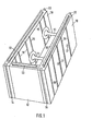
- FIG. 1 The embodiment of a formwork element according to the invention shown in perspective in FIG. 1 has two side walls 10 made of fire-retardant hard foam, which are connected to one another via two webs 11 and an end wall 12.
- the upper and lower edges as well as the front edges of the side walls 10 and the upper and lower edges of the end wall 12 are provided with webs 13 or complementary grooves 14 which are circular in cross section with a short approach are trained.
- To assemble the springs 13 are inserted into the grooves 14.
- Markings in the form of flat channels 16 are arranged on the outside of the side walls 10, which enable a cut to size. Centering points 17 mark the position of the connecting webs 11.
- FIG. 2 shows in more detail an embodiment for the latching point between the side wall 10 and a connecting web 11.
- the side wall has a flat recess 18 with an undercut edge
- the foot 19 of the connecting element 11 has a complementary elevation 20 with a retracted edge, which can be snapped or clipped into the recess 18 by snapping.
- the shape is such that a certain amount of tension remains after clipping in and thus the connecting web 11 is held securely against the wall 10. If you glue the surfaces that are next to each other with adhesive before clipping in, this results in a very secure and tensile connection.
- FIG 3 shows a complementary design of the connection point between the connecting web 11 and the side wall 10.
- the foot 19 contains the flat depression 18 and the wall 10 contains the corresponding elevation 20.
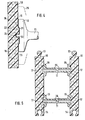
- FIG. 4 Another embodiment for the connection between the side wall 10 and the connecting element 11 is shown in FIG. 4.
- the foot 19 of the connecting web 11 has a flat, central recess 21, and the Wall 10 is equipped with a corresponding elevation 22.
- a ball 23 is arranged in the center of the depression 21 and engages in a ball socket 24 by being pressed into it.
- a residual tension is exerted on the connecting element 11 after it has snapped in, so that a secure fit and good adhesion is achieved.
- the foot 19 of the connecting web 11 can be provided with extensions 25 indicated by dashed lines.
- FIG. 5 shows a cross section through the formwork element according to FIG. 1.
- two connecting elements 11 arranged one above the other are connected to the side walls 10 by latching.
- the connecting elements 11 consist of concrete and have central bores 26 from both sides, which end at a distance of a few centimeters from one another.
- the centering points 17 on the outside of the side walls 10 mark the position of the bores 26, so that later it is possible to drill through the remaining residue between the two bores 26 for the passage of lines or cables or the attachment of fastening and supporting elements.
- a connecting element 31 which has two end plates 27 and connecting wires or rods 28.
- the plates 27 are snapped into a recess 18, similar to the embodiment according to FIG. 2, and additionally glued there.
- the wires 28 are easily welded to the plates 27 made of sheet metal. The crossing of the wires results in a certain suspension effect, which mitigates shocks when filling with concrete.
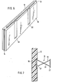
- the side wall 10 shown in perspective is provided with latching points in the form of blind holes 30 with a T-shaped cross section, which are arranged on the upper edge and lower edge.
- the relatively flat blind holes 30 do not significantly weaken the side wall but allow the snap-in connecting webs 41, which are shown in FIG. 9, in a simple manner.
- Each connecting web 41 has an end plate 32 of square shape and a connecting rod 33 with a rectangular cross section.
- the connecting webs 41 are used alternately in the position shown in FIGS. 9a and 9b, that is to say with a rotation of 90 °.
- the blind holes 30 must be adjusted accordingly (not shown) with regard to their connection to the inner surface of the side wall 10.
- FIG. 10 shows an exemplary embodiment of a double connecting web 51.
- Two cranked connecting wires 34 each have plates 35 at their ends, which can be designed similarly to the plates 32 in FIG. 9. The plates lie in the blind holes 30 according to FIG. 8.
- the wires 34 are connected to one another in accordance with the schematic illustration, for example by screwing or welding.
- a double connecting element 51 with an X-shape is created, which in turn has a certain spring effect and can thus absorb shocks.
- FIG. 12 shows, in the form of a partial section, the attachment of a side wall 10 used as a thermal insulation panel to a building wall 40 to be insulated.
- the ball socket 24 (cf. FIG. 4) of the panel 10 which in the exemplary embodiment shown does not rise directly in the wall 10 is attached, the ball 23 of a holder 42 engages, a flange 43 laying against the plate 10.
- gluing in the area of Flange 43 and the ball 23 take place.
- a foot 44 which contains a screw 45 with which the holder 42 is screwed into the wall 40 to be insulated, adjoins the flange 43 of the holder 42. The distance between the plate 10 and the wall 40 achieved by the holder 42 results in a desired additional insulation and ventilation.
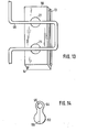
- FIG. 13 schematically shows the use of a side wall 10 as a floor insulation panel with a hose 46 of an underfloor heating.
- the hose 46 can be positioned exactly at the stop points, which are only shown schematically in the form of, for example, elevations 21 according to FIG. 4, wherein a fastening element according to FIG. 14 can be used.
- the fastening element has a ball 53 similar to the ball 23 in Figure 4.
- a head 54 with a bore 55 for receiving the hose 46 connects to the ball.
- a slot 56 leads through the ball to the bore 55, so that the two halves of the ball 53 can be bent and in this way the hose can be brought into the bore 55.
- the ball 53 is then pressed into a ball socket (not shown) corresponding to the ball socket 24 in FIG. 4.
- FIG. 6 A modification of the side wall 10 is shown in FIG. 6.
- dovetail grooves 58 are provided which start from the upper edge and end in front of the lower edge of the wall 10.
- connecting elements 11 with a correspondingly designed foot can be inserted and glued into the dovetail grooves 58.
- the remaining free parts of the dovetail groove 58 cause the side wall 10 to be additionally fixed to the filled concrete.
- the side walls 10 alternately have grooves 60 on their entire inside, which are at their base are expanded and thus have the shape of a rounded dovetail.
- the webs 61 between adjacent grooves 60 have a cross section that is complementary to the grooves 60.
- the associated connecting webs 11 are expediently made in one piece from concrete. They have plate-shaped end plates 62, the outer surfaces of which have webs 63 which penetrate into the grooves 60 and grooves 64 which receive the webs 61.
- the webs 63 which can be continuous or interrupted, have a rectangular cross section, so that the connecting webs 11 can be inserted into the side walls 10. This can be done practically anywhere and at any height of the formwork elements.
- a very high strength of the connection point between the connecting webs 11 and the side walls 10 can be achieved by using a suitable adhesive.
- An end piece 66 closes off the corner from the outside. 15 on the edges, this end piece has the same grooves 60 and tongues 61 as the side walls 10 and can therefore be pushed into the side walls while achieving a non-positive connection.
- Those facing the inside of the formwork element Grooves and tongues 60, 61 of the connecting piece 66 serve, like the free grooves 60, 61 of the side walls 10, of a resilient padding which dampens the dynamic forces which then occur when the concrete is poured in.
- FIG. 17 shows a T-shaped connection point between formwork elements according to FIG. 15. Again, no special designs are required. It is only necessary to remove part of the .side wall 10 at the joint at 67, so that there is again no risk of fire breakdown. The connecting webs 11 are brought close to the point 67 in order to achieve the required strength or project into this.
- FIG. 18 schematically shows a ceiling closure using formwork elements according to FIG. 15.
- the upper part of the side wall 10 is removed from the uppermost formwork element in accordance with the thickness of the ceiling 68 shown in broken lines at 69 up to the height of the filled-in concrete 70.
- the protruding part of the end plate 62 of the uppermost connecting web 11 can be knocked off, if necessary.
- the connecting web 11 has two circumferential grooves 71 on both sides at the transition into the end plates 62.
- Horizontal and / or vertical reinforcing bars 72 can be inserted into these in a positioned manner.
- an adhesive which contains a solvent for polystyrene in an appropriate dilution, the dilution being selected such that the cell walls of the polystyrene only are dissolved and softened so far that a smoothing of the surface of the polystyrene and adjustment to the surface of the webs is made possible without the cell walls of the polystyrene collapsing.
- This dissolving of the cell walls in the surface area of the rigid foam surprisingly leads to a solidification of the surface of the formwork element, since the rigid foam balls from which the rigid foam is made bake together, so that a welded surface layer of the rigid foam is produced in the area of the adhesive point.
- the adhesive used it is important to use the solvent of the rigid foam in a controlled manner. This generally requires dilution with a filler or the like based on cellulose, acrylic resin or polyester resin. can exist. This filler also has the function of filling any gaps between the formwork element and the webs.
- the consistency of the adhesive can be adapted to the application process, with spraying, brushing and filling.
- glue can be applied to either the web or the rigid foam or to these two parts.
- the adhesive applied to the webs can differ from the adhesive applied to the rigid foam, in particular it can be portions of a two-component adhesive. If both sides of the surfaces to be glued are treated with adhesive, then the consistency of the adhesives for one side, for example the webs, can differ from the consistency of the adhesives on the other side, that is, the rigid foam. For example, one side to be glued is sprayed with an aerosol, while the other side is coated with a paste, which ensures surface leveling between the surfaces to be glued.
- the S chalungssystem for the cladding concrete manner can be supplemented by a further not shown member, whereby in particular horizontal formwork end walls can be formed.
- This element has latching points on its narrow sides which correspond to the corresponding latching points 18, 20, 23, 27, 63, 64 of the webs and thus cooperate with the latching points 18, 20, 24, 30, 58, 60, 61 of the wall formwork elements can.
- These formwork elements provided to form a horizontal formwork end wall have a width which corresponds to the length of the webs, while the length of these elements is not critical and can be, for example, 1 m, since one can form a horizontal formwork end wall from individual pieces.
- these formwork elements expediently have tongue and groove on their small narrow sides, which can have the design according to parts 13, 14. In this way it is possible to put together a continuous, horizontal formwork end wall from individual formwork elements.
- Such a horizontal formwork wall is inserted into the vertically running snap-in points of the narrow sides of the side wall formwork elements 10 and held by
- the advantage is that the horizontal formwork end wall can be moved up or down as far as this corresponds to the height of the window opening or door opening. It is understood that the horizontal formwork end wall is supported in a known manner from below when casting the lintel.
Landscapes
- Engineering & Computer Science (AREA)
- Architecture (AREA)
- Civil Engineering (AREA)
- Structural Engineering (AREA)
- Physics & Mathematics (AREA)
- Electromagnetism (AREA)
- Forms Removed On Construction Sites Or Auxiliary Members Thereof (AREA)
- Building Environments (AREA)
- Moulds, Cores, Or Mandrels (AREA)
- Curtains And Furnishings For Windows Or Doors (AREA)
- Materials For Medical Uses (AREA)
Abstract
Es wird ein Schalungselement für die Mantelbetonweise mit Seitenwänden (10) beschrieben, die an ihren Kanten mit Nuten (14) und Federn (13) zur Lagesicherung versehen und durch Stege (11) und gegebenenfalls Endwände (12) verbunden sind. Die Seitenwände (10) besitzen auf ihrer Innenseite Einraststellen, an denen die Verbindungsstege (11) positioniert festlegbar sind. Die Einraststellen werden beispielsweise durch aneinander angepaßte, hinterschnittene Vertiefungen und Erhöhungen, Kugeln und Kugelpfannen oder auch flache Rastnuten gebildet. Eine Verklebung sorgt für die erforderliche Festigkeit. Die Seitenwände (10) lassen sich auch als Dämmplaten in Form von Dach- oder Fußbodendämmplaten sowie auch zur Wärmedämmung auf der Außen- und Innenseite von Gebäuden verwenden.A formwork element for the sheath-concrete manner with side walls (10) is described, which are provided at their edges with grooves (14) and springs (13) for securing the position and are connected by webs (11) and optionally end walls (12). The inside of the side walls (10) has snap-in points at which the connecting webs (11) can be positioned. The snap-in points are formed, for example, by mutually adapted, undercut depressions and elevations, balls and ball sockets or flat locking grooves. Gluing ensures the required strength. The side walls (10) can also be used as insulation boards in the form of roof or floor insulation boards and also for thermal insulation on the outside and inside of buildings.
Description
Die Erfindung betrifft ein Schalungselement für die Mantelbetonbauweise, insbesondere aus Hartschaumstoff, mit Seitenwänden, die an ihren Kanten mit Nuten und Federn zur Lagesicherung versehen sind und durch Stege und gegebenenfalls Endwände verbindbar sind.The invention relates to a formwork element for the shell concrete construction, in particular made of rigid foam, with side walls, which are provided at their edges with grooves and springs for securing the position and can be connected by webs and, if appropriate, end walls.
Bekannte großformatige Schalungselemente dieser Art (DE-AS 26 18 125) lassen sich vielseitig auch im Verbund einsetzen und ermöglichen ein kostensparendes und schnelles Erstellen von Bauwerken mit guter äußerer und innerer Wärmedämmung. Im Hinblick auf die vielseitigen Anforderungen an solche Schalungselemente sind jedoch Verbesserungen wünschenswert. Insbesondere sollen die Schalungselemente im Hinblick auf die häufig geschoßhohe Betonverfüllung stabil und widerstandsfähig gegen innere und äußere Belastungen sein, eine billige Herstellung und einen platzsparenden Transport ermöglichen. Der Erfindung liegt demgemäß die Aufgabe zugrunde, Schalungselemente für die Mantelbetonbauweise zu schaffen, die universal einsetzbar sind, sich billig bei kurzen Taktzeiten herstellen lassen, hohe Beanspruchungen insbesondere beim Verfüllen mit Beton aushalten, wenig Transport- und Lagerraum benötigen und auch eine Verwendung als Dämmplatten für vielerlei Einsatzzwecke zulassen.Known large-format formwork elements of this type (DE-AS 26 18 125) can also be used in a variety of ways in composite structures and enable cost-effective and quick construction of buildings with good external and internal thermal insulation. With regard to the diverse requirements for such formwork elements, however, improvements are desirable. In particular, the formwork elements should be stable and resistant to internal and external loads with regard to the often storey-high concrete backfill, and should enable cheap manufacture and space-saving transport. The invention is therefore based on the object to provide formwork elements for the sheath concrete construction, which can be used universally, can be produced cheaply with short cycle times, can withstand high loads, especially when filling with concrete, require little transport and storage space and can also be used as insulation boards for Allow many uses.
Zur Lösung der Aufgabe geht die Erfindung aus von einem Schalungselement der eingangs genannten Art und ist dadurch gekennzeichnet, daß die Seitenwände auf ihrer Innenseite mit Einraststellen versehen sind, an denen die Stege positioniert festlegbar sind.To achieve the object, the invention is based on a formwork element of the type mentioned at the outset and is characterized in that the side walls are provided on their inside with snap-in points at which the webs can be fixed in position.
Auf diese Weise besteht die Möglichkeit, die Seitenwände und die Verbindungsstege getrennt und aus unterschiedlichem Material herstellen zu können. Dadurch werden die Herstellungsformen einfacher und billiger und ermöglichen kurze Taktzeiten. Für die Verbindungsstege kann ein Material hoher Festigkeit und Hitzebeständigkeit gewählt werden, beispielsweise armierter Beton, so daß die Seitenwände bei der Betonverfüllung einen hohen inneren Druck aushalten. Im Gegensatz zu Verbindungsstegen aus beispielsweise Hartschaum bei einstückiger Herstellung der Schalungselemente wird das Durchschlagen eines Brandes vermieden. Der Lager- und Transportaufwand bleibt klein, weil die Einzelteile erst an der Baustelle oder auch in einem regionalen Zwischenlager zusammengesetzt werden müssen. Das steht im Gegensatz zu ebenfalls bekannten Schalungselementen (US-PS 4 223 501), bei denen Verbindungsstege in Form von Metallgittern oder Blechen schon während der Herstellung in die Form eingesetzt werden. Das ist schwierig und umständlich und führt außerdem zu Kältebrücken, weil die Metallteile zur sicheren Verankerung verhältnismäßig nahe an der Außenfläche enden. Das ebenfalls bekannte, nachträgliche Einschieben von Blech-Verbindungsstegen in vorgefertigte Schlitze oder Nuten ( US-PS 3 788 020) führt zu einer bedenklichen Schwächung der Seitenwände durch die Schlitze oder Nuten und läßt ebenfalls Kältebrücken entstehen.In this way, it is possible to be able to produce the side walls and the connecting webs separately and from different materials. This makes the manufacturing forms easier and cheaper and enables short cycle times. A material of high strength and heat resistance can be selected for the connecting webs, for example reinforced concrete, so that the side walls withstand a high internal pressure when filling the concrete. In contrast to connecting webs made of hard foam, for example, in the case of one-piece production of the formwork elements, the penetration of a fire is avoided. The storage and transport costs remain low because the individual parts first have to be assembled at the construction site or in a regional interim storage facility. This is in contrast to also known formwork elements (US Pat. No. 4,223,501), in which connecting webs in the form of metal grids or sheets are inserted into the mold during manufacture. This is difficult and cumbersome and also leads to cold bridges, because the metal parts end relatively close to the outer surface for secure anchoring. The also known, subsequent insertion of sheet metal connecting webs into prefabricated slots or grooves (US Pat. No. 3,788,020) leads to a questionable weakening of the side walls through the slots or grooves and also creates cold bridges.
Das Material der Verbindungsstege kann außerdem so gewählt werden, daß die gefürchteten akustischen Brücken vermieden werden und damit die Hellhörigkeit der erstellten Gebäude beseitigt werden kann.The material of the connecting bridges can also be chosen so that the dreaded acoustic bridges are avoided and the clairaudience of the buildings can be eliminated.
Für die Ausbildung der Seitenwände, der Verbindungsstege sowie der End- oder Zwischenwände und deren gegenseitige Befestigung bestehen zahlreiche Möglichkeiten. So kann in Weiterbildung der Erfindung vorgesehen sein, daß die Einraststellen durch eine flache Vertiefung mit hinterschnittenen Rändern gebildet werden, in die ein angepaßt ausgebildetes Gegenstück rastend einsetzbar ist. In Umkehrung können auch die Einraststellen durch eine flache Erhöhung mit eingezogenen Rändern gebildet werden, auf die ein angepaßt ausgebildetes Gegenstück rastend aufsetzbar ist. Es entsteht dann zwischen der Seitenwand einerseits und den Verbindungselementen oder auch anderen Teilen andererseits eine Einschnapp- oder Clips-Verbindung, die die beiden Teile gegeneinander zieht. Zusätzlich kann vor dem Einrasten ein Klebstoff aufgetragen oder aufgesprüht werden. Die Vertiefung oder die Erhöhung können verhältnismäßig flach sein, beispielsweise eine Höhe bzw. Tiefe von 2 bis 5 mm haben, so daß praktisch keine Schwächung der Seitenwände eintritt. Die Form der Vertiefung bzw. Erhöhung und des entsprechenden Gegenstücks kann je nach den vorliegenden Verhältnissen gewählt werden. Besonders zweckmäßig ist jedoch eine Kreisform . Es besteht aber auch die Möglichkeit, die Vertiefungen als Nut bzw. Feder mit schwalbenschwanzförmigem Querschnitt auszubilden. Dabei können eine oder mehrere Nuten bzw. Federn zum Oberrand und/oder zum Unterrand der Seitenwände durchlaufen, so daß das entsprechende Gegenstück eingeschoben werden kann. Die freibleibenden Teile der Nuten bzw. Federn führen zu einer zusätzlichen Verankerung der Seitenwände am Beton ohne zusätzliche weitere Maßnahmen. Die Befestigung ist dann auch sichergestellt, wenn die Klebstellen zwischen den Seitenwänden und den Verbindungsstegen nicht mehr halten. Zur richtigen Positionierung der Verbindungsstege bzw. anderer Gegenstücke können die Nut bzw. die Feder mit Zentrierstellen versehen sein.There are numerous possibilities for the formation of the side walls, the connecting webs and the end or intermediate walls and their mutual fastening. In a further development of the invention, it can be provided that the snap-in points are formed by a shallow depression with undercut edges, into which an adapted counterpart can be inserted in a latching manner. In reverse, the locking points can also be replaced by a shallow elevation with indented edges are formed, on which an adapted counterpart can be latched. A snap-in or clip connection is then created between the side wall on the one hand and the connecting elements or other parts on the other hand, which pulls the two parts against one another. In addition, an adhesive can be applied or sprayed on before snapping into place. The depression or the elevation can be relatively flat, for example a height or depth of 2 to 5 mm, so that there is practically no weakening of the side walls. The shape of the depression or elevation and the corresponding counterpart can be chosen depending on the circumstances. However, a circular shape is particularly useful. But there is also the possibility of forming the recesses as a tongue or groove with a dovetail cross section. One or more grooves or tongues can run through to the upper edge and / or to the lower edge of the side walls, so that the corresponding counterpart can be inserted. The remaining parts of the grooves or tongues lead to an additional anchoring of the side walls on the concrete without additional measures. The attachment is also ensured if the glued joints between the side walls and the connecting webs no longer hold. For the correct positioning of the connecting webs or other counterparts, the groove or the tongue can be provided with centering points.
Eine andere vorteilhafte Weiterbildung der Erfindung sieht vor, daß die Einraststellen durch eine Kugelpfanne oder eine Kugel zum Einrasten einer Kugel bzw. einer Kugelpfanne gebildet sind. Die Kugel oder die Kugelpfanne können dabei auf einer Erhöhung oder auch am Boden einer Vertiefung angeordnet sein, die zweckmäßig Kreisform hat. Wenn die Verbindungsstege an beiden Enden je eine Anlagefläche besitzen, die als Gegenstück zur Erhöhung bzw. Vertiefung und/oder der Kugel bzw. Kugelpfanne ausgebildet sind, besteht die Möglichkeit, die aneinander liegenden Flächen zusätzlich und großflächig miteinander zu verkleben. Die Kugel und die Kugelpfanne sollen dabei so gestaltet sein, daß nach dem Zusammenfügen ein gewisser Zug verbleibt, der für eine sichere Anlage und eine gute Klebstelle sorgt. Die Anlageflächen können zur weiteren Ver- größerung der Klebfläche mit über die Erhöhung oder Vertiefung hinausreichenden Erweiterungen versehen sein.Another advantageous development of the invention provides that the locking points are formed by a ball socket or a ball for locking a ball or a ball socket. The ball or the ball socket can be arranged on an elevation or at the bottom of a depression, which expediently has a circular shape. If the connecting webs each have a contact surface at both ends, which are designed as a counterpart to the elevation or depression and / or the ball or ball socket, there is the possibility of contacting one another Additional surfaces to be glued together over a large area. The ball and the ball socket should be designed so that a certain amount of tension remains after the assembly, which ensures secure contact and a good glue point. The contact surfaces may be used for other V ER- enlargement of the adhesive surface be provided with extending beyond the elevation or depression extensions.
Die Einraststellen können nach einer Weiterbildung der Erfindung auch durch im gleichen Abstand voneinander angeordnete, von oben nach unten durchlaufende und über die gesamte Innenfläche der Seitenwände verteilte Nuten gebildet werden. Der Querschnitt der Nuten kann rechteckig oder so ausgebildet sein, daß die Nuten an ihrem Grund erweitert sind, also beispielsweise die Form eines Schwalbenschwanzes haben. So ausgebildete Schalungselemente können je nach Bedarf mit praktisch jedem gewünschten Längenmaß gefertigt oder auf das gewünschte Maß zugeschnitten werden. Durch die Nuten wird die Haftung der Seitenwände am Beton verbessert, so daß das Eindringen von Wasser in den Spalt zwischen Seitenwand und Beton verhindert wird und außerdem keine Töne beim flächigen Anschlagen der Seitenwand an den verfestigten Beton entstehen können. Durch die Aussparung der Nuten entstehen zwischen jeweils zwei benachbarten Nuten Stege, deren Querschnitt mit Vorteil komplementär zum Querschnitt der Nuten ausgebildet sein kann. Die Nut-Feder-Oberfläche der Seitenwände wirkt stoßdämpfend beim Einfüllen des Betons, der häufig aus verhältnismäßig großer Höhe-herabfällt. Einzelne Brocken werden dann federnd abgefangen und führen nicht zur Zerstörung der Schalungselemente durch Aufplatzen.According to a further development of the invention, the latching points can also be formed by grooves arranged at the same distance from one another, running from top to bottom and distributed over the entire inner surface of the side walls. The cross section of the grooves can be rectangular or so designed that the grooves are widened at their base, that is to say, for example, in the form of a dovetail. Formwork elements designed in this way can be manufactured with practically any desired length or cut to the required size, as required. The grooves improve the adhesion of the side walls to the concrete, so that the penetration of water into the gap between the side wall and the concrete is prevented and, moreover, no tones can arise when the side wall strikes the solidified concrete. The recess in the grooves creates webs between two adjacent grooves, the cross-section of which can advantageously be complementary to the cross-section of the grooves. The tongue and groove surface of the side walls has a shock-absorbing effect when pouring the concrete, which often falls from a relatively high height. Individual chunks are then spring-loaded and do not lead to the formwork elements being destroyed by bursting.
Die Seitenwände bestehen vorzugsweise aus Hartschaum. Es können jedoch auch andere Materialien verwendet werden. Insbesondere besteht die Möglichkeit, Seitenwände unterschiedlicher Beschaffenheit miteinander zu verbinden. Beispielsweise kann auf der Außenseite eines Gebäudes eine Hartschaum-Seitenwand und auf der Innenseite eine Gipsfaserplatte verwendet werden. Weitere Kombinationen,auch mit mineralischen Isolierstoffen, sind möglich. Das Material der Verbindungsstege wird zweckmäßig so gewählt, daß eine gute Verbindung erzielt wird und kein Branddurchschlag zu befürchten ist. Eine Weiterbildung der Erfindung empfiehlt, daß die Verbindungsstege wenigstens im Bereich ihrer Anlageflächen aus Beton bestehen. Hier eignet sich auch ein Leichtbeton (Vermiculit). Beim Verkleben von beispielsweise Hartschaum und Beton ergeben sich wesentlich kürzere Aushärtezeiten als bei einer Klebstelle zwischen zwei Hartschaumteilen, weil die Lösungsmittel schneller aus der Klebstelle austreten können. Zur Erhöhung der Zugfestigkeit können die Verbindungsstege im mittleren Bereich einen oder mehrere Armierungsstäbe aufweisen, die entweder frei liegen oder schon mit Beton umgossen sind. Zweckmäßig können die Verbindungsstege aus Beton auch von beiden Enden her koaxiale Bohrungen besitzen, die in einem kurzen Abstand voneinander enden. Der stehenbleibende Betonrest zwischen den beiden Bohrungen verhindert einen Branddurchschlag, kann aber andererseits später leicht durchbohrt werden, beispielsweise zum bequemen Anbringen von Befestigungs- oder Stützteilen sowie auch zum Durchführen von Leitungen und Rohren. Das Auffinden der richtigen Stelle ist dann besonders einfach, wenn die Seitenwände auf ihrer Außenseite Zentrierpunkte aufweisen. die die Position der Verbindungsstege und gegebenenfalls ihrer Bohrungen kennzeichnet.The side walls are preferably made of rigid foam. However, other materials can also be used. In particular, it is possible to connect side walls of different types to one another. For example, a hard foam side wall can be used on the outside of a building and a gypsum fibreboard can be used on the inside. Other combinations, also with mineral insulating materials, are possible. The The material of the connecting webs is appropriately chosen so that a good connection is achieved and there is no risk of fire breakdown. A further development of the invention recommends that the connecting webs consist of concrete at least in the area of their contact surfaces. Lightweight concrete (vermiculite) is also suitable here. When, for example, rigid foam and concrete are bonded, curing times are considerably shorter than with a bond between two hard foam parts because the solvents can escape from the bond point more quickly. To increase the tensile strength, the connecting webs can have one or more reinforcing bars in the central area, which are either exposed or already cast with concrete. The connecting webs made of concrete can also expediently have coaxial bores from both ends which end at a short distance from one another. The remaining concrete residue between the two holes prevents fire penetration, but on the other hand can easily be pierced later, for example for convenient attachment of fastening or support parts as well as for the passage of lines and pipes. Finding the right place is particularly easy when the side walls have centering points on their outside. which marks the position of the connecting webs and, if applicable, their bores.
Einstückig aus Beton gefertigte Verbindungsstege weisen auf beiden Seiten tellerförmige Endplatten auf, die über einen zentralen Schaft verbunden sind. Die tellerförmigen Endplatten besitzen zweckmäßig Kreisform, können aber auch oval, rechteckig oder beliebig anders geformt sein. Der Schaft kann am Übergang in die Endplatten je wenigstens eine umlaufende Nut besitzen. In diese Nut lassen sich Armierungsstäbe richtig positioniert einlegen. Zwei benachbarte Nuten ermöglichen die Kreuzung solcher Stäbe.Connecting webs made in one piece from concrete have plate-shaped end plates on both sides, which are connected via a central shaft. The plate-shaped end plates suitably have a circular shape, but can also be oval, rectangular or any other shape. The shaft can have at least one circumferential groove at the transition to the end plates. Reinforcing bars can be inserted correctly positioned in this groove. Two adjacent grooves allow such bars to cross.
Die Anlageflächen der Verbindungsstege sind zweckmäßig als Gegenstück zu den Einraststellen an den Seitenwänden ausgebildet, um eine gute Verbindung zu erzielen. Wenn entsprechend dem erläuterten Ausführungsbeispiel die Einraststellen durch im gleichen Abstand voneinander angeordnete, von oben nach unten durchlaufende und über die gesamte Innenfläche der Seitenwände verteilte Nuten gebildet werden, besitzen die Anlageflächen auf den Endplatten der Verbindungsstege eine angepaßte Form mit ebenfalls abwechselnden Nuten und Federn. Auch wenn die Nuten in den Seitenwänden hinterschnitten sind, können die entsprechenden Federn der Endplatten Rechteck- oder Quadratquerschnitt haben, so daß sie sich einfach einstecken lassen. Durch großflächiges Verkleben wird eine hohe Festigkeit erreicht. Die Verbindungsstege können wegen der durchlaufenden Nuten an den Seitenwänden in der jeweils gewünschten Höhe und an jeder beliebigen Stelle angebracht werden. Wenn die Endplatten so angebracht werden, daß sie den vertikalen oder horizontalen Spalt zwischen Schalungselementen überbrücken, dienen sie gleichzeitig zur Verbindung benachbarter Elemente. An der Stoßstelle zwischen einem horizontalen und einem vertikalen Spalt können gleichzeitig mehrere Schalungselemente verbunden werden.The contact surfaces of the connecting webs are expediently designed as a counterpart to the latching points on the side walls in order to achieve a good connection. If according to the illustrated embodiment the latching points are formed by grooves arranged at the same distance from one another, running from top to bottom and distributed over the entire inner surface of the side walls, the contact surfaces on the end plates of the connecting webs have an adapted shape with alternating grooves and tongues. Even if the grooves in the side walls are undercut, the corresponding tongues of the end plates can have a rectangular or square cross-section so that they can be easily inserted. A high degree of strength is achieved through large-area gluing. Because of the continuous grooves on the side walls, the connecting webs can be attached at the desired height and at any point. If the end plates are attached in such a way that they bridge the vertical or horizontal gap between formwork elements, they also serve to connect adjacent elements. Several formwork elements can be connected at the joint between a horizontal and a vertical gap.
Die Verbindungsstege lassen sich auch in Form von zwei die Anlageflächen bildende Platten verwirklichen, die über vorzugsweise gekreuzte Zugstreben in Form von Drähten oder Flachelementen verbunden sind. Wichtig ist hierbei die Erzielung eines gewissen Federeffektes, der eine schlagartige Belastung der Seitenwände beim Einfüllen von Beton und damit ein Herausreißen der Verbindungsstege aus den Seitenwänden vermeiden hilft.The connecting webs can also be realized in the form of two plates forming the contact surfaces, which are connected via preferably crossed tension struts in the form of wires or flat elements. It is important to achieve a certain spring effect, which helps to avoid sudden loading of the side walls when pouring concrete and thus avoid tearing out the connecting webs from the side walls.
Zur Verbesserung der Haftung zwischen den Seitenwänden und dem verfestigten Beton können die Seitenwände in Weiterbildung der Erfindung auf ihrer Innenseite mit vorzugsweise parallel zu den Schmalseiten der Seitenwände verlaufenden , rinnenförmigen Vertiefungen oder stegartigen Erhöhungen versehen sein. Erhöhungen kommen insbesondere dann in Frage, wenn auch die Einraststellen der Seitenwände Erhöhungen besitzen, so daß die Dicke-der Seitenwände und damit der beanspruchte Lager- und Transportraum nicht zusätzlich ansteigt. Im anderen Falle, d.h. wenn die Einraststellen Vertiefungen besitzen, werden vorzugsweise auch rinnenförmige Vertiefungen angebracht. Die Seitenwände können darüberhinaus auf ihrer Außenseite mit einer erhabenen oder vertieften Rasterung versehen sein, die ein maßgenaues Abtrennen von Teilen der Schalungselemente auf der Baustelle ermöglichen. Es kann ein Kreuzraster oder auch ein Muster aus parallelen vertikalen Linien vorgesehen sein. Die Tiefe der entsprechenden Rinnen bzw. die Höhe entsprechender Stege muß nur so groß sein, daß ein einwandfreies Erkennen möglich ist.In order to improve the adhesion between the side walls and the solidified concrete, the side walls in a further development of the invention can be provided on their inside with trough-shaped depressions or web-like elevations, preferably running parallel to the narrow sides of the side walls. Elevations are particularly suitable if the latching points of the side walls also have elevations, so that the thickness of the side walls and thus the storage and transport space used do not increase additionally. In the other case, ie if the snap-in points have depressions preferably also groove-shaped depressions. In addition, the side walls can be provided on their outside with a raised or recessed grid, which enables parts of the formwork elements to be cut to size on the construction site. A cross grid or a pattern of parallel vertical lines can be provided. The depth of the corresponding channels or the height of the corresponding webs only has to be so large that a correct detection is possible.
Die an den Kanten der Seitenwände zur Lagesicherung vorgesehenen Nuten und Federn werden nach einer besonders vorteilhaften Weiterbildung der Erfindung hinterschnitten ausgebildet, so daß eine zugbelastbare Verbindung benachbarter Seitenwände entsteht. Dies gilt sowohl für die Verbindung aufeinander gesetzter Schalungselemente als auch für die Verbindung der nebeneinander stehenden Elemente. Es besteht bei einer solchen Verbindung dann nicht mehr die Gefahr, daß nach dem Aufstellen einer geschoßhohen Wand oder eines ganzen Geschosses vor dem Verfüllen von Beton ein aufkommender Wind oder Sturm einen Einsturz bewirkt. Die Federn können schwalbenschwanzartig mit entsprechend angepaßten Nuten ausgebildet sein, wobei abgerundete Kanten zweckmäßig sind. Es besteht auch die Möglichkeit, daß die Federn im Querschnitt etwa die Form eines Kreises haben, der über einen kurzen Ansatz mit der Seitenwand verbunden ist. Die Nuten sind komplementär ausgebildet. Eine solche abgerundete Gestaltung hat den Vorteil, daß im rauhen Betrieb auf der Baustelle bewirkte Verschmutzungen durch Betonreste leichter entfernt werden können.The grooves and tongues provided on the edges of the side walls for securing the position are undercut according to a particularly advantageous development of the invention, so that a tensile connection between adjacent side walls is created. This applies both to the connection of formwork elements placed on top of one another and to the connection of the elements standing next to each other. With such a connection, there is then no longer any danger that, after erecting a floor-high wall or an entire floor, a wind or storm will collapse before the concrete is filled. The springs can be dovetail-like with correspondingly adapted grooves, rounded edges being expedient. There is also the possibility that the springs in cross section have approximately the shape of a circle, which is connected to the side wall via a short extension. The grooves are complementary. Such a rounded design has the advantage that dirt caused by concrete residues can be removed more easily in rough operation on the construction site.
Die Raststellen können auch dadurch verwirklicht sein, daß die Seitenwände am Ober- und Unterrand Sacklöcher mit T-förmigem, zur Innenseite offenem Querschnitt für die verrastete Aufnahme von Endplatten der Verbindungsstege aufweist. Die Sacklöcher können verhältnismäßig dicht an der Innenfläche liegen, so daß keine große Schwächung der Seitenwände auftritt. Die Tiefe der Sacklöcher kann der halben Abmessung der Endplatten entsprechen, so daß die Endplatten jeweils zur Hälfte in einem Schalungselement und zur anderen Hälfte im darüber liegenden Schalungselement angeordnet sind. Zweckmäßig haben die Endplatten quadratische Form und sind über einen Rechteckstab verbunden. Dann können die Verbindungsstege abwechselnd um 90° gegeneinander verdreht sein, wodurch eine höhere Verwindungssteifigkeit erzielt wird. Der Querschnitt der Sacklöcher ist dann entsprechend anzupassen. Die Endplatten können beispielsweise aus Blech bestehen. Die Verbindungsstäbe können verschweißte Drähte sein. Eine Weiterbildung sieht dabei vor, daß zwei Verbindungsstege mit je zwei Endplatten im Bereich ihrer Verbindungsstäbe zwischen den Endplatten miteinander verbunden sind. Wenn die Verbindung in der Mitte der Verbindungsstäbe erfolgt, entsteht ein X-förmiges Gebilde, das wiederum einen gewissen Federungseffekt hat. Außerdem ist der Abstand zwischen je zwei Doppel-Verbindungsstegen dieser Art in der Mitte der jeweiligen Wand vergrößert, wodurch sich Rohre größeren Querschnittes (beispielsweise mit einem Durchmesser von 100 mm) ohne Schwierigkeiten unterbringen lassen.The locking points can also be realized in that the side walls at the top and bottom edge have blind holes with a T-shaped cross section open to the inside for the latched reception of end plates of the connecting webs. The blind holes can be relatively close to the inner surface, so that there is no major weakening of the side walls. The depth of the blind holes can correspond to half the dimensions of the end plates Chen, so that the end plates are each arranged half in a formwork element and the other half in the formwork element above. The end plates expediently have a square shape and are connected by a rectangular bar. Then the connecting webs can be rotated alternately by 90 ° with each other, whereby a higher torsional rigidity is achieved. The cross section of the blind holes must then be adjusted accordingly. The end plates can be made of sheet metal, for example. The connecting rods can be welded wires. A further development provides that two connecting webs, each with two end plates, are connected to one another in the region of their connecting rods between the end plates. If the connection is made in the middle of the connecting rods, an X-shaped structure is created, which in turn has a certain spring effect. In addition, the distance between two double connecting webs of this type is increased in the middle of the respective wall, as a result of which pipes of larger cross-section (for example with a diameter of 100 mm) can be accommodated without difficulty.
Beim stirnseitigen Aneinanderfügen von Schalungselementen sind keine Endplatten erforderlich. An Gebäudeecken, an Verbindungsstellen zwischen Außen- und Innenwänden sowie beispielsweise auch an Türzargen oder Fensteröffnungen müssen die Schalungselemente jedoch an den Stirnseiten verschlossen sein. Nur an diesen Stellen brauchen daher Endwände oder -platten bzw. Zwischenwände vorgesehen sein. Die Endwände können entweder stumpf anstoßend eingeklebt werden oder auch an ihren an die Seitenwände anstoßenden Seitenkanten mit Positionierelemen-ten ausgestattet sein, die mit komplementär ausgebildeten Elementen der Seitenwände zusammenwirken. Die Positionierelemente können aus Stiften mit zugeordneten Bohrunqen oder auch Nuten mit zugeordneten Federn bestehen. Bei Verwendung von Klebstoff werden zweckmäßig keine Hinterschneidungen vorgesehen, damit die End- bzw. Zwischenwände eingedrückt werden können und nicht eingeschoben werden müssen, denn dabei würde der verwendete Klebstoff weggeschoben.When joining formwork elements on the face side, no end plates are required. At building corners, at connection points between the outer and inner walls and, for example, also on door frames or window openings, the formwork elements must be closed on the end faces. End walls or panels or intermediate walls therefore need only be provided at these points. The end walls can either be glued butt-jointed or can also be equipped with positioning elements on their side edges abutting the side walls, which interact with complementary elements of the side walls. The positioning elements can consist of pins with associated bores or grooves with associated springs. When using adhesive, no undercuts are expediently provided so that the end or intermediate walls can be pressed in and do not have to be pushed in, since the adhesive used would be wasted pushed.
Die Schalungselemente nach der Erfindung lassen sich mit Hilfe nur eines Typs einer Seitenwand, zugehörigen Verbindungsstegen und nur einer Endwand an alle praktischen Erfordernisse anpassen. Es brauchen also keine besonderen Eckelemente und andere Verbindungselemente unterschiedlicher Form verwendet werden. Darüberhinaus besteht aber die Möglichkeit, die Seitenwände auch als Wärmedämmplatten zu verwenden. Solche Dämmplatten lassen sich als Dachdämmplatten auf oder unter den Dachsparren verlegen. Die formschlüssige Verbindung ermöglicht dabei ein schnelles und sauberes Arbeiten. Die Platten können eine verhältnismäßig große Länge von beispielsweise 2 m haben , weil auch die Schalungselemente entsprechend großformatig sein können. In ähnlicher Weise können die Wärmedämmplatten auf schwimmendem Estrich verlegt werden und gegebenfalls Rohre oder Schläuche einer Fußbodenheizung tragen. Schließlich lassen sich die Wärmedämmplatten auch auf der Außen- oder Innenseite von Gebäuden anbringen.The formwork elements according to the invention can be adapted to all practical requirements with the help of only one type of side wall, associated connecting webs and only one end wall. So there is no need to use special corner elements and other connecting elements of different shapes. In addition, there is the possibility of using the side walls as thermal insulation panels. Such insulation boards can be installed as roof insulation boards on or under the rafters. The positive connection enables fast and clean work. The panels can have a relatively long length of, for example, 2 m, because the formwork elements can also be large. In a similar way, the thermal insulation boards can be laid on floating screed and, if necessary, carry pipes or hoses for underfloor heating. Finally, the thermal insulation panels can also be attached to the outside or inside of buildings.
Bei Verwendung der oben erläuterten Seitenwände, bei denen die Einraststellen durch in gleichem Abstand voneinander angeordnete, von oben nach unten durchlaufende und über die gesamte Innenfläche der Seitenwände verteilte Nuten gebildet werden, werden im Fall von Dachdämmplatten deren Nuten nach oben und in Fallrichtung des Daches angeordnet, damit eindringendes oder kondensierendes Wasser zur Traufe ablaufen kann. Bei Verwendung solcher Seitenwände als Fußbodenplatten, auf denen gegebenenfalls Heizungsrohre oder -schläuche verlegt werden, bringt man die Nut-Feder-Seite nach unten, um eine bessere Trittschallisolierung zu ermöglichen. Die Nuten ermöglichen außerdem bei Verwendung von Gips oder Haftmörtel ein nachträgliches Anbringen der Seitenwände als Innen- oder Außenwandisolierung.When using the side walls explained above, in which the snap-in points are formed by grooves arranged at the same distance from one another, running from top to bottom and distributed over the entire inner surface of the side walls, in the case of roof insulation panels the grooves are arranged upwards and in the direction of the roof , so that penetrating or condensing water can run off to the eaves. When using such side walls as floor panels, on which heating pipes or hoses may be laid, the tongue and groove side is brought down to enable better impact sound insulation. The grooves also enable the side walls to be retrofitted as interior or exterior wall insulation when using plaster or adhesive mortar.
Zur Befestigung der Wärmedämmplatten an einer zu dämmenden Wand können auch Halter benutzt werden, die wie ein Ende der Verbindungsstele ausgebildet sind,mit den Einraststellen der Wärmedämmplatte in Form der Seitenwand zusammenwirken und an der Wand festlegbar sind. Zur richtigen Positionierung der Halter werden dabei zweckmäßig Schablonen benutzt. Die Halter weisen mit Vorteil auf einem Fuß eine Anlagefläche mit Kugel auf, die in Kugelpfannen der Seitenwände einrasten. Wenn die Wärmedämmplatte in Form der Seitenwand als Isolierplatte für Fußbodenheizungen benutzt wird, werden zweckmäßig Haltevorrichtungen für die Rohre oder Schläuche der Fußbodenheizung eingesetzt, die wie ein Ende der Verbindungsstege ausgebildet sind und mit den Einraststellen zusammenwirken. Zur sicheren und bequemen Festlegung der Rohre bzw. Schläuche können dabei die Haltevorrichtungen eine in eine Kugelpfanne der Seitenwand bzw. Wärmedämmplatte einrastende Kugel besitzen, die in einen mit einer Bohrung für den Schlauch oder das Rohr versehenen Kopf übergeht, wobei die Kugel einen bis in die Bohrung durchgehenden Schlitz besitzt. Der Halter kann dann im Bereich des Schlitzes aufgebogen, über das Rohr oder den Schlauch gesteckt und dann in die Kugelpfanne eingerastet werden.To attach the thermal insulation panels to a wall to be insulated, holders can also be used which are designed as one end of the connecting stele, cooperate with the snap-in points of the thermal insulation panel in the form of the side wall and can be fixed on the wall. The right one Positioning of the holders are appropriately used templates. The holders advantageously have a contact surface with a ball on one foot, which snap into ball sockets on the side walls. If the heat insulation plate in the form of the side wall is used as an insulating plate for underfloor heating, holding devices for the pipes or hoses of the underfloor heating are expediently used, which are designed like one end of the connecting webs and interact with the latching points. For the safe and convenient fixing of the pipes or hoses, the holding devices can have a ball which snaps into a ball socket of the side wall or heat insulation plate and which merges into a head provided with a bore for the hose or the pipe, the ball extending into the Has hole through slot. The holder can then be bent open in the area of the slot, placed over the pipe or hose and then snapped into the ball socket.
Bei Verwendung von Hartschaum wird zweckmäßig ein feuerhemmender Hartschaum der Klasse F benutzt, um die Brandgefahr auszuschalten.When using rigid foam, a fire-retardant rigid foam of class F is used to eliminate the risk of fire.
Nachfolgend werden Ausführungsbeispiele der Erfindung anhand der Zeichnungen beschrieben. Es zeigen:
- Fig. 1 die perspektivische Ansicht eines Ausführungsbeispiels für ein Schalungselement nach der Erfindung;
- Fig. 2 schematisch eine geschnittene Teilansicht im Bereich der Verbindungsstelle zwischen einem Verbindungssteg und einer Seitenwand;
- Fig. 3 eine komplementäre Ausführungsform der Verbindungsstelle gemäß Fig. 2;
- Fig. 4 eine abgewandelte Ausführungsform für eine Verbindungsstelle zwischen einem Verbindungssteg und einer Seitenwand;
- Fig. 5 eine Schnittansicht durch ein Schalungselement gemäß Fig. 1 im Bereich der Verbindungsstege;
- Fig. 6 ein abgewandeltes Ausführungsbeispiel für die Seitenwand eines Schalungselementes;
- Fig. 7 eine geschnittene Teilansicht für ein weiteres Ausführungsbeispiel eines Verbindungssteges mit Festlegung in der Seitenwand ;
- Fig. 8 perspektivisch ein weiteres Ausführungsbeispiel für die Seitenwand eines Schalungselementes;
- Fig. 9 Verbindungsstege für das Ausführungsbeispiel gemäß Fig. 8;
- Fig.10 ein weiteres Ausführungsbeispiel für einen Doppel-Verbindungssteg;
- Fig.11 perspektivisch ein Ausführungsbeispiel einer End- oder Zwischenwand;
- Fig.12 schematisch einen Teilschnitt für die Befestigung einer Wärmedämmplatte an einer zu dämmenden Wand;
- Fig.13 schematisch einen Ausschnitt einer Fußboden-Dämmplatte mit dem darauf befestigten Schlauch einer Fußbodenheizung;
- Fig.14 eine Haltevorrichtung zur Befestigung des Schlauches einer Fußbodenheizung gemäß Fig. 13;
- Fig.15 ein weiteres Ausführungsbeispiel für ein Schalungselement nach der Erfindung;
- Fig. 16 eine Eckverbindung unter Verwendung von Schalungselementen und Verbindungsstegen gemäß Fig. 15;
- Fig. 17 eine T-förmige Verbindungsstelle unter Verwendung von Schalungselementen und Verbindungsstegen gemäß Fig. 15;
- Fig. 18 einen Deckenabschluß unter Verwendung von Schalungselementen und Verbindungsstegen gemäß Fig. 15.
- Figure 1 is a perspective view of an embodiment of a formwork element according to the invention.
- 2 schematically shows a sectional partial view in the region of the connection point between a connecting web and a side wall;
- FIG. 3 shows a complementary embodiment of the connection point according to FIG. 2;
- 4 shows a modified embodiment for a connection point between a connecting web and a side wall;
- 5 shows a sectional view through a formwork element according to FIG. 1 in the region of the connecting webs;
- Fig. 6 shows a modified embodiment for the side wall of a formwork element;
- 7 shows a sectional partial view for a further exemplary embodiment of a connecting web fixed in the side wall;
- 8 shows a perspective view of a further exemplary embodiment for the side wall of a formwork element;
- Fig. 9 connecting webs for the embodiment of FIG. 8;
- 10 shows another exemplary embodiment of a double connecting web;
- 11 shows in perspective an embodiment of an end or partition;
- 12 shows schematically a partial section for fastening a thermal insulation panel to a wall to be insulated;
- Fig. 13 schematically shows a section of a floor insulation board with the attached hose of an underfloor heating;
- 14 a holding device for fastening the hose of an underfloor heating according to FIG. 13;
- 15 shows a further embodiment for a formwork element according to the invention;
- 16 shows a corner connection using formwork elements and connecting webs according to FIG. 15;
- FIG. 17 shows a T-shaped connection point using formwork elements and connecting webs according to FIG. 15;
- 18 shows a ceiling finish using formwork elements and connecting webs according to FIG. 15.
Das in Fig. 1 perspektivisch dargestellte Ausführungsbeispiel eines Schalungselements nach der Erfindung weist zwei Seitenwände 10 aus feuerhemmendem Hartschaumstoff auf, die über zwei Stege 11 sowie eine Endwand 12 miteinander verbunden sind. Zum formschlüssigen Zusammenfügen nebeneinander oder übereinander stehender Schalungselemente gleicher Art sind die oberen und unteren Kanten sowie auch die Stirnkanten der Seitenwände 10 und die Ober- und Unterkante der Endwand 12 mit Stegen 13 bzw. komplementären Nuten 14 ausgestattet, die im Querschnitt kreisförmig mit einem kurzen Ansatz ausgebildet sind. Zum Zusammenfügen werden jeweils die Federn 13 in die Nuten 14 eingeschoben. Rinnenförmige Vertiefungen 15 auf der Innenseite der Seitenwände 10, die gegebenenfalls auch eine hinterschnittene Form haben können, bewirken eine zusätzliche Festlegung der Seitenwände an dem eingefüllten und verfestigten Beton. Auf der Außenseite der Seitenwände 10 sind Markierungen in Form flacher Rinnen 16 angeordnet, die ein maßgerechtes Abschneiden ermöglichen. Zentrierpunkte 17 markieren die Lage der Verbindungsstege 11. The embodiment of a formwork element according to the invention shown in perspective in FIG. 1 has two
Fig. 2 zeigt genauer eine Ausführungsform für die Einraststelle zwischen der Seitenwand 10 und einem Verbindungssteg 11 . Die Seitenwand besitzt eine flache Vertiefung 18 mit hinterschnittenem Rand,und der Fuß 19 des Verbindungselementes 11 weist eine komplementäre Erhöhung 20 mit eingezogenem Rand auf, die sich unter Einrasten in die Vertiefung 18 einschnappen oder einklipsen läßt. Die Formgebung ist dabei so getroffen, daß nach dem Einklipsen ein gewisser Zug verbleibt und damit der Verbindungssteg 11 sicher anliegend an der Wand 10 gehalten wird. Wenn man vor dem Einklipsen die später aneinander liegenden Flächen mit Klebstoff einsprüht, so ergibt sich eine sehr sichere und zugfeste Verbindung.2 shows in more detail an embodiment for the latching point between the
Fig. 3 zeigt eine komplementäre Ausbildung der Verbindungsstelle zwischen-dem Verbindungssteg 11 und der Seitenwand 10. Hier enthält der Fuß 19 die flache Vertiefung 18 und die Wand 10 die entsprechende Erhöhung 20.3 shows a complementary design of the connection point between the connecting
Eine weitere Ausführungsform für die Verbindung zwischen der Seitenwand 10 und dem Verbindungselement 11 ist in Fig. 4 dargestellt. Der Fuß 19 des Verbindungsstegs 11 besitzt eine flache, zentrale Vertiefung 21, und die Wand 10 ist mit einer entsprechenden Erhöhung 22 ausgestattet. Im Zentrum der Vertiefung 21 ist eine Kugel 23 angeordnet, die durch Eindrücken in eine Kugelpfanne 24 einrastet. Auch hier wird nach dem Einrasten wieder ein restlicher Zug auf das Verbindungselement 11 ausgeübt, so daß ein sicherer Sitz und eine gute Verklebung erreicht wird. Zur besseren Lastverteilung und Vergrößerung der Klebfläche kann der Fuß 19 des Verbindungssteges 11 mit gestrichelt angedeuteten Erweiterungen 25 versehen sein.Another embodiment for the connection between the
In Fig. 5 ist ein Querschnitt durch das Schalungselement gemäß Fig. 1 gezeigt. Zwei übereinander angeordnete Verbindungselemente 11 sind entsprechend dem Ausführungsbeispiel gemäß Fig. 2 durch Einrasten mit den Seitenwänden 10 verbunden. Im gezeigten Ausführungsbeispiel bestehen die Verbindungselemente 11 aus Beton und weisen von beiden Seiten her zentrale Bohrungen 26 auf, die in einem Abstand von einigen Zentimetern voneinander enden. Die Zentrierpunkte 17 auf der Außenseite der Seitenwände 10 markieren die Lage der Bohrungen 26, so daß später ein Durchbohren des stehengebliebenen Restes zwischen den beiden Bohrungen 26 für die Durchführung von Leitungen oder Kabeln oder auch die Anbringung von Befestigungs- und Stützelementen möglich ist.5 shows a cross section through the formwork element according to FIG. 1. According to the exemplary embodiment according to FIG. 2, two connecting
Beim Ausführungsbeispiel gemäß Fig. 7 wird ein Verbindungselement 31 benutzt, das zwei Endplatten 27 und verbindende Drähte oder Stäbe 28 besitzt. Die Platten 27 sind in eine Vertiefung 18, ähnlich wie beim Ausführungsbeispiel nach Fig. 2, eingerastet und dort zusätzlich verklebt. Die Drähte 28 sind auf einfache Weise mit den aus Blech bestehenden Platten 27 verschweißt. Die Überkreuzung der Drähte ergibt eine gewisse Federungswirkung , wodurch Stöße beim Verfüllen mit Beton gemildert werden.7, a connecting
Beim Ausführungsbeispiel gemäß Fig. 8 ist die perspektivisch dargestellte Seitenwand 10 mit Einraststellen in Form von Sacklöchern 30 mit T-förmigem Querschnitt versehen, die an der Oberkante und Unterkante angeordnet sind. Die verhältnismäßig flachen Sacklöcher 30 bewirken keine wesentliche Schwächung der Seitenwand ermöglichen aber auf einfache Weise das Einrasten von Verbindungsstegen 41, die in Fig. 9 dargestellt sind. Jeder Verbindungssteg 41 weist eine Endplatte 32 quadratischer Form und einen Verbindungsstab 33 mit Rechteckquerschnitt auf. Zur Erhöhung der Verwindungssteifigkeit des Schalungselementes werden die Verbindungsstege 41 abwechselnd in der in Fig. 9a und 9b dargestellten Lage, also mit einer Verdrehung um 90°, eingesetzt. Die Sacklöcher 30 müssen bezüglich ihrer Verbindung mit der Innenfläche der Seitenwand 10 entsprechend angepaßt werden (nicht dargestellt).In the exemplary embodiment according to FIG. 8, the
Fig. 10 zeigt ein Ausführungsbeispiel für einen Doppel-Verbindungssteg 51. Zwei gekröpfte Verbindungsdrähte 34 weisen an ihren Enden jeweils Platten 35 auf, die ähnlich wie die Platten 32 in Fig. 9 ausgebildet sein können. Die Platten liegen in den Sacklöchern 30 gemäß Fig. 8. In der Mitte sind die Drähte 34 entsprechend der schematischen Darstellung miteinander verbunden, beispiels-__ weise durch Verschrauben oder Verschweißen. Insgesamt entsteht ein Doppel-Verbindungselement 51 mit X-Form, das wiederum eine gewisse Federungswirkung besitzt und damit Stöße abfangen kann.FIG. 10 shows an exemplary embodiment of a double connecting
In Fig. 11 ist die Endwand 12 des Ausführungsbeispiels gemäß Fig. 1 noch einmal isoliert dargestellt. Seitliche Stegstücke 36 in Form erhabener Wülste ermöglichen im Zusammenwirken mit entsprechenden Vertiefungen (nicht gezeigt) auf der Innenseite der Seitenwände 10 eine genaue Positionierung.11, the
Fig. 12 zeigt in Form eines Teilschnittes die Befestigung einer als Wärmedämmplatte verwendeten Seitenwand 10 an einer zu dämmenden Gebäudewand 40. In die Kugelpfanne 24 (vgl. Fig. 4) der Platte 10, die bei dem gezeigten Ausführungsbeispiel ohne Erhöhung direkt in der Wand 10 angebracht ist, rastet die Kugel 23 eines Halters 42 ein, wobei sich ein Flansch 43 gegen die Platte 10 legt. Zusätzlich kann eine Verklebung im Bereich des Flansches 43 und der Kugel 23 erfolgen. An den Flansch 43 des Halters 42 schließt sich ein Fuß 44 an, der eine Schraube 45 enthält, mit dem der Halter 42 in die zu dämmende Wand 40 eingeschraubt ist. Der durch den Halter 42 erzielte Abstand zwischen der Platte 10 und der Wand 40 ergibt eine erwünschte zusätzliche Isolierung und Belüftung .12 shows, in the form of a partial section, the attachment of a
In Fig. 13 ist schematisch die Verwendung einer Seitenwand 10 als Fußbodendämmplatte mit einem Schlauch 46 einer Fußbodenheizung gezeigt. An den nur schematisch dargestellten Raststellen in Form von beispielsweise Erhöhungen 21 gemäß Fig. 4 kann der Schlauch 46 exakt positioniert festgelegt werden, wobei ein Befestigungselement gemäß Fig. 14 benutzt werden kann. Das Befestigungselement weist eine Kugel 53 ähnlich der Kugel 23 in Fig.4 auf. An die Kugel schließt sich ein Kopf 54 mit einer Bohrung 55 zur Aufnahme des Schlauches 46 an. Ein Schlitz 56 führt durch die Kugel bis zur Bohrung 55 , so daß die beiden Hälften der Kugel 53 aufgebogen werden können und auf diese Weise der Schlauch in die Bohrung 55 gebracht werden kann. Anschließend drückt man die Kugel 53 in eine Kugelpfanne (nicht dargestellt) entsprechend der Kugel - pfanne 24 in Fig. 4.13 schematically shows the use of a
Eine Abwandlung der Seitenwand 10 ist in Fig.6 gezeigt. Anstelle einzelner Vertiefungen 18 (Fig.2) mit beispielsweise Kreisform sind Schwalbenschwanznuten 58 vorgesehen, die von der Oberkante ausgehen und vor der Unterkante der Wand 10 enden. In die Schwalbenschwanznuten 58 können in bestimmten, durch Markierungen (nicht dargestellt) gekennzeichneten Positionen Verbindungselemente 11 mit entsprechend ausgebildetem Fuß eingeschoben und verklebt werden. Die verbleibenden freien Teile der Schwalbenschwanznut 58 bewirken eine zusätzliche Festlegung der Seitenwand 10 am eingefüllten Beton.A modification of the
Bei dem in Fig. 15 dargestellten Ausführungsbeispiel weisen die Seitenwände 10 auf ihrer gesamten Innenseite abwechselnd Nuten 60 auf, die an ihrem Grund erweitert sind und damit die Form eines abgerundeten Schwalbenschwanzes besitzen. Die Stege 61 zwischen benachbarten Nuten 60 haben einen Querschnitt, der komplementär zu den Nuten 60 ausgebildet ist. Die zugehörigen Verbindungsstege 11 sind zweckmäßig einstückig aus Beton hergestellt. Sie weisen tellerförmige Endplatten 62 auf, deren Außenflächen Stege 63 besitzen, die in die Nuten 60 eindringen, und Nuten 64, die die Stege 61 aufnehmen. Die Stege 63, die durchlaufend oder auch unterbrochen ausgebildet sein können, haben Rechteckquerschnitt, so daß die Verbindungsstege 11 in die Seitenwände 10 eingesteckt werden können. Das kann praktisch an jeder Stelle und in jeder Höhenlage der Schalungselemente erfolgen. Durch Verwendung eines geeigneten Klebers läßt sich eine sehr hohe Festigkeit der Verbindungsstelle zwischen den Verbindungsstegen 11 und den Seitenwänden 10 erzielen.In the exemplary embodiment shown in FIG. 15, the
Die Fig. 16, 17 und 18 zeigen Beispiele für die Möglichkeiten, die mit der Ausbildung der Seitenwände 10 und Verbindungsstege 11 entsprechend dem Ausführungsbeispiel gemäß Fig. 15 geschaffen werden. Für die Eckverbindung gemäß Fig. 16 sind keine speziell gestalteten Schalungselemente erforderlich. Es muß lediglich an der mit 65 bezeichneten Stelle ein Teil der Seitenwand 10 ausgeschnitten werden, damit in der später fertigen Wand keine aus Hartschaum bestehende Brücke verbleibt, die einen Brand- - durchschlag ermöglicht. Zur Erzielung der nötigen Festigkeit der Schalungselemente 10 gegen ein Aufplatzen beim Einfüllen des Betons werden die Verbindungsstege 11 möglichst dicht an die Ecke herangerückt, wobei sie - wie dargestellt - auch in die Öffnung 65 hineinragen können. Der in Fig. 16 unterste Verbindungssteg 11 überbrückt den Spalt zwischen zwei Schalungselementen und stellt demgemäß eine Verbindung her. Ein Endstück 66 schließt die Ecke nach außen ab. Dieses Endstück weist entsprechend Fig. 15 an den Kanten die gleichen Nuten 60 und Federn 61 wie die Seitenwände 10 auf und kann daher unter Erzielung einer kraftschlüssigen Verbindung in die Seitenwände eingeschoben werden. Die zum Inneren des Schalungselementes weisenden Nuten und Federn 60, 61 des Verbindungsstücks 66 dienen ebenso wie die freien Nuten 60, 61 der Seitenwände 10 einer federnden Polsterung , die beim Einfüllen des Betons die dann auftretenden dynamischen Kräfte dämpft.16, 17 and 18 show examples of the possibilities that are created with the design of the
In Fig. 17 ist eine T-förmige Verbindungsstelle zwischen Schalungselementen gemäß Fig. 15 dargestellt. Auch hier sind wiederum keine Sonderausführungen erforderlich. Es muß nur an der Stoßstelle bei 67 ein Teil der .Seitenwand 10 entfernt werden, damit wiederum keine Branddurchschlagsgefahr besteht. Die Verbindungsstege 11 sind zur Erzielung der erforderlichen Festigkeit dicht an die Stelle 67 herangeführt oder ragen in diese hinein.FIG. 17 shows a T-shaped connection point between formwork elements according to FIG. 15. Again, no special designs are required. It is only necessary to remove part of the .
Fig. 18 zeigt schematisch einen Deckenabschluß unter Verwendung von Schalungselementen gemäß Fig. 15. Bei Erreichen der Wandhöhe wird vom obersten Schalungselement entsprechend der Stärke der gestrichelt dargestellten Decke 68 bei 69 der obere Teil der Seitenwand 10 bis zur Höhe des eingefüllten Betons 70 entfernt. Vor dem Aufbringen der Decke 68 kann - falls nötig - der hochragende Teil der Endplatte 62 des obersten Verbindungssteges 11 abgeschlagen werden.18 schematically shows a ceiling closure using formwork elements according to FIG. 15. When the wall height is reached, the upper part of the
Gemäß Fig. 15 besitzt der Verbindungssteg 11 am Übergang in die Endplatten 62 auf beiden Seiten je zwei umlaufende Nuten 71. In diese können positioniert horizontale und/oder vertikale Armierungsstäbe 72 eingelegt werden.According to FIG. 15, the connecting
Soweit in der vorstehenden Beschreibung von "Kleben" die Rede ist, wird darunter folgendes verstanden: Hartschaumstoff auf der Basis von Polystyrol (Styropor) ist sehr empfindlich gegen Einfallen der Zellwände, wenn ein für Polystyrol wirksames Lösungsmittel aufgebracht wird. Übliche Klebstoffe für Polystyrol enthalten deshalb kein Lösungsmittel, das Polystyrol angreifen könnte. Im Rahmen der vorliegenden Erfindung wird jedoch ein Klebstoff verwendet, der in entsprechender Verdünnung ein Lösungsmittel für Polystyrol enthält, wobei die Verdünnung so gewählt ist, daß die Zellwände des Polystyrols nur angelöst und so weit erweicht werden, daß eine Glättung der Oberfläche des Polystyrols und Angleichung an die Oberfläche der Stege ermöglicht wird, ohne daß die Zellwände des Polystyrols zusammenfallen. Dieses Anlösen der Zellwände im Oberflächenbereich des Hartschaumstoffs führt überraschenderweise zu einer Verfestigung der Oberfläche des Schalungselementes, da die Hartschaumkügelchen, aus denen der Hartschaumstoff aufgebaut ist, miteinander verbacken, so daß eine gewissermaßen geschweißte Oberflächenschicht des Hartschaumstoffes im Bereich der Klebestelle erzeugt wird.As far as "gluing" is mentioned in the above description, this means the following: rigid foam based on polystyrene (styrofoam) is very sensitive to the collapse of the cell walls when a solvent effective for polystyrene is applied. Common adhesives for polystyrene therefore do not contain a solvent that could attack polystyrene. In the context of the present invention, however, an adhesive is used which contains a solvent for polystyrene in an appropriate dilution, the dilution being selected such that the cell walls of the polystyrene only are dissolved and softened so far that a smoothing of the surface of the polystyrene and adjustment to the surface of the webs is made possible without the cell walls of the polystyrene collapsing. This dissolving of the cell walls in the surface area of the rigid foam surprisingly leads to a solidification of the surface of the formwork element, since the rigid foam balls from which the rigid foam is made bake together, so that a welded surface layer of the rigid foam is produced in the area of the adhesive point.
Beim verwendeten Klebstoff kommt es also darauf an, das Lösungsmittel des Hartschaumstoffs kontrolliert anzuwenden. Dies setzt im allgemeinen eine Verdünnung mit einem Füllstoff voraus, der auf der Basis Zellulose, Acrylharz oder Polyesterharz odgl. bestehen kann. Dieser Füllstoff hat außerdem die Funktion, etwa vorhandene Lücken zwischen dem Schalungselement und den Stegen auszufüllen. Die Konsistenz des Klebstoffs kann an das Aufbringungsverfahren angepaßt werden, wobei Sprühen, Streichen und Spachteln in Betracht kommen.With the adhesive used, it is important to use the solvent of the rigid foam in a controlled manner. This generally requires dilution with a filler or the like based on cellulose, acrylic resin or polyester resin. can exist. This filler also has the function of filling any gaps between the formwork element and the webs. The consistency of the adhesive can be adapted to the application process, with spraying, brushing and filling.
Für die Verklebung kann Klebstoff entweder auf dem Steg oder dem Hartschaumstoff oder auf diesen beiden Teilen aufgebracht werden. Der auf die Stege aufgebrachte Klebstoff kann von dem auf den Hartschaumstoff aufgebrachten Klebstoff unterschiedlich sein, insbesondere kann es sich dabei um Anteile eines Zweikomponentenklebers handeln. Wenn beide Seiten der zu verklebenden Flächen mit Klebstoff behandelt werden, dann kann die Konsistenz der Klebstoffe für die eine Seite , beispielsweise die Stege, zur Konsistenz der Klebstoffe auf der anderen Seite, also des Hartschaumstoffes, unterschiedlich sein. Beispielsweise wird die eine zu verklebende Seite mit einem Aerosol eingesprüht, während die andere Seite mit einer Paste bestrichen wird, die für die Oberflächenegalisierung zwischen den zu verklebenden Flächen sorgt.For gluing, glue can be applied to either the web or the rigid foam or to these two parts. The adhesive applied to the webs can differ from the adhesive applied to the rigid foam, in particular it can be portions of a two-component adhesive. If both sides of the surfaces to be glued are treated with adhesive, then the consistency of the adhesives for one side, for example the webs, can differ from the consistency of the adhesives on the other side, that is, the rigid foam. For example, one side to be glued is sprayed with an aerosol, while the other side is coated with a paste, which ensures surface leveling between the surfaces to be glued.
Als Füllstoffe können entsprechend verarbeitete Kunststoffabfälle verwendet werden, so daß der erfindungsgemäß vorgeschlagene Klebstoff preisgünstig angeboten werden kann.Appropriately processed plastic waste can be used as fillers, so that the invention can be offered inexpensively according to the proposed adhesive.
Das Schalungssystem für die Mantelbetonweise kann noch durch ein weiteres , nicht dargestelltes Element ergänzt werden, wodurch insbesondere horizontale Schalungsabschlußwände gebildet werden können. Dieses Element weist an seinen Schmalseiten Ein_raststellen auf, die den entsprechenden Einraststellen 18, 20, 23, 27, 63, 64 der Stege entsprechen und somit mit den Einraststellen 18, 20, 24, 30, 58, 60, 61 der Wand-Schalungselemente kooperieren können. Diese zur Bildung einer horizontalen Schalungsabschlußwand vorgesehenen Schalungselemente weisen eine Breite auf, die der Länge der Stege entspricht, während die Länge dieser Elemente nicht kritisch ist und beispielsweise 1 m betragen kann, da man eine horizontale Schalungsabschlußwand aus Einzelstücken zusammensetzen kann. Zu diesem Zweck weisen diese Schalungselemente an ihren kleinen Schmalseiten zweckmäßigerweise Nut und Federn auf, welche die Ausbildung gemäß den Teilen 13, 14 haben können. Auf diese Weise ist es möglich, eine durchgehende, horizontale Schalungsabschlußwand aus einzelnen Schalungselementen zusammenzustecken. Eine solche horizontale Schalungswand wird in die senkrecht laufenden Einraststellen der Schmalseiten der Seitenwände-Schalungselemente 10 hineingesteckt und durch Unterstützung gehalten.The S chalungssystem for the cladding concrete manner can be supplemented by a further not shown member, whereby in particular horizontal formwork end walls can be formed. This element has latching points on its narrow sides which correspond to the corresponding latching points 18, 20, 23, 27, 63, 64 of the webs and thus cooperate with the latching points 18, 20, 24, 30, 58, 60, 61 of the wall formwork elements can. These formwork elements provided to form a horizontal formwork end wall have a width which corresponds to the length of the webs, while the length of these elements is not critical and can be, for example, 1 m, since one can form a horizontal formwork end wall from individual pieces. For this purpose, these formwork elements expediently have tongue and groove on their small narrow sides, which can have the design according to
Im Falle der Herstellung von Sturzsteinen bei Fenster- oder Türöffnungen hat man den Vorteil, daß die horizontale Schalungsabschlußwand so weit nach oben oder unten verschoben werden kann, wie dies der Höhe der Fensteröffnung bzw. Türöffnung entspricht. Es versteht sich, daß die horizontale Schalungsabschlußwand beim Gießen des Sturzsteins in bekannter Weise von unten her gestützt wird.In the case of the production of lintels for window or door openings, the advantage is that the horizontal formwork end wall can be moved up or down as far as this corresponds to the height of the window opening or door opening. It is understood that the horizontal formwork end wall is supported in a known manner from below when casting the lintel.
Mit dem Schalungselement zur Bildung der horizontalen Schalungsabschlußwände können kompliziert und teuer herzustellende Spezialschalungselemente in U-Form vermieden werden. Dies führt nicht nur zu einer Kostensenkung, sondern auch zu bequemerem Arbeiten an der Baustelle, da die Einhaltung der richtigen Bauhöhe mit den verschiebbaren Schalungselementen innerhalb der Seitenwand-Schalungselemente leichter eingehalten werden kann als mit gesonderten U-förmigen Schalungselementen, deren Anwendung wegen des notwendigen Rastermaßes zu Komplikationen führt.With the formwork element to form the horizontal formwork end walls can be complicated and expensive to manufacture special formwork elements in a U-shape be avoided. This not only leads to a reduction in costs, but also to more convenient work at the construction site, since it is easier to maintain the correct overall height with the sliding formwork elements within the side wall formwork elements than with separate U-shaped formwork elements, the use of which is due to the necessary grid dimension leads to complications.
Claims (38)
dadurch gekennzeichnet,
daß die Seitenwände (10) auf ihrer Innenseite mit Einraststellen (18, 20, 24, 30, 58, 60, 61) versehen sind, an denen die Stege (11, 31, 41, 51) positioniert festlegbar sind.1. Formwork element for the sheath concrete construction, in particular made of rigid foam, with side walls (10) which are provided at their edges with grooves (14) and springs (13) for securing the position and can be connected by webs (11) and optionally end walls (12, 66) ,
characterized,
that the side walls (10) are provided on their inside with snap-in points (18, 20, 24, 30, 58, 60, 61) at which the webs (11, 31, 41, 51) can be positioned.
dadurch gekennzeichnet, daß die Einraststellen durch eine flache Vertiefung (18) oder Erhöhung (20) mit hinterschnittenen Rändern gebildet werden, in die ein angepaßt ausgebildetes Gegenstück (20; 27; 18) rastend einsetzbar ist (Fig. 2, 7; 3).2. Formwork element according to claim 1,
characterized in that the latching points are formed by a shallow depression (18) or elevation (20) with undercut edges into which an adapted counterpart (20; 27; 18) can be inserted in a latching manner (FIGS. 2, 7; 3).
dadurch gekennzeichnet, daß eine oder mehrere Nuten (58) bzw. Federn zum Oberrand und/oder zum Unterrand der Seitenwände (10) durchlaufen (Fig. 6).5. Formwork element according to claim 4,
characterized in that one or more grooves (58) or tongues run through to the upper edge and / or to the lower edge of the side walls (10) (Fig. 6).
dadurch gekennzeichnet, daß die Einraststellen durch eine Kugelpfanne (24) oder eine Kugel zum Einrasten einer Kugel (23) bzw. einer Kugelpfanne gebildet sind (Fig. 4).7. Formwork element according to claim 1,
characterized in that the locking points by a ball socket (24) or a ball for locking a ball (23) or a ball socket are formed (Fig. 4).
dadurch gekennzeichnet, daß die Kugel (23) oder die Kugelpfanne (24) auf einer Erhöhung (22) oder am Boden einer Vertiefung (21) angeordnet sind.8. formwork element according to claim 7,
characterized in that the ball (23) or the ball socket (24) are arranged on an elevation (22) or at the bottom of a depression (21).
dadurch gekennzeichnet, daß die Einraststellen durch im gleichen Abstand voneinander angeordnete, von oben nach unten durchlaufende und über die gesamte Innenfläche der Seitenwände verteilte Nuten (60) gebildet werden (Fig.15).9. formwork element according to claim 1,
characterized in that the latching points are formed by grooves (60) which are arranged at the same distance from one another, run from top to bottom and are distributed over the entire inner surface of the side walls (FIG. 15).
dadurch gekennzeichnet, daß die Nuten (60) an ihrem Grund erweitert sind.10. Formwork element according to claim 9,
characterized in that the grooves (60) are widened at their base.
2 bis 11, dadurch gekennzeichnet, daß die Verbindungsstege (11, 31) eine Anlagefläche (18, 19, 20, 25, 27, 62) besitzen, die als Gegenstück zu den Einraststellen (18, 20, 24, 60, 61) ausgebildet sind.12. Formwork element according to one of the claims
2 to 11, characterized in that the connecting webs (11, 31) have a contact surface (18, 19, 20, 25, 27, 62) which is designed as a counterpart to the locking points (18, 20, 24, 60, 61) are.
dadurch gekennzeichnet, daß die Anlagefläche mit über die Erhöhung (20) oder Vertiefung (18) hinausreichenden Erweiterungen (19, 25) versehen ist.13. Formwork element according to claim 12,
characterized in that the contact surface is provided with extensions (19, 25) which extend beyond the elevation (20) or depression (18).
1 bis 13, dadurch gekennzeichnet, daß die Verbindungsstege (11, 31, 41) im Bereich zwischen den Anlageflächen (19, 27, 32) eine für Zugspannungen optimierte Ausbildung besitzen.14. Formwork element according to one of the claims
1 to 13, characterized in that the connecting webs (11, 31, 41) in the area between the contact surfaces (19, 27, 32) have an optimized design for tensile stresses.
dadurch gekennzeichnet, daß die Verbindungsstege (11) im mittleren Bereich einen oder mehrere Armierungsstäbe aufweisen.16. formwork element according to claim 15,
characterized in that the connecting webs (11) have one or more reinforcing bars in the central area.
dadurch gekennzeichnet, daß die Verbindungsstege (11) von beiden Enden her koaxiale Bohrungen (26) aufweisen, die in einem kurzen Abstand voneinander enden (Fig. 5).17. Formwork element according to claim 15 or 16,
characterized in that the connecting webs (11) have coaxial bores (26) from both ends which end at a short distance from one another (FIG. 5).
die Verbindungsstege (11) auf beiden Seiten tellerförmige Endplatten (19, 62) aufweisen, die über einen zentralen Schaft verbunden sind.18. Formwork element according to one of claims 12 to 17, characterized in that
the connecting webs (11) have plate-shaped end plates (19, 62) on both sides, which are connected via a central shaft.
dadurch gekennzeichnet, daß der Schaft am Übergang in die Endplatten (62) je wenigstens eine umlaufende Nut (72) besitzt (Fig. 15).19. Formwork element according to claim 18,
characterized in that the shaft at the transition into the end plates (62) has at least one circumferential groove (72) (Fig. 15).
dadurch gekennzeichnet, daß die Verbindungsstege (31) zwei die Anlageflächen bildende Platten (27) aufweisen, die über vorzugsweise gekreuzte Zugstreben in Form von Drähten (28) oder Flachelementen verbunden sind (Fig. 7).20. Formwork element according to claim 12,
characterized in that the connecting webs (31) have two plates (27) forming the contact surfaces, which are connected via preferably crossed tension struts in the form of wires (28) or flat elements (Fig. 7).
dadurch gekennzeichnet, daß die Federn (13) im Querschnitt etwa die Form eines Kreises haben, der über einen kurzen Ansatz mit der Seitenwand (10) verbunden ist.25. Formwork element according to claim 24,
characterized in that the springs (13) have approximately the shape of a circle in cross section, which is connected to the side wall (10) via a short extension.
dadurch gekennzeichnet, daß die Seitenwände (10) am Ober-und Unterrand Sacklöcher (30) mit T-förmigem, zur Innenseite offenen Querschnitt für die verrastete Aufnahme von Endplatten (32) der Verbindungsstege (41, 51) aufweist (Fig. 8 bis 10).26. Formwork element according to claim 1,
characterized in that the side walls (10) have blind holes (30) on the upper and lower edge with a T-shaped cross section open to the inside for the latched reception of end plates (32) of the connecting webs (41, 51) (FIGS. 8 to 10 ).
dadurch gekennzeichnet, daß die Endplatten (32) quadratische Form haben und über einen Rechteckstab (33) verbunden sind (Fig. 8, 9).27. Formwork element according to claim 26,
characterized in that the end plates (32) have a square shape and are connected by a rectangular bar (33) (Fig. 8, 9).
1 bis 28, dadurch gekennzeichnet, daß die Endwände (12, 66) an ihrer Ober- und Unterkante wie die Seitenwände (10) mit Nuten (14) und Federn (13) in hinterschnittener Ausbildung versehen sind.29. Formwork element according to one of the claims
1 to 28, characterized in that the end walls (12, 66) are provided on their upper and lower edges like the side walls (10) with grooves (14) and springs (13) in an undercut configuration.
dadurch gekennzeichnet, daß die Endwände (12, 66) an ihren an die Seitenwände (10) anstoßenden Seitenkanten mit Positionierelementen (36; 60, 61) ausgestattet sind, die mit komplementär ausgebildeten Elementen der Seitenwände zusammenwirken (Fig. 11, 16).30. Formwork element according to claim 29,
characterized in that the end walls (12, 66) are provided on their side edges abutting the side walls (10) with positioning elements (36; 60, 61) which interact with complementary elements of the side walls (Fig. 11, 16).
dadurch gekennzeichnet, daß zur Befestigung an der zu dämmenden Wand (40) Halter (42) verwendet werden, die wie ein Ende der Verbindungsstege (11) ausgebildet sind, mit den Einraststellen (24) der Seitenwand (10) zusammenwirken und an der Wand (40) festlegbar sind (Fig. 12).32. formwork element according to claim 31,
characterized in that holders (42) are used for fastening to the wall (40) to be insulated, which are designed like one end of the connecting webs (11), interact with the latching points (24) of the side wall (10) and can be fixed on the wall (40) (Fig. 12).
dadurch gekennzeichnet, daß die Halter (42) auf einem Fuß (44) eine Anlagefläche (43) mit Kugel (23) aufweisen, die in Kugelpfannen (24) der Seitenwände (10) einrasten.33. formwork element according to claim 32,
characterized in that the holders (42) on a foot (44) have a contact surface (43) with ball (23) which snap into ball sockets (24) of the side walls (10).
dadurch gekennzeichnet, daß die Platte als Isolierplatte für Fußbodenheizungen mit Haltevorrichtung (Fig. 14) für die Rohre oder Schläuche (46) der Fußbodenheizung ausgestattet ist (Fig. 13).34. formwork element according to claim 33,
characterized in that the plate is equipped as an insulating plate for underfloor heating with a holding device (Fig. 14) for the pipes or hoses (46) of the underfloor heating (Fig. 13).
dadurch gekennzeichnet, daß die Haltevorrichtungen (Fig. 14) wie ein Ende der Verbindungsstege (11) ausgebildet sind und mit den Einraststellen (21) zusammenwirken.35. Formwork element according to claim 34,
characterized in that the holding devices (Fig. 14) are designed as one end of the connecting webs (11) and cooperate with the latching points (21).
dadurch gekennzeichnet, daß die Haltevorrichtung eine in einer Kugelpfanne der Platte (10) einrastende Kugel (53) aufweist, die in einen mit einer Bohrung (55) für den Schlauch (46) oder das Rohr versehenen Kopf (54) übergeht, und daß die Kugel (53) einen bis in die Bohrung (55) durchgehenden Schlitz (56) besitzt (Fig. 14).36. Formwork element according to claim 35,
characterized in that the holding device has a ball (53) which engages in a ball socket of the plate (10) and which merges into a head (54) provided with a bore (55) for the hose (46) or the tube, and that Ball (53) has a slot (56) extending through the bore (55) (FIG. 14).
dadurch gekennzeichnet, daß der Klebstoff ein den Hartschaumstoff anlösendes Lösungsmittel in solcher Verdünnung in einem Füllstoff enthält, daß der Hartschaumstoff nur in dem Maße angelöst wird, daß seine Zellwände nicht zusammenfallen.37. adhesive for connecting the webs and the formwork elements consisting of rigid foam according to claim 1,
characterized in that the adhesive contains a solvent which dissolves the rigid foam in such a dilution in a filler that the rigid foam is only dissolved to the extent that its cell walls do not collapse.
gekennzeichnet durch Einraststellen (18, 20; 23-27, 63, 64), die an ihren Schmalseiten in der Weise angebracht sind, daß sie mit den Einraststellen (18, 20-24, 30, 58, 60, 61) an der Innenseite der Seitenwand-Schalungselemente (10) zusammenpassen, um insbesondere eine horizontale Schalungsabschlußwand bei der Herstellung eines Formsteins zu bilden.38. Formwork element according to one of claims 1 to 36,
characterized by snap-in points (18, 20; 23-27, 63, 64) which are attached to their narrow sides in such a way that they have the snap-in points (18, 20-24, 30, 58, 60, 61) on the inside the side wall formwork elements (10) fit together, in particular to form a horizontal formwork end wall in the production of a shaped block.
Priority Applications (8)
| Application Number | Priority Date | Filing Date | Title |
|---|---|---|---|
| AT85101553T ATE63150T1 (en) | 1984-02-17 | 1985-02-13 | FORMWORK ELEMENT FOR CONCRETE CONSTRUCTION. |
| ZA857089A ZA857089B (en) | 1985-02-13 | 1985-09-16 | Formwork assembly for concrete wall structures |
| HU853502A HUT39820A (en) | 1985-02-13 | 1985-09-17 | Cradling member for concreting |
| IL76720A IL76720A0 (en) | 1985-02-13 | 1985-10-15 | Formwork assembly for concrete walls |
| ES1985296351U ES296351Y (en) | 1985-02-13 | 1985-11-14 | FORMWORK ELEMENT FOR THE CONSTRUCTION OF CONCRETE COATINGS, ESPECIALLY OF HARD FOAMY MATERIAL |
| DE19863601878 DE3601878A1 (en) | 1985-02-13 | 1986-01-23 | Fastening element for the concrete shell construction method |
| EG38/86A EG17624A (en) | 1985-02-13 | 1986-01-27 | Formwork assembly for concrete wall structures |
| BR8600618A BR8600618A (en) | 1985-02-13 | 1986-02-13 | FORMWORK ELEMENT FOR CEMENT CONSTRUCTION WITH OUTER COATING AND ADHESIVE MATERIAL FOR CONNECTING FILETARS OR MALES AND FORMWORKING ELEMENTS CONSISTING OF HARDENED FOAM MATERIAL |
Applications Claiming Priority (2)
| Application Number | Priority Date | Filing Date | Title |
|---|---|---|---|
| DE19843405736 DE3405736A1 (en) | 1984-02-17 | 1984-02-17 | FORMWORK ELEMENT FOR THE SHEATH CONCRETE CONSTRUCTION AND WARM INSULATION PANEL |
| DE3405736 | 1984-02-17 |
Publications (3)
| Publication Number | Publication Date |
|---|---|
| EP0153660A2 true EP0153660A2 (en) | 1985-09-04 |
| EP0153660A3 EP0153660A3 (en) | 1987-03-25 |
| EP0153660B1 EP0153660B1 (en) | 1991-05-02 |
Family
ID=6228027
Family Applications (1)
| Application Number | Title | Priority Date | Filing Date |
|---|---|---|---|
| EP85101553A Expired - Lifetime EP0153660B1 (en) | 1984-02-17 | 1985-02-13 | Concrete form element for the construction in permanent form |
Country Status (6)
| Country | Link |
|---|---|
| US (1) | US4655014A (en) |
| EP (1) | EP0153660B1 (en) |
| AT (1) | ATE63150T1 (en) |
| CA (1) | CA1244668A (en) |
| DE (2) | DE3405736A1 (en) |
| PT (1) | PT78996A (en) |
Cited By (18)
| Publication number | Priority date | Publication date | Assignee | Title |
|---|---|---|---|---|
| WO1987004484A1 (en) * | 1986-01-21 | 1987-07-30 | Goncalves Francisco Guilherme | Special seal and sealing system for the storage of valuables |
| WO1987004478A1 (en) * | 1986-01-23 | 1987-07-30 | Ipa-Isorast International S.A. | Securing element for cased concrete structures |
| AT388589B (en) * | 1986-03-24 | 1989-07-25 | Alexander Dipl Ing Dr Maculan | Process for producing a haunching-concrete masonry structure |
| FR2710676A1 (en) * | 1993-09-27 | 1995-04-07 | Lapalud Louis | Sacrifice formwork (shuttering) element for a wall made from reinforced or non-reinforced concrete |
| DE4410333A1 (en) * | 1994-03-25 | 1995-11-30 | Guntram Erbe | Formwork for wall construction |
| DE29701219U1 (en) * | 1997-01-28 | 1997-03-20 | Ziegelwerk Bellenberg Wiest & | Soundproof wall |
| FR2740488A1 (en) * | 1995-10-27 | 1997-04-30 | Stradal Sa | Concrete cladding blocks for walls |
| WO1998002627A1 (en) * | 1996-07-11 | 1998-01-22 | Mathias Schulze | Process for producing formwork elements for buildings with a concrete casing |
| WO1998006911A1 (en) * | 1996-08-13 | 1998-02-19 | Ubs Uni-Bau-System Gmbh | Form elements and wall construction with such form elements |
| NL1006452C2 (en) * | 1997-07-02 | 1999-01-05 | Teunis Jan Hartkamp | Building block and method for building with such a building block. |
| WO2002079584A2 (en) * | 2001-04-02 | 2002-10-10 | Bvb Ag | Combined building module for a shuttering system and a corresponding shuttering system |
| ES2275440A1 (en) * | 2005-11-24 | 2007-06-01 | Storopack España.S.A. | Insulating panel for covers of buildings has at least one notch extending from channel to lateral edge of each projection for hydraulic communication between channel and lower corner of contiguous panel |
| WO2007124701A2 (en) * | 2006-04-03 | 2007-11-08 | Forting S.R.O. | Building formwork assembly |
| FR2903438A1 (en) * | 2006-07-07 | 2008-01-11 | Matfor Soc Par Actions Simplif | Monoblock panel type partition element, has assembling blades extending from one of support surfaces and including tab shaped holding units for being removably engaged or blocked in grooves by hooking holding units |
| EP1705302A3 (en) * | 2005-02-15 | 2008-01-16 | Carmine Franco Valente | Element of brick material for making prefabricated panels for the construction industry |
| WO2013093871A1 (en) * | 2011-12-23 | 2013-06-27 | Cantiere Tri Plok Srl | Monoblock construction component with load bearing structure |
| ITPD20120378A1 (en) * | 2012-12-14 | 2014-06-15 | Gianni Moro | MODULAR PANEL FOR MAKING FORMWORKS TO LOSE, PARTICULARLY FOR CONSTRUCTION OF CONCRETE WALLS AND FORMWORK SYSTEMS TO LOSE INCLUDING THAT PANEL |
| DE102015207034A1 (en) * | 2015-04-17 | 2016-10-20 | Adolf Hast | Wall element and wall system |
Families Citing this family (80)
| Publication number | Priority date | Publication date | Assignee | Title |
|---|---|---|---|---|
| US4730422A (en) * | 1985-11-20 | 1988-03-15 | Young Rubber Company | Insulating non-removable type concrete wall forming structure and device and system for attaching wall coverings thereto |
| US4750308A (en) * | 1987-02-09 | 1988-06-14 | Mckay Harry | Heat resistant, insulated wall construction |
| DE3723341A1 (en) * | 1987-07-15 | 1989-01-26 | Ipa Isorast Int | METHOD FOR PRODUCING SHUTTERING ELEMENTS FOR THE CONCRETE CONCRETE CONSTRUCTION AND ELEMENTS MANUFACTURED BY THE METHOD |
| US4765109A (en) * | 1987-09-25 | 1988-08-23 | Boeshart Patrick E | Adjustable tie |
| US4866891A (en) * | 1987-11-16 | 1989-09-19 | Young Rubber Company | Permanent non-removable insulating type concrete wall forming structure |
| GB8806099D0 (en) * | 1988-03-15 | 1988-04-13 | Roberts P | Support structure comprising building block |
| US4889310A (en) * | 1988-05-26 | 1989-12-26 | Boeshart Patrick E | Concrete forming system |
| US4938449A (en) * | 1989-02-13 | 1990-07-03 | Boeshart Patrick E | Tie for concrete forms |
| US5123222A (en) * | 1990-06-21 | 1992-06-23 | Reddi Form, Inc. | Plastic forms for poured concrete |
| US5014480A (en) * | 1990-06-21 | 1991-05-14 | Ron Ardes | Plastic forms for poured concrete |
| ES2049565B1 (en) * | 1991-05-17 | 1996-08-01 | Leal Baldomero Ropero | ORNAMENTAL BUILDING BLOCK. |
| US5317850A (en) * | 1992-10-07 | 1994-06-07 | Simpson Strong-Tie Company, Inc. | Offset anchor bolt and method of orientation |
| DE9302320U1 (en) * | 1993-02-17 | 1994-06-16 | Gruber Eva M | Wall element, in particular double wall element |
| US5390459A (en) * | 1993-03-31 | 1995-02-21 | Aab Building System Inc. | Concrete form walls |
| US5459971A (en) * | 1994-03-04 | 1995-10-24 | Sparkman; Alan | Connecting member for concrete form |
| US5497592A (en) * | 1994-05-19 | 1996-03-12 | Boeshart; Patrick E. | Quick release tie |
| US5657600A (en) * | 1994-06-20 | 1997-08-19 | Aab Building Systems Inc. | Web member for concrete form walls |
| US5787668A (en) * | 1996-03-11 | 1998-08-04 | Siplast, Inc. | Ventilated insulated roofing system with improved resistance to wind uplift |
| US5887401A (en) * | 1997-07-24 | 1999-03-30 | Eco-Block Llc | Concrete form system |
| US6170220B1 (en) | 1998-01-16 | 2001-01-09 | James Daniel Moore, Jr. | Insulated concrete form |
| US6609340B2 (en) | 1998-01-16 | 2003-08-26 | Eco-Block, Llc | Concrete structures and methods of forming the same using extenders |
| US6481178B2 (en) | 1998-01-16 | 2002-11-19 | Eco-Block, Llc | Tilt-up wall |
| CA2251310C (en) * | 1998-10-19 | 2002-04-02 | John Rice | Bracket for concrete forms |
| US6314697B1 (en) | 1998-10-26 | 2001-11-13 | James D. Moore, Jr. | Concrete form system connector link and method |
| US6336301B1 (en) | 1998-11-05 | 2002-01-08 | James D. Moore, Jr. | Concrete form system ledge assembly and method |
| EP1036891B1 (en) * | 1999-03-01 | 2005-11-09 | Gabriele Raschke | Prefabricated composite system for producing interior or exterior walls for buildings |
| AU2953399A (en) * | 1999-03-30 | 2000-10-16 | Aab Building Systems, Inc. | Bridging member for concrete form walls |
| US6352237B1 (en) | 1999-08-05 | 2002-03-05 | Charles J. Severino | Insulated concrete forming system |
| US6308484B1 (en) | 1999-08-05 | 2001-10-30 | Thermalite, Inc. | Insulated concrete forming system |
| US20060059846A1 (en) * | 1999-10-19 | 2006-03-23 | John Rice | Bracket for concrete forms |
| US6318040B1 (en) | 1999-10-25 | 2001-11-20 | James D. Moore, Jr. | Concrete form system and method |
| US6698710B1 (en) | 2000-12-20 | 2004-03-02 | Portland Cement Association | System for the construction of insulated concrete structures using vertical planks and tie rails |
| US7337591B2 (en) * | 2001-11-28 | 2008-03-04 | Inteplast Group, Ltd. | Building construction system |
| GB0222661D0 (en) * | 2002-10-01 | 2002-11-06 | Buntain Christopher C M | Insulated building component |
| US6915613B2 (en) * | 2002-12-02 | 2005-07-12 | Cellox Llc | Collapsible concrete forms |
| WO2004072398A1 (en) * | 2003-02-15 | 2004-08-26 | Heraklith Ag | Lost casing body |
| CZ20032141A3 (en) | 2003-08-06 | 2005-05-18 | Canstroy Cz, S. R. O. | Insulated concrete wall forming system with hinged bridging web |
| DE202004007959U1 (en) | 2004-05-14 | 2005-09-22 | Krecke, Edmond D. | Wall element with loam or clay layer |
| US7861479B2 (en) | 2005-01-14 | 2011-01-04 | Airlite Plastics, Co. | Insulated foam panel forms |
| US20070012857A1 (en) * | 2005-07-13 | 2007-01-18 | Mccarthy Todd | Pilaster form for an insulating concrete form building system |
| DE102005062156A1 (en) * | 2005-12-22 | 2007-06-28 | Bvb Ag | Shuttering assembly for injected liquid concrete has front and rear panels linked by spacer inserts |
| US7818925B2 (en) * | 2006-06-12 | 2010-10-26 | Bryan Benedict | Stay-in-place concrete footing forms |
| WO2008009103A1 (en) * | 2006-07-21 | 2008-01-24 | Phil-Insul Corporation | Insulated concrete form panel reinforcement |
| WO2008092237A1 (en) * | 2007-02-02 | 2008-08-07 | Les Matériaux De Construction Oldcastle Canada, Inc. | Wall with decorative facing |
| US9206599B2 (en) | 2007-02-02 | 2015-12-08 | Les Materiaux De Construction Oldcastle Canada, Inc. | Wall with decorative facing |
| GB2450934B (en) * | 2007-07-13 | 2009-10-07 | Rolls Royce Plc | A Component with a damping filler |
| GB2450935B (en) * | 2007-07-13 | 2009-06-03 | Rolls Royce Plc | Component with internal damping |
| GB2458317B (en) * | 2008-03-14 | 2011-01-12 | Herman Funke | Improvements in or relating to ties |
| CN101302780B (en) * | 2008-03-14 | 2010-11-10 | 邹用军 | Light slat for building partition |
| US20090250560A1 (en) * | 2008-04-07 | 2009-10-08 | Shui-Fang Chou | Utility Tray Module for Power Plant Construction |
| US20090273117A1 (en) * | 2008-04-30 | 2009-11-05 | Sowder Joseph T | Guiding apparatus |
| GB0808840D0 (en) | 2008-05-15 | 2008-06-18 | Rolls Royce Plc | A compound structure |
| GB2462102B (en) * | 2008-07-24 | 2010-06-16 | Rolls Royce Plc | An aerofoil sub-assembly, an aerofoil and a method of making an aerofoil |
| US9091055B2 (en) | 2008-08-19 | 2015-07-28 | Sonoma Cast Stone Corporation | Wall assembly method |
| US9238910B2 (en) * | 2008-08-19 | 2016-01-19 | David I. Jensen | Interlocking wall unit system for constructing a wall on a pre-existing structural grid matrix |
| GB0901235D0 (en) * | 2009-01-27 | 2009-03-11 | Rolls Royce Plc | An article with a filler |
| GB0901318D0 (en) * | 2009-01-28 | 2009-03-11 | Rolls Royce Plc | A method of joining plates of material to form a structure |
| GB0909280D0 (en) | 2009-06-01 | 2009-07-15 | Ciba Holding Inc | Wall form system |
| FR2949483B1 (en) * | 2009-09-01 | 2013-11-08 | Charles Cebador | BUILDING WALL AND METHOD FOR MAKING SUCH WALL |
| GB201009216D0 (en) | 2010-06-02 | 2010-07-21 | Rolls Royce Plc | Rotationally balancing a rotating part |
| US9732519B1 (en) * | 2010-06-28 | 2017-08-15 | John J Venturo | Stackable building block with vertical center risers |
| US9441342B2 (en) * | 2010-09-28 | 2016-09-13 | Les Materiaux De Construction Oldcastle Canada, In | Retaining wall |
| US9670640B2 (en) * | 2010-09-28 | 2017-06-06 | Les Materiaux De Construction Oldcastle Canada, Inc. | Retaining wall |
| EP2622141B1 (en) * | 2010-09-28 | 2023-06-14 | Les Matériaux de Construction Oldcastle Canada, Inc. | Retaining wall |
| GB2485831B (en) | 2010-11-26 | 2012-11-21 | Rolls Royce Plc | A method of manufacturing a component |
| JP6280746B2 (en) | 2011-03-18 | 2018-02-14 | ニール,ピーター・メルビン | COMPOSITE WALL PANEL, WALL SYSTEM AND ITS COMPONENTS, AND ITS CONSTRUCTION METHOD |
| CA2793668A1 (en) | 2011-10-31 | 2013-04-30 | Bradley J. Crosby | An apparatus and method for construction of structures utilizing insulated concrete forms |
| CA2801735C (en) | 2012-01-13 | 2019-08-06 | Bradley J. Crosby | An apparatus and method for construction of structures utilizing insulated concrete forms |
| US8635826B2 (en) * | 2012-04-10 | 2014-01-28 | Reward Wall Systems, Inc. | Insulation insert panel for use with insulating concrete form (ICF) systems |
| USD713975S1 (en) | 2012-07-30 | 2014-09-23 | Airlite Plastics Co. | Insulative insert for insulated concrete form |
| EP2959065B1 (en) | 2013-02-25 | 2023-11-01 | Les Matériaux de Construction Oldcastle Canada, Inc. | Wall assembly |
| ES2569152B1 (en) * | 2014-05-07 | 2017-01-10 | Indepool, S.L. | Set of devices for the construction of swimming pools and corresponding construction procedure |
| CL2014002766A1 (en) * | 2014-10-15 | 2014-12-19 | Cisternas Jessica Andrea Mora | Expanded polyethylene element for use in construction, it comprises a thin parallelepiped plate to close and close tightly molding elements to make reinforced concrete walls integrating acoustic and thermal insulation, by means of a tongue and groove joint system. |
| ITUB20160199A1 (en) * | 2016-01-14 | 2017-07-14 | Flex House Srl | SPACER ELEMENT FOR CASSERO TO LOSE FOR THE CONSTRUCTION OF WALLS AND DRAINAGE TO LOSE INCORPORATING SUCH SPACER ELEMENT |
| CA2985438A1 (en) | 2016-11-14 | 2018-05-14 | Airlite Plastics Co. | Concrete form with removable sidewall |
| CN107761735A (en) * | 2017-11-10 | 2018-03-06 | 中国水利水电第十四工程局有限公司 | A kind of concrete surface separates, moulding construction method |
| CA3056094A1 (en) | 2018-09-21 | 2020-03-21 | Cooper E. Stewart | Insulating concrete form apparatus |
| US11155995B2 (en) | 2018-11-19 | 2021-10-26 | Airlite Plastics Co. | Concrete form with removable sidewall |
| US11718985B2 (en) * | 2020-10-14 | 2023-08-08 | Isaac Walker | Construction block |
| US20220195732A1 (en) * | 2020-12-22 | 2022-06-23 | Mark WAAGE | Variable spacer system of insulated concrete forms |
Citations (12)
| Publication number | Priority date | Publication date | Assignee | Title |
|---|---|---|---|---|
| US2181698A (en) * | 1938-09-29 | 1939-11-28 | Frederick G Langenberg | Wall construction |
| DE1241589B (en) * | 1963-11-26 | 1967-06-01 | Karl Schwaerzler Dipl Ing | Formwork element for the production of walls in the shell concrete construction |
| DE1243368B (en) * | 1963-12-02 | 1967-06-29 | Gert Gandert Dipl Ing | Two-part formwork element for shell concrete construction |
| CH461063A (en) * | 1966-11-25 | 1968-08-15 | Raber Otto | Component |
| AT278303B (en) * | 1965-04-09 | 1970-01-26 | Othmar Wiegand | Spacers for formwork panels |
| DE7131525U (en) * | 1971-12-09 | Luetkenhaus B | Multi-part panel element for prefabricated house constructions | |
| DE7120078U (en) * | 1973-03-15 | Kissel P | Formwork element of clad concrete walls | |
| DE7335733U (en) * | 1974-03-07 | Isopor Kunststoff Gmbh | Formwork panel made of hard foam or hard plastic | |
| DE2328098A1 (en) * | 1973-06-01 | 1974-12-19 | Cotarex Ets | LOST FORMWORK FOR A CASED CONCRETE WALL |
| DE7625460U1 (en) * | 1976-08-13 | 1980-03-13 | Hering, Peter, 6229 Erbach | FINISHED ELEMENT |
| EP0092693A1 (en) * | 1982-04-23 | 1983-11-02 | Aregger AG Bauunternehmung | Form element with slabs of rigid foam for permanent-construction walls |
| DE8326241U1 (en) * | 1983-07-19 | 1984-02-09 | Gonon, Eugen Christoph, 8226 Schleitheim | BLOCK |
Family Cites Families (13)
| Publication number | Priority date | Publication date | Assignee | Title |
|---|---|---|---|---|
| US929969A (en) * | 1908-09-02 | 1909-08-03 | Patrick O Gara | Permanent concrete form. |
| GB137221A (en) * | 1919-05-09 | 1920-01-08 | James Hardress Connelly | An improved tie for use in reinforced concrete work |
| FR730009A (en) * | 1931-04-03 | 1932-08-05 | Construction process in reinforced concrete and coating formwork carrying out said process | |
| US2185335A (en) * | 1937-04-05 | 1940-01-02 | Albert C Fischer | Structural member |
| FR857507A (en) * | 1939-07-08 | 1940-09-17 | Tubular anchors for building masonry | |
| CH289601A (en) * | 1950-06-27 | 1953-03-31 | Beaupere Hubert Henri | Wall in molded elements. |
| FR1299616A (en) * | 1961-06-12 | 1962-07-27 | Profiles for cladding, their manufacture, their attachment device and their implementation | |
| US3233380A (en) * | 1962-03-09 | 1966-02-08 | Morton M Rosenfeld | Wall structure and block therefor |
| US3255562A (en) * | 1963-03-08 | 1966-06-14 | Robert L Altschuler | Plastic wall forming blocks and spline connectors therefor |
| AT245208B (en) * | 1963-05-08 | 1966-02-25 | Otto Urlepp | Lost formwork for the production of masonry in bulk construction |
| DE1299839B (en) * | 1963-09-27 | 1969-07-24 | Alpine Iso Span Gmbh | Formwork element |
| US3562988A (en) * | 1969-06-24 | 1971-02-16 | Lock Block Co Z | Building blocks, bricks, tile, panels and the like |
| US4234156A (en) * | 1979-04-24 | 1980-11-18 | Acrow-Richmond Limited | Snap-tie |
-
1984
- 1984-02-17 DE DE19843405736 patent/DE3405736A1/en not_active Withdrawn
- 1984-07-30 PT PT78996A patent/PT78996A/en not_active IP Right Cessation
-
1985
- 1985-02-13 DE DE8585101553T patent/DE3582685D1/en not_active Expired - Fee Related
- 1985-02-13 AT AT85101553T patent/ATE63150T1/en not_active IP Right Cessation
- 1985-02-13 EP EP85101553A patent/EP0153660B1/en not_active Expired - Lifetime
- 1985-02-15 US US06/702,040 patent/US4655014A/en not_active Expired - Fee Related
- 1985-02-15 CA CA000474418A patent/CA1244668A/en not_active Expired
Patent Citations (12)
| Publication number | Priority date | Publication date | Assignee | Title |
|---|---|---|---|---|
| DE7131525U (en) * | 1971-12-09 | Luetkenhaus B | Multi-part panel element for prefabricated house constructions | |
| DE7120078U (en) * | 1973-03-15 | Kissel P | Formwork element of clad concrete walls | |
| DE7335733U (en) * | 1974-03-07 | Isopor Kunststoff Gmbh | Formwork panel made of hard foam or hard plastic | |
| US2181698A (en) * | 1938-09-29 | 1939-11-28 | Frederick G Langenberg | Wall construction |
| DE1241589B (en) * | 1963-11-26 | 1967-06-01 | Karl Schwaerzler Dipl Ing | Formwork element for the production of walls in the shell concrete construction |
| DE1243368B (en) * | 1963-12-02 | 1967-06-29 | Gert Gandert Dipl Ing | Two-part formwork element for shell concrete construction |
| AT278303B (en) * | 1965-04-09 | 1970-01-26 | Othmar Wiegand | Spacers for formwork panels |
| CH461063A (en) * | 1966-11-25 | 1968-08-15 | Raber Otto | Component |
| DE2328098A1 (en) * | 1973-06-01 | 1974-12-19 | Cotarex Ets | LOST FORMWORK FOR A CASED CONCRETE WALL |
| DE7625460U1 (en) * | 1976-08-13 | 1980-03-13 | Hering, Peter, 6229 Erbach | FINISHED ELEMENT |
| EP0092693A1 (en) * | 1982-04-23 | 1983-11-02 | Aregger AG Bauunternehmung | Form element with slabs of rigid foam for permanent-construction walls |
| DE8326241U1 (en) * | 1983-07-19 | 1984-02-09 | Gonon, Eugen Christoph, 8226 Schleitheim | BLOCK |
Cited By (24)
| Publication number | Priority date | Publication date | Assignee | Title |
|---|---|---|---|---|
| WO1987004484A1 (en) * | 1986-01-21 | 1987-07-30 | Goncalves Francisco Guilherme | Special seal and sealing system for the storage of valuables |
| WO1987004478A1 (en) * | 1986-01-23 | 1987-07-30 | Ipa-Isorast International S.A. | Securing element for cased concrete structures |
| EP0235843A1 (en) * | 1986-01-23 | 1987-09-09 | Ipa-Isorast International S.A. | Fastening device for walls cast in permanent moulds |
| US4949515A (en) * | 1986-01-23 | 1990-08-21 | Krecke Edmond D | Fastening element for the cladding concrete method of construction |
| AT388589B (en) * | 1986-03-24 | 1989-07-25 | Alexander Dipl Ing Dr Maculan | Process for producing a haunching-concrete masonry structure |
| FR2710676A1 (en) * | 1993-09-27 | 1995-04-07 | Lapalud Louis | Sacrifice formwork (shuttering) element for a wall made from reinforced or non-reinforced concrete |
| DE4410333A1 (en) * | 1994-03-25 | 1995-11-30 | Guntram Erbe | Formwork for wall construction |
| FR2740488A1 (en) * | 1995-10-27 | 1997-04-30 | Stradal Sa | Concrete cladding blocks for walls |
| WO1998002627A1 (en) * | 1996-07-11 | 1998-01-22 | Mathias Schulze | Process for producing formwork elements for buildings with a concrete casing |
| WO1998006911A1 (en) * | 1996-08-13 | 1998-02-19 | Ubs Uni-Bau-System Gmbh | Form elements and wall construction with such form elements |
| DE29701219U1 (en) * | 1997-01-28 | 1997-03-20 | Ziegelwerk Bellenberg Wiest & | Soundproof wall |
| WO1999001625A1 (en) * | 1997-07-02 | 1999-01-14 | Teunis Jan Hartkamp | Building brick and method for building with a building brick of this nature |
| NL1006452C2 (en) * | 1997-07-02 | 1999-01-05 | Teunis Jan Hartkamp | Building block and method for building with such a building block. |
| WO2002079584A2 (en) * | 2001-04-02 | 2002-10-10 | Bvb Ag | Combined building module for a shuttering system and a corresponding shuttering system |
| WO2002079584A3 (en) * | 2001-04-02 | 2003-02-20 | Bvb Ag | Combined building module for a shuttering system and a corresponding shuttering system |
| EP1705302A3 (en) * | 2005-02-15 | 2008-01-16 | Carmine Franco Valente | Element of brick material for making prefabricated panels for the construction industry |
| ES2275440A1 (en) * | 2005-11-24 | 2007-06-01 | Storopack España.S.A. | Insulating panel for covers of buildings has at least one notch extending from channel to lateral edge of each projection for hydraulic communication between channel and lower corner of contiguous panel |
| WO2007124701A2 (en) * | 2006-04-03 | 2007-11-08 | Forting S.R.O. | Building formwork assembly |
| WO2007124701A3 (en) * | 2006-04-03 | 2008-01-03 | Forting S R O | Building formwork assembly |
| FR2903438A1 (en) * | 2006-07-07 | 2008-01-11 | Matfor Soc Par Actions Simplif | Monoblock panel type partition element, has assembling blades extending from one of support surfaces and including tab shaped holding units for being removably engaged or blocked in grooves by hooking holding units |
| WO2013093871A1 (en) * | 2011-12-23 | 2013-06-27 | Cantiere Tri Plok Srl | Monoblock construction component with load bearing structure |
| ITPD20120378A1 (en) * | 2012-12-14 | 2014-06-15 | Gianni Moro | MODULAR PANEL FOR MAKING FORMWORKS TO LOSE, PARTICULARLY FOR CONSTRUCTION OF CONCRETE WALLS AND FORMWORK SYSTEMS TO LOSE INCLUDING THAT PANEL |
| WO2014091377A1 (en) * | 2012-12-14 | 2014-06-19 | Moro Gianni | A modular panel for producing disposable formwork, in particular for the construction of concrete walls, and a disposable formwork system including said panel |
| DE102015207034A1 (en) * | 2015-04-17 | 2016-10-20 | Adolf Hast | Wall element and wall system |
Also Published As
| Publication number | Publication date |
|---|---|
| ATE63150T1 (en) | 1991-05-15 |
| CA1244668A (en) | 1988-11-15 |
| PT78996A (en) | 1984-08-01 |
| DE3405736A1 (en) | 1985-08-22 |
| US4655014A (en) | 1987-04-07 |
| EP0153660A3 (en) | 1987-03-25 |
| EP0153660B1 (en) | 1991-05-02 |
| DE3582685D1 (en) | 1991-06-06 |
Similar Documents
| Publication | Publication Date | Title |
|---|---|---|
| EP0153660A2 (en) | Concrete form element for the construction in permanent form | |
| EP0034332A2 (en) | Construction element for heat insulation of buildings | |
| AT410567B (en) | CEILING EDGE SHELL ELEMENT AND USE THEREOF | |
| DE19758238A1 (en) | Formwork system | |
| EP2960392A1 (en) | Ceilings edge formwork element | |
| WO1982002732A1 (en) | Construction element | |
| DE3212245C2 (en) | Process for the production of a heat-insulating component | |
| AT520407A1 (en) | An element | |
| EP0083438B1 (en) | Form element of foamed thermosetting synthetics material for the concrete shell construction method | |
| DE102017114619B4 (en) | System of at least two transport hooks and a prefabricated wall element and method for producing a prefabricated wall element | |
| DE3214502A1 (en) | Slab-shaped building element for the haunching method of construction | |
| WO2004072398A1 (en) | Lost casing body | |
| DE202014102920U1 (en) | Slab edge formwork element | |
| EP0775784A1 (en) | Heat insulating wall, method of construction of such wall and heat insulating block | |
| DE858304C (en) | Building board for the production of walls and ceilings | |
| DE19949278A1 (en) | Low-energy house wall shuttering unit uses house-facing inside of inner panel made of mineral-bound flat pressboard and outer panel facing housing exterior as rigid foam plate of insulation-suitable thickness. | |
| DE10046138C2 (en) | Prefabricated module for building floors of a house and method for the production and construction of building parts from prefabricated modules | |
| DE3340648A1 (en) | BUILDING ELEMENT FOR SHEATH CONCRETE CONSTRUCTION | |
| DE2925354A1 (en) | Prefab. reinforced concrete house wall sections - are of nearly standard or multiple grid width with identical end grooves | |
| DE2804637A1 (en) | PREFABRICATED COMPONENT FOR USE IN CONSTRUCTION | |
| EP0707119B1 (en) | Connecting and fixing system | |
| EP1647644A2 (en) | Buidling module to be installed in a room of a building | |
| DE802655C (en) | Post block with lateral guides to form posts for connecting panel walls | |
| EP1203846A1 (en) | Composite thermal insulation system, and insulating elements and production method therefor | |
| WO2023062483A1 (en) | Construction system |
Legal Events
| Date | Code | Title | Description |
|---|---|---|---|
| PUAI | Public reference made under article 153(3) epc to a published international application that has entered the european phase |
Free format text: ORIGINAL CODE: 0009012 |
|
| AK | Designated contracting states |
Designated state(s): AT BE CH DE FR GB IT LI LU NL SE |
|
| PUAL | Search report despatched |
Free format text: ORIGINAL CODE: 0009013 |
|
| AK | Designated contracting states |
Kind code of ref document: A3 Designated state(s): AT BE CH DE FR GB IT LI LU NL SE |
|
| 17P | Request for examination filed |
Effective date: 19870505 |
|
| 17Q | First examination report despatched |
Effective date: 19881118 |
|
| ITF | It: translation for a ep patent filed |
Owner name: DE DOMINICIS & MAYER S.R.L. |
|
| GRAA | (expected) grant |
Free format text: ORIGINAL CODE: 0009210 |
|
| AK | Designated contracting states |
Kind code of ref document: B1 Designated state(s): AT BE CH DE FR GB IT LI LU NL SE |
|
| REF | Corresponds to: |
Ref document number: 63150 Country of ref document: AT Date of ref document: 19910515 Kind code of ref document: T |
|
| GBT | Gb: translation of ep patent filed (gb section 77(6)(a)/1977) | ||
| REF | Corresponds to: |
Ref document number: 3582685 Country of ref document: DE Date of ref document: 19910606 |
|
| ET | Fr: translation filed | ||
| PG25 | Lapsed in a contracting state [announced via postgrant information from national office to epo] |
Ref country code: GB Effective date: 19920213 Ref country code: AT Effective date: 19920213 |
|
| PG25 | Lapsed in a contracting state [announced via postgrant information from national office to epo] |
Ref country code: SE Effective date: 19920214 |
|
| PG25 | Lapsed in a contracting state [announced via postgrant information from national office to epo] |
Ref country code: BE Effective date: 19920228 |
|
| PG25 | Lapsed in a contracting state [announced via postgrant information from national office to epo] |
Ref country code: LU Free format text: LAPSE BECAUSE OF NON-PAYMENT OF DUE FEES Effective date: 19920229 Ref country code: LI Effective date: 19920229 Ref country code: CH Effective date: 19920229 |
|
| PLBE | No opposition filed within time limit |
Free format text: ORIGINAL CODE: 0009261 |
|
| STAA | Information on the status of an ep patent application or granted ep patent |
Free format text: STATUS: NO OPPOSITION FILED WITHIN TIME LIMIT |
|
| 26N | No opposition filed | ||
| BERE | Be: lapsed |
Owner name: S.A. IPA-ISORAST INTERNATIONAL Effective date: 19920228 |
|
| PG25 | Lapsed in a contracting state [announced via postgrant information from national office to epo] |
Ref country code: NL Effective date: 19920901 |
|
| GBPC | Gb: european patent ceased through non-payment of renewal fee | ||
| NLV4 | Nl: lapsed or anulled due to non-payment of the annual fee | ||
| PG25 | Lapsed in a contracting state [announced via postgrant information from national office to epo] |
Ref country code: FR Effective date: 19921030 |
|
| REG | Reference to a national code |
Ref country code: CH Ref legal event code: PL |
|
| PG25 | Lapsed in a contracting state [announced via postgrant information from national office to epo] |
Ref country code: DE Effective date: 19921103 |
|
| REG | Reference to a national code |
Ref country code: FR Ref legal event code: ST |
|
| EUG | Se: european patent has lapsed |
Ref document number: 85101553.7 Effective date: 19920904 |