EP0152829A2 - Dispositif de levage hydraulique - Google Patents
Dispositif de levage hydraulique Download PDFInfo
- Publication number
- EP0152829A2 EP0152829A2 EP85100974A EP85100974A EP0152829A2 EP 0152829 A2 EP0152829 A2 EP 0152829A2 EP 85100974 A EP85100974 A EP 85100974A EP 85100974 A EP85100974 A EP 85100974A EP 0152829 A2 EP0152829 A2 EP 0152829A2
- Authority
- EP
- European Patent Office
- Prior art keywords
- lifting
- base rail
- sliding
- lifting device
- cylinder
- Prior art date
- Legal status (The legal status is an assumption and is not a legal conclusion. Google has not performed a legal analysis and makes no representation as to the accuracy of the status listed.)
- Withdrawn
Links
Images


Classifications
-
- B—PERFORMING OPERATIONS; TRANSPORTING
- B66—HOISTING; LIFTING; HAULING
- B66F—HOISTING, LIFTING, HAULING OR PUSHING, NOT OTHERWISE PROVIDED FOR, e.g. DEVICES WHICH APPLY A LIFTING OR PUSHING FORCE DIRECTLY TO THE SURFACE OF A LOAD
- B66F3/00—Devices, e.g. jacks, adapted for uninterrupted lifting of loads
- B66F3/24—Devices, e.g. jacks, adapted for uninterrupted lifting of loads fluid-pressure operated
- B66F3/25—Constructional features
- B66F3/42—Constructional features with self-contained pumps, e.g. actuated by hand
Definitions
- the invention relates to a hydraulic lifting device with a hydraulic supply device, which has a pressure cylinder with an actuatable pump piston, and with a lifting cylinder unit connected to the pressure cylinder via a valve arrangement with an elevating lifting part, which carries a substantially horizontally projecting claw for reaching under a load.
- Such a lifting device is known (DE-OS 20 12 773). It is arranged to lift the load next to the load so that the claw is located below an edge part of the load, so that it is raised by hydraulically raising the lifting part with the claw, for example up to a chassis can be put under the burden.
- the use of such a lifting device presupposes that the load is provided with a recess into which the claw in question can be inserted before lifting, or that the load has a sufficient floor clearance of, for example, 25 mm in an edge area suitable for lifting, so that the at its front end, a claw of appropriate strength can be inserted into the bottom gap.
- the projecting claw leads to a load application point located on one side of the lifting device or its ground support, so that when lifting a tipping force acts on the lifting device, which is not always caused by the weight of the lifting device or its back depression can be absorbed. Therefore, attempts are made to design the support base of the lifting device by means of pivotable support feet provided on the lifting device such that the load application point of the claw lies perpendicularly within the supporting base.
- pivotable support feet provided on the lifting device such that the load application point of the claw lies perpendicularly within the supporting base.
- the invention has for its object to provide a lifting device of the type mentioned in such a way that a load can be easily raised even without edge clearance.
- two lifting cylinder units are connected to the pressure cylinder of the supply device, both of which are attached to a base rail extending transversely to the lifting direction, at least one lifting cylinder unit being slidably mounted on the base rail with a guide piece in the longitudinal direction of the rail and via a flexible line with the
- the pressure cylinder is connected so that the claws provided on the two lifting parts of the two lifting cylinder units are arranged on the same longitudinal side of the base rail and are designed as sword claws with mutually facing cutting edges, which are lowered to the ground in the case of unpressurized lifting cylinder units, and that the pressure cylinder is arranged via a slide valve arrangement a sliding cylinder unit extending in the longitudinal direction of the rail is also connected, the sliding cylinder and the sliding piston of which can be connected to the lifting cylinder unit displaceable along the base rail or to the other lifting cylinder unit or the base rail.
- the correspondingly long base rail is applied to an end face of the load and the distance between the two sword claws is set to the distance between the side walls adjoining the end wall, so that the cutting edges of the two sword claws on opposite sides of the load approximately in the outer line of contact between the Load and the floor on which the load rests.
- the sword claws can be brought under the load one after the other, or possibly also simultaneously, by their mutual approach, whereby the respective blade slides up over a sword claw flank rising from the cutting edge.
- the sword claws are thus inserted or drawn in between the floor and the load until they reach under the load to a sufficient extent. Then the two lifting cylinder units are supplied with hydraulic fluid so that the load is raised.
- the two load application points on the two claws lie essentially on the connecting line between the two lifting cylinder units, so that the forces occurring during lifting are complete by the floor support of the two lifting cylinder units and there is no danger that the lifting device tilts and the load slips off the claws.
- a transport undercarriage can be pushed under the load, to which the load is lowered again by relieving the pressure on the lifting cylinder units. After another transport undercarriage has been placed under the load elsewhere in the same way, it can be easily transported.
- the lifting device When the load is placed elsewhere, the lifting device is used in a corresponding manner, but the sword claws are first raised and lowered by appropriate actuation of the lifting cylinder units and then moved apart by means of the sliding cylinder unit until they no longer reach under the load and the latter is completely on the floor .
- the lifting device according to the invention can also be used for lifting a heavy load with ground clearance at the edge. If the ground clearance reaches the height of the sword claws, there is no need to operate the sliding cylinder unit.
- the ability to move both lifting cylinder units along the base rail afterwards makes it easier to handle the lifting device and increases the adaptability to spatial conditions.
- the configuration of the base rail as a perforated rail, to which both the lifting cylinder units and the hydraulic supply device and the sliding cylinder unit can be attached, taking into account the respective local conditions. Plug connections and the use of locking bolts or plug pins enable simple fastening in a simple manner Handling and possibility of changing the respective setting.
- the rectangular profile provided gives the base rail a high level of strength and ensures that the lifting cylinder units are guided so that they are largely free of wear and tear.
- the sliding cylinder unit can be attached to the base rail in a central position between the two lifting cylinder units and two sliding pistons which can be moved in and out in opposite directions are provided, each in the aforementioned Way with that Lift cylinder unit or its guide piece can be connected.
- the sliding cylinder unit can be raised or lowered to the appropriate extent in the case of a plug connection with the base rail.
- a single extendable piston for pulling in or pushing out both lifting cylinder units, for example in that the cylinder is supported at its head end with a transverse axis and is therefore pivotable by 180 ° from one lifting cylinder unit to the other lifting cylinder unit with the extendable piston, or in that a connecting pin is also provided at the outer end of the soy piston, which can be connected to the connecting pin on one or the other lifting cylinder unit via a coupling rod with two eyes.
- the load retention hook provided which can be inserted into a suitable hole in the base rail, also proves to be particularly expedient. With the load retaining hook, it can be prevented that when a sword claw is displaced by means of the sliding cylinder unit, the load moves with the claw, so that the claw is not moved in the desired manner under the load or under the load path. If, for example, the load is placed on the floor by means of the lifting device after it has been transported and the claws are withdrawn, only one claw may be released from the load, while the claw on which the load is heaviest does not shift relative to the load . In this case, the load is fixed relative to the base rail by means of the retaining hook suspended in the perforated rail so that the sword claw in question can be pulled out.
- the sword claws are subjected to a heavy load, particularly in the cutting area, during their displacement with respect to the load lying on them, and should have a top which runs as smoothly as possible into the cutting edge. Therefore, it is appropriate to be hardened Use sword claws and attach them so that they can be easily replaced if necessary.
- the forcing cylinder units that may be provided are particularly advantageous. This means that when the load is set down, the sword claw that does not detach itself from the load when the guide piece moves outward is also released without the use of the load retaining hook, because the load predominantly presses on this claw, which is why it is carried away during the outward movement becomes.
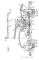
- the lifting device shown in FIG. 1 essentially consists of a hydraulic supply device 1, a sliding cylinder unit 2 and two lifting cylinder units 3 and 4, which are all arranged on a base rail 5, and a load retaining hook 6.
- the elongated base rail 5 is made of steel and has a rectangular profile with rounded outer corners. It is designed as a perforated rail with a longitudinal row of aligned holes 7 in the upper rail wall 8 and the lower rail wall 9, which are the broad sides of the rectangular profile.
- the hydraulic supply device 1 is designed in a known manner and is provided with a housing 10 which is arranged on a plate-shaped support 11 which projects forward.
- the supply device has in a known manner within the housing 10 a reservoir for oil and a pressure cylinder with a pump piston, the piston rod 12 of which is led upwards out of the housing 10 and biased upwards.
- the piston rod 12 can be depressed in the sense of a pump stroke with a pressure piece 13 which is pivotable about a horizontal pivot axis 14 arranged at a distance from the piston rod 12 and at the same time is rotatable about the piston rod axis 12.
- a tubular actuating handle 15 is inserted into the pressure piece 13 and fastened in an easily removable manner by means of a wing screw.
- oil pressure can be generated in a known manner by means of the supply device 1.
- the two lifting cylinder units 3 and 4 are designed in a completely identical manner but with mirror symmetry, as shown in FIG. 1.
- Each lifting cylinder unit has a lifting cylinder 16 with an upper cylinder head plate 17, to which a pressure-resistant flexible hose line 18 or 19 is connected.
- the two hose lines 18 and 19 are brought together in a three-way shut-off valve 20, which is connected to the pressure cylinder via a connecting line 21 and also to the reservoir of the supply device 1 via a drain valve 22.
- a reciprocating piston 23 works, which is guided downwards out of the lifting cylinder 16 and carries at its lower end a plate-shaped support shoe 24 which is articulated on the reciprocating piston 23 and can therefore perform tilting movements relative to the reciprocating piston 23, thereby providing stable support is guaranteed even when the floor is not quite level.
- each lifting cylinder 16 With the lower end of each lifting cylinder 16, a guide piece 26 in the form of a tube piece with a rectangular profile is firmly connected via a horizontally arranged connecting plate 25.
- the inner dimensions of the guide piece 26 enclosing the base rail 5 are selected such that this and thus the two lifting cylinder units 3 and 4 are guided displaceably on the base rail 5.
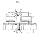
- the connecting plate 25 extends at the level of the upper wall 27 of the guide piece 26, which according to FIG. 2 has a locking opening 28 which can be aligned with a hole 7 in the upper rail wall 8, whereupon the relevant guide piece 26 and thus the associated lifting cylinder unit by means of a bolt 29 can be locked with a widened bolt head 30, as is shown in FIGS. 1 to 3 for the lifting cylinder unit 3.
- a pin 31 protrudes from the upper wall 27 of the guide piece 26, the meaning of which will be explained later.
- Each connecting plate 25 has on the front side of the base rail 5 a web 32 which is angled downwards and to which an essentially L-shaped sword claw 33 is fastened by means of screws 34.
- Each sword claw 33 consists of a horizontal support section 35 and a fastening section 36 projecting therefrom, which is tightened against the web 32 and has a stop surface 37 projecting over the heads of the screws 34.
- Each support section 35 has on its upper side a horizontal support surface 38 starting from the fastening section 36 and a sliding surface 39 which is inclined downward and adjoins this, which merges with the formation of a cutting edge 40 into the underside of the support section 35.
- the cutting edges 40 of the two sword claws 33 which extend transversely to the longitudinal direction of the rail, face each other. Otherwise, the training is made so that depressurized lifting cylinder units 3 and 4, the two sword claws 33 rest with the underside of their support section 35 on the floor.
- the sliding cylinder unit 2 is designed as a double unit with two sliding cylinders 41 and 42, which are connected to one another by a common head piece 43, which is welded onto the projecting carrier 11.
- Each sliding cylinder 41 receives a sliding piston 44 or 45, the outer end of which carries a crosspiece 46 or 47 with an eye 48 or 49.
- the eyes 48 and 49 can be plugged onto the pin 31 of the lifting cylinder unit 3 or the cylinder unit 4.
- the lower end of the locking bolt 50 can be provided with a thread 51, so that, as shown in FIG. 4, a locking nut 52 can be screwed on in order to preclude lifting of the carrier plate 11 from the base rail 5 with certainty.
- the two sliding cylinder chambers separated from each other by the head piece 43 can be acted upon separately with hydraulic oil, which can flow in via an inlet line 53 connected to the pressure cylinder of the supply device 1 with a distributor 54 and a shut-off valve 55 or 56 assigned to one of the two sliding cylinder chambers. Furthermore, separate drain lines 57 and 58 (FIG. 4) with shut-off valves 59 and 60 (FIG. 1) proceed from the two sliding cylinder chambers and are connected to the reservoir of the supply device 1.
- the sliding cylinder chambers can thus be operated by appropriate valve actuation and Pump movement of the operating lever 15 can be pressurized and relieved of pressure.
- the two sliding pistons 44 and 45 are connected to each other in a manner not shown by a connecting rod which is sealingly guided through the head piece 43rd
- the two sliding pistons 44 and 15 are moved as a unit 1 selectively to the right or to the left.
- the valves 55 and 60 are opened and closed together and alternately with the valves 56 and 59.
- a combined changeover valve can be provided, which requires a simple pivoting movement between two end positions in order to reverse the direction of movement of the sliding piston arrangement.
- the load retaining hook 6 shown in Fig. 1 is formed by a rod 61 made of a steel band which carries a load stop 62 angled at a right angle at one end and a welded pin 64 at its other end, which is provided with an opposite weaker bend 63, optionally with one of its ends in the width direction beyond the rod 61 projecting pin ends in the holes 7 of the upper rail wall 8 can be inserted.
- the lifting device is arranged on one end of the load on the floor, the lifting cylinder units 3 and 4 being moved so far apart beforehand, if necessary, that the base rail 5, via which neither the sliding cylinder unit 2 nor the supply device 1 or the associated equipment Valves protrude forward, can be placed in contact with the bulkhead or at a short distance from the bulkhead of the load. Then the two sword claws 33 enclose the front end of the load between them. Now the sword claws are successively placed under the load by means of the sliding cylinder unit 2. For example, as shown in FIG. 1, the sliding piston 45 is inserted into the pin 31 with the eye 49 suspended on the guide piece 26 of the lifting cylinder unit 4.
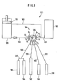
- the sword claw 33 of the lifting cylinder unit 3 is opened under open load 56 and 59 and closed valves 55 and 60 by operating the operating handle 15 of the supply device 1 in a corresponding manner, as it is for the 5 shows another lifting device, which likewise has a hydraulic supply device 101, a sliding cylinder unit 102, two lifting cylinder units 103 and 104 and a base rail 105 provided with holes 107.
- a push-off cylinder unit 165 or 166 is arranged on the side of the sword claw 133 facing away from the base rail 105 on each guide piece 126 which can be displaced on the base rail 105 in addition to the lifting cylinder unit 103 or 104 and the sword claw 133.
- Each push-off cylinder unit 165 has a push-off piston 169 which can be extended inwardly to the load in the longitudinal direction of the rail, so that the facing end faces of the push-off pistons 169 can be brought into contact with the load in order to pull the sword claws 133 back after the load has been set down and thereby take the load with them prevent, which is usually carried by the sword claw 133, which takes up the greater part of the load weight. Accordingly, a load retention hook such as the load retention hook 6 shown in FIG. 1 can be omitted, which leads to easier handling of the lifting device.
- the two lifting cylinder units 103 and 104 are connected to one another by a flexible connecting line 167 approximately in the length of the base rail 105. Accordingly, only the lifting cylinder unit 104 is connected via a flexible connecting line 168 to the supply device 101, which in turn has a pump that can be operated manually via an actuating handle 115 and a drain valve 122.
- the sliding cylinder unit 102 has only a single sliding cylinder 141 with a sliding piston 144.
- the sliding cylinder 144 has been suspended with a bolt (not shown) provided on its underside in a hole 107 in the base rail 105, the bolt being able to be secured in this position by means of a nut (not shown), as is shown in FIG. 4 for the embodiment according to FIG. 1 is shown.
- the sliding piston 144 is one connected to the sliding cylinder 141 encompassing sliding frame 143, which has at its ends pointing in the longitudinal direction of the eyes 148 and 149, which can be plugged onto the pins 131 of the guide pieces 126.
- the sliding cylinder assembly 102 can be hooked in and fastened to the base rail 105 at a suitable point, and the sliding cylinder assembly can also be pivoted through 180 ° around its fastening bolt provided on the sliding cylinder 141, so that a sliding cylinder 141 which can only be acted upon on one side is sufficient for each guide piece 126 depending on Requirement to move in or out along the base rail 105.
- the sliding cylinder unit 102 has a plug coupling connection 170, and a corresponding plug coupling connection 171 is provided on the lifting cylinder unit 104.
- the forcing cylinder units 165 and 166 are also provided with a plug-in coupling connection 172 and 173, respectively.
- the plug-in coupling connections 170 to 173 have the same size and are designed as plugs, onto which a coupling sleeve 144 can be attached at the end of the connecting line 168 facing away from the supply device 101. In this way, only a connection line 168 connected to the hydraulic supply device 101 with a simple drain valve 122 is required, since the connection line 168 can be connected to the cylinder unit, which is to be pressurized during operation of the lifting device.
- the plug-in coupling connections 170 to 173 and the coupling sleeve 174 are each provided with a valve which opens and closes automatically during the coupling process. Even when uncoupling, no oil escapes and the pressure in the cylinder assemblies does not decrease. Such quick release couplings, which are also suitable for high pressures, are commercially available.
- the hydraulic supply device 101 then has a pressure cylinder 180 with the pump piston 181 and a storage container 182, which are connected to one another via an intake line 183.
- a central switching valve 184 with a rotatable three-armed connecting channel 185 is provided with four circumferentially offset pressure connections D1 to D4, which are connected to the pressure cylinder 180 via a pressure line 186, with four circumferentially offset discharge connections A1 to A4, which via a discharge line 187 with the Storage tanks 182 are connected, and provided with four cylinder ports Z1 to Z4.
- the cylinder connection Z1 is connected via a flexible lifting line 188 to the connecting line 167 between the lifting cylinder units 103 and 104.
- the cylinder connection Z2 is connected to the sliding cylinder unit 102 via a flexible sliding line 189.
- a flexible forcing line 190 connects the forcing cylinder assembly 165 to the cylinder port Z3, and in a corresponding manner the forcing cylinder unit 166 is connected to the cylinder port Z4 via a flexible forcing line 191.
- the lifting cylinders 103 and 104 can be supplied with pressure from the pressure cylinder 180, so that the lifting device is raised as shown in FIG. 5, the lifting piston 123 with its support shoe 124 on the ground support.
- To relieve pressure of Hubzylinderaggregate 103 and 104 of the connecting channel is rotated 185 by approximately 90 0 in the counterclockwise direction, so that the terminals D1, D1 and A1 are interconnected and the entire system is depressurised, and no pressure is generated by pumps.
- the other cylinder connections Z2, Z3 and Z4 can either be connected only to the associated pressure connection D2, D3 or D4 or also additionally to the assigned drain connection A2, A3 or A4.
- the rotation position of the connecting channel 185, in which the connections D3, Z3 and A3 are connected to one another, is indicated by dash-dotted lines.
- a central changeover valve could also be provided in the embodiment according to FIG. 1, which then replaces the valves 20, 22, 55, 56, 59 and 60 and simplifies the operation of the hydraulic supply device.
Landscapes
- Life Sciences & Earth Sciences (AREA)
- Engineering & Computer Science (AREA)
- Geology (AREA)
- Mechanical Engineering (AREA)
- Structural Engineering (AREA)
- Types And Forms Of Lifts (AREA)
- Automobile Manufacture Line, Endless Track Vehicle, Trailer (AREA)
Applications Claiming Priority (2)
| Application Number | Priority Date | Filing Date | Title |
|---|---|---|---|
| DE19843403857 DE3403857A1 (de) | 1984-02-03 | 1984-02-03 | Hydraulisches hebegeraet |
| DE3403857 | 1984-02-03 |
Publications (2)
| Publication Number | Publication Date |
|---|---|
| EP0152829A2 true EP0152829A2 (fr) | 1985-08-28 |
| EP0152829A3 EP0152829A3 (fr) | 1987-12-23 |
Family
ID=6226732
Family Applications (1)
| Application Number | Title | Priority Date | Filing Date |
|---|---|---|---|
| EP85100974A Withdrawn EP0152829A3 (fr) | 1984-02-03 | 1985-01-31 | Dispositif de levage hydraulique |
Country Status (2)
| Country | Link |
|---|---|
| EP (1) | EP0152829A3 (fr) |
| DE (1) | DE3403857A1 (fr) |
Cited By (1)
| Publication number | Priority date | Publication date | Assignee | Title |
|---|---|---|---|---|
| EE201800007A (et) * | 2018-05-29 | 2020-01-15 | Lasse Ojanen | Tõsteseadmekomplekt ja selle kasutamine |
Families Citing this family (1)
| Publication number | Priority date | Publication date | Assignee | Title |
|---|---|---|---|---|
| US5203264A (en) * | 1991-10-18 | 1993-04-20 | Sodder George Jr | Re-railing unit for derailed rail car |
Family Cites Families (5)
| Publication number | Priority date | Publication date | Assignee | Title |
|---|---|---|---|---|
| DE684682C (de) * | 1936-12-14 | 1939-12-02 | App De Levage Le Mammouth Soc | Vorrichtung zur Erzielung des Gleichlaufs bei mehrsaeuligen Fluessigkeitspressen, Hebebuehnen o. dgl. |
| FR1115154A (fr) * | 1954-11-29 | 1956-04-20 | Dispositif élévateur de charges | |
| DE1741780U (de) * | 1957-01-26 | 1957-03-21 | J A Becker U Soehne | Hydraulische hebebuehnensteuerung. |
| DE2012773C2 (de) * | 1970-03-18 | 1984-12-13 | Georg Markus 7012 Fellbach Kramp | Kleinhebegerät |
| US4200419A (en) * | 1977-10-11 | 1980-04-29 | Rogers William J Jr | Assembly for positioning portable structures |
-
1984
- 1984-02-03 DE DE19843403857 patent/DE3403857A1/de not_active Withdrawn
-
1985
- 1985-01-31 EP EP85100974A patent/EP0152829A3/fr not_active Withdrawn
Cited By (2)
| Publication number | Priority date | Publication date | Assignee | Title |
|---|---|---|---|---|
| EE201800007A (et) * | 2018-05-29 | 2020-01-15 | Lasse Ojanen | Tõsteseadmekomplekt ja selle kasutamine |
| EE05827B1 (et) * | 2018-05-29 | 2020-10-15 | Lasse Ojanen | Tõsteseadmekomplekt ja selle kasutamine |
Also Published As
| Publication number | Publication date |
|---|---|
| DE3403857A1 (de) | 1985-08-08 |
| EP0152829A3 (fr) | 1987-12-23 |
Similar Documents
| Publication | Publication Date | Title |
|---|---|---|
| DE69428036T2 (de) | Rad blockierung | |
| EP1239087A1 (fr) | Accouplement rapide | |
| DE3131198A1 (de) | Teleskop-kranausleger | |
| DE2458811C3 (de) | Vorrichtung an einem Lastkraftwagen | |
| DE3707215A1 (de) | Verfahren und vorrichtung zum ausfahren eines frei auskragenden endbereichs eines kranauslegers | |
| DE1298952B (de) | Vorrichtung zum Montieren und Demontieren von Rohren oder Rohrbuendeln in laenglichen Gehaeusen, insbesondere fuer Waermeaustauscher | |
| DE10261999A1 (de) | Druckmaschine mit Trittblech zum Erreichen der oberen Farbwerke | |
| DE2640840C2 (fr) | ||
| DE3413937C2 (fr) | ||
| DE1937845C3 (de) | Hublader | |
| DE202018003699U1 (de) | Vorrichtung zum Wechseln von Stützwalzen an einem Walzgerüst | |
| EP0143197B1 (fr) | Disposition pour actionner une benne preneuse | |
| DE1506519C2 (de) | Teleskopausleger | |
| DE2758461C3 (de) | Fahrzeug mit einem an ihm anschließbaren Arbeitsgerät | |
| EP0152829A2 (fr) | Dispositif de levage hydraulique | |
| DE3007901C2 (fr) | ||
| DE2632492A1 (de) | Behaeltertransportsystem | |
| DE1268804B (de) | Teleskopausleger | |
| DE1506851A1 (de) | Selbstsynchronisierende Heb- und Senkvorrichtung fuer Portallader u.dgl. | |
| DE3632031A1 (de) | Vorbaugeraet mit zwei verschiebbaren gabelzinken | |
| DE4112017A1 (de) | Einrichtung an feuerwehrfahrzeugen oder dgl. zum be- oder entladen von geraeten | |
| DE2537521A1 (de) | Frontlader fuer traktoren | |
| DE2135371C3 (de) | Vorrichtung zum Abstützen von Transportbehältern | |
| DE1531137B1 (de) | Gegengewicht-Ausbauvorrichtung,insbesondere fuer einen auf einem Fahrgestell montierten Kran | |
| DE1928733C3 (de) | Lade- und Entladevorrichtung für sperrige Lasten |
Legal Events
| Date | Code | Title | Description |
|---|---|---|---|
| PUAI | Public reference made under article 153(3) epc to a published international application that has entered the european phase |
Free format text: ORIGINAL CODE: 0009012 |
|
| AK | Designated contracting states |
Designated state(s): AT BE CH DE FR GB IT LI NL SE |
|
| PUAL | Search report despatched |
Free format text: ORIGINAL CODE: 0009013 |
|
| AK | Designated contracting states |
Kind code of ref document: A3 Designated state(s): AT BE CH DE FR GB IT LI NL SE |
|
| 17P | Request for examination filed |
Effective date: 19880330 |
|
| 17Q | First examination report despatched |
Effective date: 19890215 |
|
| STAA | Information on the status of an ep patent application or granted ep patent |
Free format text: STATUS: THE APPLICATION IS DEEMED TO BE WITHDRAWN |
|
| 18D | Application deemed to be withdrawn |
Effective date: 19890928 |