EP0149821A2 - Plaque filtrante à membrane à contact superficiel restreint entre la plaque de support et la membrane - Google Patents
Plaque filtrante à membrane à contact superficiel restreint entre la plaque de support et la membrane Download PDFInfo
- Publication number
- EP0149821A2 EP0149821A2 EP84115803A EP84115803A EP0149821A2 EP 0149821 A2 EP0149821 A2 EP 0149821A2 EP 84115803 A EP84115803 A EP 84115803A EP 84115803 A EP84115803 A EP 84115803A EP 0149821 A2 EP0149821 A2 EP 0149821A2
- Authority
- EP
- European Patent Office
- Prior art keywords
- membrane
- carrier plate
- plate
- membrane filter
- sealing edge
- Prior art date
- Legal status (The legal status is an assumption and is not a legal conclusion. Google has not performed a legal analysis and makes no representation as to the accuracy of the status listed.)
- Ceased
Links
- 239000012528 membrane Substances 0.000 title claims abstract description 137
- 238000010438 heat treatment Methods 0.000 claims abstract description 8
- 238000007789 sealing Methods 0.000 claims description 40
- 238000001914 filtration Methods 0.000 claims description 13
- 239000002826 coolant Substances 0.000 claims description 12
- 230000007704 transition Effects 0.000 claims description 9
- 238000003825 pressing Methods 0.000 claims description 7
- 239000004744 fabric Substances 0.000 claims description 3
- 125000006850 spacer group Chemical group 0.000 claims description 2
- 230000002093 peripheral effect Effects 0.000 claims 1
- 238000001816 cooling Methods 0.000 abstract description 4
- 210000004379 membrane Anatomy 0.000 description 77
- 239000000463 material Substances 0.000 description 19
- 238000003466 welding Methods 0.000 description 11
- 238000005452 bending Methods 0.000 description 10
- 239000004033 plastic Substances 0.000 description 7
- 230000000694 effects Effects 0.000 description 4
- 239000003566 sealing material Substances 0.000 description 4
- 239000004743 Polypropylene Substances 0.000 description 3
- 230000001050 lubricating effect Effects 0.000 description 3
- 238000004519 manufacturing process Methods 0.000 description 3
- 238000000034 method Methods 0.000 description 3
- -1 polypropylene Polymers 0.000 description 3
- 229920001155 polypropylene Polymers 0.000 description 3
- 239000012815 thermoplastic material Substances 0.000 description 3
- RYGMFSIKBFXOCR-UHFFFAOYSA-N Copper Chemical compound [Cu] RYGMFSIKBFXOCR-UHFFFAOYSA-N 0.000 description 2
- 239000003795 chemical substances by application Substances 0.000 description 2
- 238000004026 adhesive bonding Methods 0.000 description 1
- 210000003423 ankle Anatomy 0.000 description 1
- 230000015572 biosynthetic process Effects 0.000 description 1
- 238000004891 communication Methods 0.000 description 1
- 230000000295 complement effect Effects 0.000 description 1
- 238000010276 construction Methods 0.000 description 1
- 238000004049 embossing Methods 0.000 description 1
- 239000012530 fluid Substances 0.000 description 1
- 239000006260 foam Substances 0.000 description 1
- 230000004313 glare Effects 0.000 description 1
- 239000008187 granular material Substances 0.000 description 1
- 238000003754 machining Methods 0.000 description 1
- 239000002184 metal Substances 0.000 description 1
- 229910052751 metal Inorganic materials 0.000 description 1
- 239000000843 powder Substances 0.000 description 1
- 238000000926 separation method Methods 0.000 description 1
- 238000007493 shaping process Methods 0.000 description 1
- 229920001169 thermoplastic Polymers 0.000 description 1
- 239000004416 thermosoftening plastic Substances 0.000 description 1
- 238000005406 washing Methods 0.000 description 1
Images


Classifications
-
- B—PERFORMING OPERATIONS; TRANSPORTING
- B01—PHYSICAL OR CHEMICAL PROCESSES OR APPARATUS IN GENERAL
- B01D—SEPARATION
- B01D35/00—Filtering devices having features not specifically covered by groups B01D24/00 - B01D33/00, or for applications not specifically covered by groups B01D24/00 - B01D33/00; Auxiliary devices for filtration; Filter housing constructions
- B01D35/18—Heating or cooling the filters
-
- B—PERFORMING OPERATIONS; TRANSPORTING
- B01—PHYSICAL OR CHEMICAL PROCESSES OR APPARATUS IN GENERAL
- B01D—SEPARATION
- B01D25/00—Filters formed by clamping together several filtering elements or parts of such elements
- B01D25/12—Filter presses, i.e. of the plate or plate and frame type
- B01D25/164—Chamber-plate presses, i.e. the sides of the filtering elements being clamped between two successive filtering plates
-
- B—PERFORMING OPERATIONS; TRANSPORTING
- B01—PHYSICAL OR CHEMICAL PROCESSES OR APPARATUS IN GENERAL
- B01D—SEPARATION
- B01D25/00—Filters formed by clamping together several filtering elements or parts of such elements
- B01D25/12—Filter presses, i.e. of the plate or plate and frame type
- B01D25/21—Plate and frame presses
- B01D25/215—Construction of the filter plates, frames
-
- B—PERFORMING OPERATIONS; TRANSPORTING
- B01—PHYSICAL OR CHEMICAL PROCESSES OR APPARATUS IN GENERAL
- B01D—SEPARATION
- B01D25/00—Filters formed by clamping together several filtering elements or parts of such elements
- B01D25/28—Leaching or washing filter cakes in the filter handling the filter cake for purposes other than regenerating
- B01D25/282—Leaching or washing filter cakes in the filter handling the filter cake for purposes other than regenerating for drying
- B01D25/285—Leaching or washing filter cakes in the filter handling the filter cake for purposes other than regenerating for drying by compression using inflatable membranes
Definitions
- the invention relates to a membrane filter plate with a reduced contact area between the carrier plate and membrane according to the preamble of claim 1.
- a difficulty with the membrane filter plates used hitherto is that the mechanical stress on the membrane is extremely high under the changing pressure stresses of the type described above, so that the membrane can easily break near the connecting line with the sealing edge.
- This disadvantage is all the more serious, since it has not been possible in the one-piece design of the membrane with the sealing edge and the carrier plate, the material properties of the membrane for high bending strength or flexibility, etc., regardless of the requirements to be placed on the carrier plate and the sealing edge to optimize.
- the invention has for its object to provide a membrane filter plate of the type mentioned, whose M em- bran over-the hitherto used has a significantly improved service life, and it should still be possible with preference, the material properties of the individual components of the membrane filter plate, in particular the M em bran itself to optimize with respect to the particular application; it should also be possible to use particularly hot or cold equipment.
- the contact surface of the carrier plate has a system of spacing cams, the reduction in the contact area between the carrier plate and membrane which is achieved in this way effectively results in a thermal separation layer between these, by which the carrier plate is prevented from being loaded during normal operation during the filtration phase with the possibly relatively high temperature of the medium to be filtered which acts on the membrane.
- This cooling effect with regard to the carrier plate is of course also promoted when a system of coolant channels is formed by the spacer cams in the manner provided according to the invention. which is also flowed through by a coolant, for example compressed air, in the filtration phase.
- the thermal decoupling of the carrier plate from the membrane achieved as a result means that even at high temperatures of, for example, 90 ° C., which were previously regarded as too high for membrane filter plates made of plastic, neither an impermissible stress on the material nor a warping of the carrier plate need be concerned.
- Such distortions always occur when the support plate is exposed in certain areas to the high temperature of the medium to be filtered, since the support plate then heats and expands to different extents due to its thickness, which varies in some areas.
- Backing plate faults of this type which of course result in corresponding faults in the entire membrane filter plate, lead to different thicknesses of the press cake produced in the pressing phase, which then results in difficulties in a washing process which may follow.
- the invention eliminates all of these difficulties in that the membrane with the relatively high temperature of the medium to be filtered is loaded, whereby as a rule its flexibility is favorably influenced in the desired manner, while the carrier plate is only loaded at a substantially lower temperature.
- the coolant flow can of course also be set so strongly that the membrane itself is significantly cooled in order to avoid its thermal overload when the medium to be filtered is at very high temperatures. It has proven useful to use membrane filter plates of the type described above in such a way that a membrane filter plate and a conventional chamber filter plate, that is to say without a membrane, are provided in succession, as a result of which the bulging of the individual membranes can be optimally utilized in the pressing phase.
- only membrane filter plates of the type according to the invention should of course be combined in a filter press in order to be able to ensure cooling of all plates in this way.
- the membrane filter plate of the type described above can, however, be used very well in the case of media to be filtered at low temperature if a heating medium is used instead of a coolant in the manner already described. In this way it is possible to process even particularly cold media to be filtered, which have hitherto been regarded as not filterable with membrane filter plates of the type in question made of plastic.
- the heating medium flowing through the heating means not only a A b-cooling of the support plate to the low temperature of preventing medium to be filtered, whereby V ER- wasfept etc. can be avoided, but since ß particular the membrane during their contact with the support plate is kept at a higher temperature than the medium to be filtered, so that the membrane in the respective pressing phase has a much higher elasticity than would be the case at the temperature of the medium to be filtered.
- the membrane remains fully movable, and damage to the membrane, in particular in the edge region, which could occur if the membrane was stiffened as a result of the temperature being too low, can be reliably prevented.
- the membrane filter plate proposed according to the invention can be produced from a large number of suitable materials.
- the carrier plate can advantageously be made from polypropylene, just as this material is also very suitable for the sealing frame. Because of the necessary tolerance requirements, however, materials that are difficult to machine are generally excluded, in the case where the required tolerance requirements could only be achieved by mechanical reworking. Rigid foams can also be used advantageously in addition to conventional thermoplastics known for such components.
- the forming process can be used advantageously for the production of membrane filter plates of the type according to the invention.
- the dowels used in various embodiments can also be produced from a large number of materials, the task of the dowels being the cohesion and the dimensional fixation of the respective one individual parts is, on the other hand, receive therein certain forces, such as substantially perpendicular to the carrier plate center plane R anddübel have the task of acting on the chamber-side
- the membrane itself is not made of a sealing material, such as rubber, to provide seals in the corners, that is to say in the vicinity of the corner bores, which of course also apply to the rest, for example Dowels arranged may be net, although this is not absolutely necessary.
- the thickness of the respective seal naturally corresponds approximately to that of the membrane, with a plus tolerance depending on the Shore hardness.
- the membranes are interchangeable. There is no complicated surface design in the sealing frame area, so that no tolerance problems can occur even when the membrane is replaced, but a perfect seal is always guaranteed.
- the sealing edge frame can also be carried out, for example, using thermoplastic materials in known and proven welded constructions. In the event that it is to be produced from thermoplastic material, the membrane can be produced, for example, by embossing or reshaping an extruder sheet, or else by primary shaping from powder or granules in the mold.
- Rubber membranes can also be easily vulcanized in the flat, uncomplicated shape provided according to the invention.
- a mold can be constructed, by means of which both plastic and rubber membranes can be produced in only one form, whereby the manufacturing costs of the membrane filter plate according to the invention can be considerably reduced.
- the membrane lies completely tight between the sealing edge frame, due to the dimensional design of the sealing edge frame and carrier plate, an edge-side, circumferential support being formed between these parts. on which the membrane rests all around and which has the effect that the membrane, in the form already specified and discussed in more detail below, has two separate hinge-like movement zones, each provided for only one direction of movement, in the relevant predetermined bending lines.
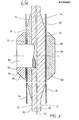
- the membrane filter plate 10 shown there in the top view has an essentially flat carrier plate surface 12 in the central area, which is made of a membrane 14 made of flexible material, such as not shown in FIG. 1 but shown in FIG Plastic, rubber or the like is covered, which in turn is sealingly held in the edge region 16 of the membrane filter plate.
- F ig. 1 further shows that a corner inlet bore 18 is provided and that the four narrow sides of the membrane 14 are each connected to one another by quarter circles with the radius R. If it is a membrane filter plate in the conventional format of 1200 x 1200 mm, the radius R is, for example, 320 mm.
- the membrane 14 which is provided on its side facing away from the carrier plate surface 12 with spacing cams 24, spacing ribs or the like for applying a filter cloth 26, is sealingly received between the edge region 16 of the carrier plate 20 and a sealing edge frame 28.
- the membrane 14 is in its unloaded normal position in the installed state, thus forming an essentially flat plate.
- the glare border frame D is connected by means of a dowel 30 with the edge region 16 of the support plate 20, wherein the plug is in the bore accommodating it was added with a clamping fit, but can also be glued or welded here, provided that the material from which the membrane 14 is made allows.
- a screw connection between the sealing frame 28 and the carrier plate 20 would also be possible.
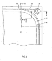
- F ig. 2 shows the corner area of a membrane filter plate with inlet and outlet bores. It can be seen that an e ckeinlaufbohrung 18 is via a channel 50 with a number of transverse bores 52 in communication, which communicate with the respective filter chamber.
- the channel 50 is milled into the surface of the sealing frame 28, just as the transverse bores 52 are open to the sealing surface of the sealing frame 28 facing the membrane 14. This results in a particularly easy machining option because the lateral ends of the channels 60 can be kept closed from the outset during the production of the sealing frame 28, which eliminates the need for subsequent filling by welding or the like.
- the open channel formation can only be used if the sealing edge frame 28 is not welded to the carrier plate 20, since of course otherwise the corresponding channels or bores or grooves could easily smear.
- the channel 50 and the transverse bores 52 are incorporated into the material of the sealing frame 28, so that this embodiment also provides easy weldability. A weld is of course out of the question if the membrane 14 is made of rubber or the like,
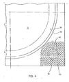
- F ig. 3 shows a corner inlet bore 18 of the type already discussed, in which the actual bore is surrounded by an annular seal 54 made of sealing material.
- This embodiment is recommended when the membrane 14 is not made of self-sealing material, for example when the membrane 14, like the carrier plate 20 or the sealing edge frame 28, is made of plastic, such as polypropylene or the like.
- corner hole 18 which of course does not serve as an inlet here, has been closed by means of a dowel 30 and then the cross-hatched corner area 56 has been welded.
- One or more corner areas 56 can be welded, for example, by resistance welding (with inserted copper wire or the like), additional holding elements being able to be used if necessary, as will be explained in more detail with reference to FIG. 6, although the holding devices shown there can also be used without any Welding of the individual membrane filter plate elements can be used.
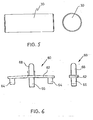
- Fig. 5 shows one of the aforementioned dowels 30, which, as shown, can be designed to taper near their ends, so as to facilitate driving into bores 18 of the type described.
- the dowels 30 therefore always run perpendicular to the center plane 22 of the carrier plate and serve either to close the holes 18 provided in the respective welding area (such as 56) for welded connections or to correspond chend their clamp fit, which can be used, for example, to secure the individual elements of the membrane filter plate within the bores 18 against forces acting parallel to the central plane of the carrier plate, that is to say radially.
- the dowels 30 can of course also absorb forces acting perpendicular to the central plane 22 of the carrier plate.
- holding chambers 60 of the type shown in FIG. 6 essentially serve to hold the membrane filter plate elements together against such forces acting perpendicularly to the center plane 22 of the carrier plate.
- the holding clamp 60 has a web and two frame pins 64 on the side lying below in FIG. 6 and a central plate pin 66.
- the frame pins 64 or the plate pins 66 are inserted into the bores of the sealing frame 28 or the edge area 16 of the carrier plate 20, the connection also taking place here with a press fit, by welding etc., as explained above in connection with the dowels 30 can.
- On the side of the web 62 opposite the plate pin 66 there is a holding pin 68 which is rounded at its free end and serves to hang the filter cloth 26 in place.
- a large number of such retaining clips 60 are provided around the membrane filter plate, so that not only reliable holding together of the membrane filter plate elements against forces acting perpendicular to the center plane of the carrier plate 22 is ensured, but also the filter cloths 26 can be adequately fastened by means of the rounded holding pins 68.
- the retaining clip 60 can preferably be made of plastic, but other materials, such as metal, are also possible.
- the web 62 is preferably, as can be seen from FIG. 6, slightly angled in order to achieve an internal tension of the retaining clip 60, which promotes the desired clamping fit of the pins 64, 66 in the bores.
- FIG. 7 shows two exemplary embodiments of a support cam which may be present in the membrane filter plate according to the invention.
- Each of the support cams has a base part 70 projecting from the support plate surface 12 essentially up to the level of the membrane 14 in its unloaded normal position, which in the embodiment according to FIG. 10, on the right, is formed in one piece with the actual support plate 20 while it is at 10, on the left, is a separate base part 70.
- the base part 70 in each case has an end face 72 which runs parallel to the carrier plate center plane 22 and a transition surface 74 which extends obliquely to the carrier plate surface 12.
- the support cam has a support part 78 projecting essentially from the plane of the membrane 14 in its unloaded normal position up to a support surface 76, from whose essentially flat support surface 76 a likewise inclined transition surface 80 runs in the direction of the membrane 14.
- Both the transition surface 74 of the base part 70 and the transition surface 80 of the support part 78 are close to theirs End surface 72 or the end facing away from the support surface 76 is stepped.
- the base part 70 and / or the support part 78 can be connected to the carrier plate 20, including the membrane 14, in various ways, for example welded, screwed or dowelled, the details 30 of which are referred to above for the dowels 30.
- a central screw 82 is shown on the left in FIG. 7, which could optionally be screwed into an internal thread of the corresponding bore of the carrier plate 20.
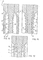
- the membrane 14 is in its unloaded normal position in the installed state, thus forming an essentially flat plate, while it is shown in FIG. 8 in the so-called filtration phase in which it is shown So in each case in the direction of the carrier plate 20 is acted upon by a medium to be filtered which is under pressure -, in the exemplary embodiment shown there, the surfaces of the carrier plate 20 facing the membrane 14 are avoiding defined bending lines than with a continuously changing bend from the carrier plate surface 12 in Central area of the carrier plate 20 formed in the edge region of the carrier plate transition surfaces 36, their transition into the edge area rich of the support plate 20 is carried out in connection with a welding drive groove 32 in the region of a connection point 38 of the membrane 14 with the sealing edge.
- the sliding surface 36 ensures that even relatively thick and less flexible membranes 14 can be used without any predetermined bending lines, without impermissible material stresses in the clamping area of the membranes near the edge. 8 and 9 also show. that the lubricating surface 36 has a flat central region approximately in the middle of the transition between the carrier plate surface 12 and the edge region 16.
- the surfaces of the carrier plate 20 facing the membranes 14 are each provided with a multiplicity of spacing cams 39, as a result of which a system of coolant channels 41 is formed in the carrier plate surface 12 and in the lubricating surface 36.
- This makes it possible to continuously form a membrane chamber 48 formed between the carrier plate 20 and the membrane 14, ie for example also in the filtration phase shown in FIG. 11, in which the membranes 14 are pressed against the carrier plate 20 under the pressure of the medium to be filtered. to act upon with coolant, which flows through so the diaphragm chamber 48 and the coolant channel system 41 continuously, thereby providing an effective thermal break between the support plate 20 and the diaphragms 1 4 is ensured.
- the spacing cams 39 are preferably beveled, as can be clearly seen in FIGS. 10 to 12, in the region of the sliding surface 36 in accordance with their general course, in order in this way to achieve a continuous bending of the membrane 14 in the various operating states.
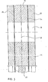
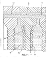
- FIG. 13 to 15 show a section of a filter press in which a membrane filter plate 10 is arranged between two camper filter plates 43 not provided with membranes.
- the "bulging effect" of the membrane 14 which can be clearly seen in FIG. 15, is used to a particularly large extent under the influence of the flow agent applied under pressure to the membrane chamber 48, which at the same time also serves as a coolant in the filtration phase shown in FIG. 14.
- the operation in each case is such that, in the filtration phase shown in FIG. 14, the fluid is introduced into the membrane chamber 48 at a significantly lower pressure, or flows through the coolant channel system 41 at a significantly lower pressure than that shown in FIG. 15 Press phase is the case.
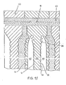
- FIG. 16 and 17 show various exemplary embodiments of the central region of a membrane filter plate with a central filtration inlet.
- the membrane 14 is sealingly connected to the support plate 20 in the sealing area surrounding the central inlet bore 84 via an annular holding piece 86, the various embodiments of which will be explained in more detail below.
- the end face 88 of the various holding pieces 86 facing away from the carrier plate 28 has a smaller distance from the carrier plate surface 12 than the circumferential surface of the sealing edge frame or the sealing edge frame 28 parallel to the carrier plate center plane 22.
- the central inlet bore 84 is surrounded at a distance by a support ring 90, the inside diameter of which is larger than the diameter of the central inlet bore 84.
- the support ring 90 has one of the left the plane of the diaphragm 14 in their unloaded normal position in the direction of the Primaeinlaugbschreibung 84 substantially obliquely to the backing plate surface 12 extending osculating 92, wherein the holding piece 86 ig wherein in F. 16 embodiment shown on the left in the area corresponding to the sliding surface 92 is designed to be complementary to the latter, so that the membrane 14 is thus held clamped between the holding piece 86 and the support ring 90.
- the two holding pieces 86 are, moreover, firmly connected to one another by a screw 94, which either interacts with a corresponding inner bore or with a lock nut or sleeve.
- An overall screw connection, as shown in FIG. 17, can also be provided.
- Holding piece 86 and / or support ring 90 can also with the carrier plate 22 and / or the membrane in a loading - ways already described are welded, bonded or v er - his ankle for. This also applies to the embodiment of the central inlet shown on the left in FIG. 17, in which the membrane 14 is formed in one piece with the holding piece 86.
- a support ring 90 also bears against the carrier plate 20 here, but this is designed in a similar manner to the sealing edge frame 28 described above in such a way that the end face 96 of the support ring 9 0 facing the membrane from its inner edge to produce two predetermined bending lines 98 , 100 is initially formed essentially parallel to the central plane 22 of the carrier plate, then extending obliquely towards it and finally stepped towards the plane 12 of the carrier plate.
- the double hinge effect already discussed above in connection with the sealing edge frame 28 is achieved when the diaphragm 14 is subjected to pressure.
- the membrane 14 is also integrally formed with the holding piece 86, but this is so thin that there is no inordinate bending stress on the membrane 14, so that the support ring can be dispensed with here . 17 also shows a clamping ring 102 passing through the central inlet bore 84 to hold the holding pieces 86 and the carrier plate 20 together, which of course can also be provided in the other shown exemplary embodiments of the central inlet.
- the individual parts of the membrane filter plate described above can consist at least partially of plastic in all of the exemplary embodiments, it being particularly important
- the advantage is that the material properties of each individual part can be optimized depending on the respective requirements.
- the membrane can be made of self-sealing material, for example rubber, and can also be replaced, which results in a wide range of variations in the possible uses of the membrane filter plate according to the invention.
- the coolant channels 41 described above can of course also be used as heating medium channels in the manner already described above (FIGS. 10 to 12). It is then possible to continuously apply the heating agent to the membrane chamber 48, which means that it continuously flows through the membrane 48 or the channel system 41, as a result of which the temperature of both the carrier plate 20 and, in particular, the elastic membrane 14 is at a higher temperature than that of the medium to be filtered can be kept.
Landscapes
- Chemical & Material Sciences (AREA)
- Chemical Kinetics & Catalysis (AREA)
- Separation Using Semi-Permeable Membranes (AREA)
- Piezo-Electric Or Mechanical Vibrators, Or Delay Or Filter Circuits (AREA)
- Filtration Of Liquid (AREA)
- Display Devices Of Pinball Game Machines (AREA)
- Polarising Elements (AREA)
Applications Claiming Priority (6)
| Application Number | Priority Date | Filing Date | Title |
|---|---|---|---|
| DE3149665 | 1981-12-15 | ||
| DE3149665 | 1981-12-15 | ||
| DE3221249 | 1982-06-04 | ||
| DE3221249 | 1982-06-04 | ||
| DE3242917 | 1982-11-20 | ||
| DE3242917 | 1982-11-20 |
Related Parent Applications (2)
| Application Number | Title | Priority Date | Filing Date |
|---|---|---|---|
| EP82110889.1 Division | 1982-11-25 | ||
| EP82110889A Division EP0081715B1 (fr) | 1981-12-15 | 1982-11-25 | Plaque filtrante à membrane |
Publications (2)
| Publication Number | Publication Date |
|---|---|
| EP0149821A2 true EP0149821A2 (fr) | 1985-07-31 |
| EP0149821A3 EP0149821A3 (fr) | 1986-09-17 |
Family
ID=27189763
Family Applications (3)
| Application Number | Title | Priority Date | Filing Date |
|---|---|---|---|
| EP84115802A Withdrawn EP0149820A3 (fr) | 1981-12-15 | 1982-11-25 | Plaque filtrante à membrane pour filtre-presse |
| EP84115803A Ceased EP0149821A3 (fr) | 1981-12-15 | 1982-11-25 | Plaque filtrante à membrane à contact superficiel restreint entre la plaque de support et la membrane |
| EP82110889A Expired EP0081715B1 (fr) | 1981-12-15 | 1982-11-25 | Plaque filtrante à membrane |
Family Applications Before (1)
| Application Number | Title | Priority Date | Filing Date |
|---|---|---|---|
| EP84115802A Withdrawn EP0149820A3 (fr) | 1981-12-15 | 1982-11-25 | Plaque filtrante à membrane pour filtre-presse |
Family Applications After (1)
| Application Number | Title | Priority Date | Filing Date |
|---|---|---|---|
| EP82110889A Expired EP0081715B1 (fr) | 1981-12-15 | 1982-11-25 | Plaque filtrante à membrane |
Country Status (4)
| Country | Link |
|---|---|
| EP (3) | EP0149820A3 (fr) |
| JP (1) | JPS58159805A (fr) |
| AT (1) | ATE20830T1 (fr) |
| DE (1) | DE3272199D1 (fr) |
Cited By (4)
| Publication number | Priority date | Publication date | Assignee | Title |
|---|---|---|---|---|
| EP0419931A1 (fr) * | 1989-09-28 | 1991-04-03 | Krupp Maschinentechnik Gesellschaft Mit Beschränkter Haftung | Presse filtrante à plaques |
| DE4136906A1 (de) * | 1991-11-09 | 1993-05-13 | Lenser Kunststoff Press | Filterplatte fuer eine filterpresse |
| DE4325235A1 (de) * | 1993-07-28 | 1995-02-02 | Junker Filter Gmbh | Filterelement für ein Kammer-, Membranfilter oder dergleichen sowie Verfahren zu seiner Herstellung |
| EP3650098A3 (fr) * | 2018-11-09 | 2020-07-29 | Krones AG | Procédé de remplissage de filtres à plaque |
Families Citing this family (10)
| Publication number | Priority date | Publication date | Assignee | Title |
|---|---|---|---|---|
| CH662087A5 (de) * | 1983-08-26 | 1987-09-15 | Bucher Guyer Ag Masch | Membranpresse zum auspressen von fluessigkeitshaltigen stoffen. |
| AU576294B2 (en) * | 1985-06-04 | 1988-08-18 | Alfred Henri Parmentier | Improvements to filter presses |
| FR2585264B1 (fr) * | 1985-06-04 | 1990-03-23 | Parmentier Alfred H | Filtres-presses |
| DE3520653A1 (de) * | 1985-06-08 | 1986-12-11 | Eberhard Hoesch & Söhne GmbH & Co, 5160 Düren | Membranplatte fuer plattenfilterpressen |
| DE8516901U1 (de) * | 1985-06-10 | 1985-08-01 | Klinkau & Co GmbH, 8952 Marktoberdorf | Membranfilterplatte mit Trägerplatte und Dichtrand |
| EP0207555B1 (fr) * | 1985-07-02 | 1989-12-27 | BREWMAR, société anonyme | Dispositif de filtrage |
| DE8605058U1 (de) * | 1986-02-25 | 1986-06-12 | Klinkau & Co GmbH, 8952 Marktoberdorf | Membranfilterplatte für eine Filterpresse od. dgl. mit Stütznocken |
| DE8806971U1 (de) * | 1988-05-27 | 1988-08-04 | Klinkau Besitzgesellschaft mbH, 8952 Marktoberdorf | Rahmenmembran für eine Membranfilterplatte und damit ausgestattete Membranfilterplatte |
| DE8817054U1 (de) * | 1988-12-19 | 1992-04-09 | Klinkau Besitzgesellschaft mbH, 8952 Marktoberdorf | Membranfilterplatte |
| CN110302569B (zh) * | 2019-08-01 | 2023-06-20 | 广东省金凯地过滤设备有限公司 | 一种加强滤布固定及密封性的压滤板 |
Citations (4)
| Publication number | Priority date | Publication date | Assignee | Title |
|---|---|---|---|---|
| DE173129C (fr) * | ||||
| DE1536844A1 (de) * | 1967-03-22 | 1970-02-26 | Krauss Maffei Ag | Filterpresse |
| DE1960821A1 (de) * | 1969-12-04 | 1971-06-09 | Hoesch & Soehne Eberhard | Pressmembran fuer Plattenfilterpressen |
| DE2720904A1 (de) * | 1977-05-10 | 1978-11-23 | Hoesch & Soehne Eberhard | Mehrteilige filterplatte |
Family Cites Families (8)
| Publication number | Priority date | Publication date | Assignee | Title |
|---|---|---|---|---|
| CH357707A (de) * | 1957-06-03 | 1961-10-31 | Ciba Geigy | Filterpressenplatte, insbesondere für Kammerfilterpressen |
| DE1761556C3 (de) * | 1968-06-06 | 1974-05-22 | Passavant Werke | Filterplatte fuer Kammer- oder Rahmenfilterpressen |
| LU65488A1 (fr) * | 1972-06-08 | 1973-12-14 | ||
| JPS5330543A (en) * | 1976-08-30 | 1978-03-22 | Katsuo Kaisa | Apparatus for preventing waterrsplashing |
| DE2652062A1 (de) * | 1976-11-15 | 1978-05-18 | Hoesch & Soehne Eberhard | Membranplatte fuer eine plattenoder rahmenfilterpresse |
| DE2712753A1 (de) * | 1977-03-23 | 1978-09-28 | Lenser Kunststoff Press | Filterplatte fuer eine filterpresse |
| DE2733769A1 (de) * | 1977-07-27 | 1979-02-15 | Lenser Kunststoff Press | Filterplatte |
| DE2933096C2 (de) * | 1979-08-16 | 1987-04-09 | Rittershaus & Blecher Gmbh, 5600 Wuppertal | Membran-Filterpresse |
-
1982
- 1982-11-25 EP EP84115802A patent/EP0149820A3/fr not_active Withdrawn
- 1982-11-25 EP EP84115803A patent/EP0149821A3/fr not_active Ceased
- 1982-11-25 DE DE8282110889T patent/DE3272199D1/de not_active Expired
- 1982-11-25 EP EP82110889A patent/EP0081715B1/fr not_active Expired
- 1982-11-25 AT AT82110889T patent/ATE20830T1/de not_active IP Right Cessation
- 1982-12-15 JP JP57220008A patent/JPS58159805A/ja active Granted
Patent Citations (4)
| Publication number | Priority date | Publication date | Assignee | Title |
|---|---|---|---|---|
| DE173129C (fr) * | ||||
| DE1536844A1 (de) * | 1967-03-22 | 1970-02-26 | Krauss Maffei Ag | Filterpresse |
| DE1960821A1 (de) * | 1969-12-04 | 1971-06-09 | Hoesch & Soehne Eberhard | Pressmembran fuer Plattenfilterpressen |
| DE2720904A1 (de) * | 1977-05-10 | 1978-11-23 | Hoesch & Soehne Eberhard | Mehrteilige filterplatte |
Cited By (7)
| Publication number | Priority date | Publication date | Assignee | Title |
|---|---|---|---|---|
| EP0419931A1 (fr) * | 1989-09-28 | 1991-04-03 | Krupp Maschinentechnik Gesellschaft Mit Beschränkter Haftung | Presse filtrante à plaques |
| DE3932422A1 (de) * | 1989-09-28 | 1991-04-11 | Krupp Maschinentechnik | Plattenfilterpresse |
| US5198123A (en) * | 1989-09-28 | 1993-03-30 | Krupp Maschinentechnik Gmbh | Plate filter press |
| DE4136906A1 (de) * | 1991-11-09 | 1993-05-13 | Lenser Kunststoff Press | Filterplatte fuer eine filterpresse |
| DE4136906C2 (de) * | 1991-11-09 | 1999-03-11 | Lenser Kunststoff Preswerk Gmb | Filterplatte für eine Filterpresse |
| DE4325235A1 (de) * | 1993-07-28 | 1995-02-02 | Junker Filter Gmbh | Filterelement für ein Kammer-, Membranfilter oder dergleichen sowie Verfahren zu seiner Herstellung |
| EP3650098A3 (fr) * | 2018-11-09 | 2020-07-29 | Krones AG | Procédé de remplissage de filtres à plaque |
Also Published As
| Publication number | Publication date |
|---|---|
| EP0081715A3 (en) | 1983-11-30 |
| EP0149820A2 (fr) | 1985-07-31 |
| ATE20830T1 (de) | 1986-08-15 |
| EP0149820A3 (fr) | 1986-09-10 |
| DE3272199D1 (en) | 1986-08-28 |
| JPH0554362B2 (fr) | 1993-08-12 |
| EP0149821A3 (fr) | 1986-09-17 |
| JPS58159805A (ja) | 1983-09-22 |
| EP0081715B1 (fr) | 1986-07-23 |
| EP0081715A2 (fr) | 1983-06-22 |
Similar Documents
| Publication | Publication Date | Title |
|---|---|---|
| EP0149821A2 (fr) | Plaque filtrante à membrane à contact superficiel restreint entre la plaque de support et la membrane | |
| EP2493587B1 (fr) | Plaque filtrante dotée d'un corps de thermorégulation et garniture de filtre dotée d'une telle plaque filtrante | |
| WO2013110800A1 (fr) | Dispositif de filtration pour la filtration à grande surface de fluides | |
| EP0155458A2 (fr) | Plaque de membrane filtrante | |
| DE112012002238B4 (de) | Ventilkörperanordnung und verfahren zu dessen herstellung sowie ventil mit der ventilkörperanordnung | |
| EP0556186B1 (fr) | Plaques-membranes pour presses a filtrer | |
| DE10221061B4 (de) | Membran, Membranplatte und Plattenpaket für eine Filterpresse | |
| DE2951150C2 (de) | Aus Metall bestehende Dichtvorrichtung an einem Hochvakuumverschluß | |
| DE3520653A1 (de) | Membranplatte fuer plattenfilterpressen | |
| EP2747865B1 (fr) | Plaque filtrante pour un filtre-presse | |
| EP1879680A1 (fr) | Filtre a courant transversal | |
| DE1928176B2 (de) | Walzenbnkettpresse zum Heißver pressen von Kohle, Erzen und ähnlichen Stoffen | |
| WO1991019120A1 (fr) | Dispositif d'etancheite | |
| DE102006022264A1 (de) | Siegelwerkzeug zum Siegeln von Folien in einer Siegelstation | |
| DE19636436C2 (de) | Preßmembran für eine Membranplatte einer Plattenfilterpresse | |
| CH626265A5 (fr) | ||
| EP0505518B1 (fr) | Plateau filtrant pour un filtre-presse a plateaux | |
| EP0233980B1 (fr) | Plaque filtrante à membrane pour filtre-presse et autre avec des bosses de support | |
| EP0208076A2 (fr) | Plaque à membrane avec plaque de support et joint périphérique | |
| EP1803548A1 (fr) | Plaque chauffante pour presse à plateaux | |
| DE202010006311U1 (de) | Filterplatte für eine Filterpresse und Filterpaket | |
| DE2720904A1 (de) | Mehrteilige filterplatte | |
| DE10246872A1 (de) | Beschichtungspresse flächiger Werkstücke | |
| EP3628387B1 (fr) | Installation de filtre | |
| DE2705560C3 (de) | Filter für Polymerschmelzen und Polymerlösungen |
Legal Events
| Date | Code | Title | Description |
|---|---|---|---|
| PUAI | Public reference made under article 153(3) epc to a published international application that has entered the european phase |
Free format text: ORIGINAL CODE: 0009012 |
|
| AC | Divisional application: reference to earlier application |
Ref document number: 81715 Country of ref document: EP |
|
| AK | Designated contracting states |
Designated state(s): AT BE CH DE FR GB IT LI |
|
| 17P | Request for examination filed |
Effective date: 19860116 |
|
| PUAL | Search report despatched |
Free format text: ORIGINAL CODE: 0009013 |
|
| AK | Designated contracting states |
Kind code of ref document: A3 Designated state(s): AT BE CH DE FR GB IT LI |
|
| 17Q | First examination report despatched |
Effective date: 19871203 |
|
| STAA | Information on the status of an ep patent application or granted ep patent |
Free format text: STATUS: THE APPLICATION HAS BEEN REFUSED |
|
| 18R | Application refused |
Effective date: 19890921 |
|
| RIN1 | Information on inventor provided before grant (corrected) |
Inventor name: KLINKAU, WERNER Inventor name: STANIK, REIMUND |