EP0149821A2 - Membrane filter-plate with limited contacting surface between the supporting plate and the membrane - Google Patents
Membrane filter-plate with limited contacting surface between the supporting plate and the membrane Download PDFInfo
- Publication number
- EP0149821A2 EP0149821A2 EP84115803A EP84115803A EP0149821A2 EP 0149821 A2 EP0149821 A2 EP 0149821A2 EP 84115803 A EP84115803 A EP 84115803A EP 84115803 A EP84115803 A EP 84115803A EP 0149821 A2 EP0149821 A2 EP 0149821A2
- Authority
- EP
- European Patent Office
- Prior art keywords
- membrane
- carrier plate
- plate
- membrane filter
- sealing edge
- Prior art date
- Legal status (The legal status is an assumption and is not a legal conclusion. Google has not performed a legal analysis and makes no representation as to the accuracy of the status listed.)
- Ceased
Links
- 239000012528 membrane Substances 0.000 title claims abstract description 137
- 238000010438 heat treatment Methods 0.000 claims abstract description 8
- 238000007789 sealing Methods 0.000 claims description 40
- 238000001914 filtration Methods 0.000 claims description 13
- 239000002826 coolant Substances 0.000 claims description 12
- 230000007704 transition Effects 0.000 claims description 9
- 238000003825 pressing Methods 0.000 claims description 7
- 239000004744 fabric Substances 0.000 claims description 3
- 125000006850 spacer group Chemical group 0.000 claims description 2
- 230000002093 peripheral effect Effects 0.000 claims 1
- 238000001816 cooling Methods 0.000 abstract description 4
- 210000004379 membrane Anatomy 0.000 description 77
- 239000000463 material Substances 0.000 description 19
- 238000003466 welding Methods 0.000 description 11
- 238000005452 bending Methods 0.000 description 10
- 239000004033 plastic Substances 0.000 description 7
- 230000000694 effects Effects 0.000 description 4
- 239000003566 sealing material Substances 0.000 description 4
- 239000004743 Polypropylene Substances 0.000 description 3
- 230000001050 lubricating effect Effects 0.000 description 3
- 238000004519 manufacturing process Methods 0.000 description 3
- 238000000034 method Methods 0.000 description 3
- -1 polypropylene Polymers 0.000 description 3
- 229920001155 polypropylene Polymers 0.000 description 3
- 239000012815 thermoplastic material Substances 0.000 description 3
- RYGMFSIKBFXOCR-UHFFFAOYSA-N Copper Chemical compound [Cu] RYGMFSIKBFXOCR-UHFFFAOYSA-N 0.000 description 2
- 239000003795 chemical substances by application Substances 0.000 description 2
- 238000004026 adhesive bonding Methods 0.000 description 1
- 210000003423 ankle Anatomy 0.000 description 1
- 230000015572 biosynthetic process Effects 0.000 description 1
- 238000004891 communication Methods 0.000 description 1
- 230000000295 complement effect Effects 0.000 description 1
- 238000010276 construction Methods 0.000 description 1
- 238000004049 embossing Methods 0.000 description 1
- 239000012530 fluid Substances 0.000 description 1
- 239000006260 foam Substances 0.000 description 1
- 230000004313 glare Effects 0.000 description 1
- 239000008187 granular material Substances 0.000 description 1
- 238000003754 machining Methods 0.000 description 1
- 239000002184 metal Substances 0.000 description 1
- 229910052751 metal Inorganic materials 0.000 description 1
- 239000000843 powder Substances 0.000 description 1
- 238000000926 separation method Methods 0.000 description 1
- 238000007493 shaping process Methods 0.000 description 1
- 229920001169 thermoplastic Polymers 0.000 description 1
- 239000004416 thermosoftening plastic Substances 0.000 description 1
- 238000005406 washing Methods 0.000 description 1
Images


Classifications
-
- B—PERFORMING OPERATIONS; TRANSPORTING
- B01—PHYSICAL OR CHEMICAL PROCESSES OR APPARATUS IN GENERAL
- B01D—SEPARATION
- B01D35/00—Filtering devices having features not specifically covered by groups B01D24/00 - B01D33/00, or for applications not specifically covered by groups B01D24/00 - B01D33/00; Auxiliary devices for filtration; Filter housing constructions
- B01D35/18—Heating or cooling the filters
-
- B—PERFORMING OPERATIONS; TRANSPORTING
- B01—PHYSICAL OR CHEMICAL PROCESSES OR APPARATUS IN GENERAL
- B01D—SEPARATION
- B01D25/00—Filters formed by clamping together several filtering elements or parts of such elements
- B01D25/12—Filter presses, i.e. of the plate or plate and frame type
- B01D25/164—Chamber-plate presses, i.e. the sides of the filtering elements being clamped between two successive filtering plates
-
- B—PERFORMING OPERATIONS; TRANSPORTING
- B01—PHYSICAL OR CHEMICAL PROCESSES OR APPARATUS IN GENERAL
- B01D—SEPARATION
- B01D25/00—Filters formed by clamping together several filtering elements or parts of such elements
- B01D25/12—Filter presses, i.e. of the plate or plate and frame type
- B01D25/21—Plate and frame presses
- B01D25/215—Construction of the filter plates, frames
-
- B—PERFORMING OPERATIONS; TRANSPORTING
- B01—PHYSICAL OR CHEMICAL PROCESSES OR APPARATUS IN GENERAL
- B01D—SEPARATION
- B01D25/00—Filters formed by clamping together several filtering elements or parts of such elements
- B01D25/28—Leaching or washing filter cakes in the filter handling the filter cake for purposes other than regenerating
- B01D25/282—Leaching or washing filter cakes in the filter handling the filter cake for purposes other than regenerating for drying
- B01D25/285—Leaching or washing filter cakes in the filter handling the filter cake for purposes other than regenerating for drying by compression using inflatable membranes
Definitions
- the invention relates to a membrane filter plate with a reduced contact area between the carrier plate and membrane according to the preamble of claim 1.
- a difficulty with the membrane filter plates used hitherto is that the mechanical stress on the membrane is extremely high under the changing pressure stresses of the type described above, so that the membrane can easily break near the connecting line with the sealing edge.
- This disadvantage is all the more serious, since it has not been possible in the one-piece design of the membrane with the sealing edge and the carrier plate, the material properties of the membrane for high bending strength or flexibility, etc., regardless of the requirements to be placed on the carrier plate and the sealing edge to optimize.
- the invention has for its object to provide a membrane filter plate of the type mentioned, whose M em- bran over-the hitherto used has a significantly improved service life, and it should still be possible with preference, the material properties of the individual components of the membrane filter plate, in particular the M em bran itself to optimize with respect to the particular application; it should also be possible to use particularly hot or cold equipment.
- the contact surface of the carrier plate has a system of spacing cams, the reduction in the contact area between the carrier plate and membrane which is achieved in this way effectively results in a thermal separation layer between these, by which the carrier plate is prevented from being loaded during normal operation during the filtration phase with the possibly relatively high temperature of the medium to be filtered which acts on the membrane.
- This cooling effect with regard to the carrier plate is of course also promoted when a system of coolant channels is formed by the spacer cams in the manner provided according to the invention. which is also flowed through by a coolant, for example compressed air, in the filtration phase.
- the thermal decoupling of the carrier plate from the membrane achieved as a result means that even at high temperatures of, for example, 90 ° C., which were previously regarded as too high for membrane filter plates made of plastic, neither an impermissible stress on the material nor a warping of the carrier plate need be concerned.
- Such distortions always occur when the support plate is exposed in certain areas to the high temperature of the medium to be filtered, since the support plate then heats and expands to different extents due to its thickness, which varies in some areas.
- Backing plate faults of this type which of course result in corresponding faults in the entire membrane filter plate, lead to different thicknesses of the press cake produced in the pressing phase, which then results in difficulties in a washing process which may follow.
- the invention eliminates all of these difficulties in that the membrane with the relatively high temperature of the medium to be filtered is loaded, whereby as a rule its flexibility is favorably influenced in the desired manner, while the carrier plate is only loaded at a substantially lower temperature.
- the coolant flow can of course also be set so strongly that the membrane itself is significantly cooled in order to avoid its thermal overload when the medium to be filtered is at very high temperatures. It has proven useful to use membrane filter plates of the type described above in such a way that a membrane filter plate and a conventional chamber filter plate, that is to say without a membrane, are provided in succession, as a result of which the bulging of the individual membranes can be optimally utilized in the pressing phase.
- only membrane filter plates of the type according to the invention should of course be combined in a filter press in order to be able to ensure cooling of all plates in this way.
- the membrane filter plate of the type described above can, however, be used very well in the case of media to be filtered at low temperature if a heating medium is used instead of a coolant in the manner already described. In this way it is possible to process even particularly cold media to be filtered, which have hitherto been regarded as not filterable with membrane filter plates of the type in question made of plastic.
- the heating medium flowing through the heating means not only a A b-cooling of the support plate to the low temperature of preventing medium to be filtered, whereby V ER- wasfept etc. can be avoided, but since ß particular the membrane during their contact with the support plate is kept at a higher temperature than the medium to be filtered, so that the membrane in the respective pressing phase has a much higher elasticity than would be the case at the temperature of the medium to be filtered.
- the membrane remains fully movable, and damage to the membrane, in particular in the edge region, which could occur if the membrane was stiffened as a result of the temperature being too low, can be reliably prevented.
- the membrane filter plate proposed according to the invention can be produced from a large number of suitable materials.
- the carrier plate can advantageously be made from polypropylene, just as this material is also very suitable for the sealing frame. Because of the necessary tolerance requirements, however, materials that are difficult to machine are generally excluded, in the case where the required tolerance requirements could only be achieved by mechanical reworking. Rigid foams can also be used advantageously in addition to conventional thermoplastics known for such components.
- the forming process can be used advantageously for the production of membrane filter plates of the type according to the invention.
- the dowels used in various embodiments can also be produced from a large number of materials, the task of the dowels being the cohesion and the dimensional fixation of the respective one individual parts is, on the other hand, receive therein certain forces, such as substantially perpendicular to the carrier plate center plane R anddübel have the task of acting on the chamber-side
- the membrane itself is not made of a sealing material, such as rubber, to provide seals in the corners, that is to say in the vicinity of the corner bores, which of course also apply to the rest, for example Dowels arranged may be net, although this is not absolutely necessary.
- the thickness of the respective seal naturally corresponds approximately to that of the membrane, with a plus tolerance depending on the Shore hardness.
- the membranes are interchangeable. There is no complicated surface design in the sealing frame area, so that no tolerance problems can occur even when the membrane is replaced, but a perfect seal is always guaranteed.
- the sealing edge frame can also be carried out, for example, using thermoplastic materials in known and proven welded constructions. In the event that it is to be produced from thermoplastic material, the membrane can be produced, for example, by embossing or reshaping an extruder sheet, or else by primary shaping from powder or granules in the mold.
- Rubber membranes can also be easily vulcanized in the flat, uncomplicated shape provided according to the invention.
- a mold can be constructed, by means of which both plastic and rubber membranes can be produced in only one form, whereby the manufacturing costs of the membrane filter plate according to the invention can be considerably reduced.
- the membrane lies completely tight between the sealing edge frame, due to the dimensional design of the sealing edge frame and carrier plate, an edge-side, circumferential support being formed between these parts. on which the membrane rests all around and which has the effect that the membrane, in the form already specified and discussed in more detail below, has two separate hinge-like movement zones, each provided for only one direction of movement, in the relevant predetermined bending lines.
- the membrane filter plate 10 shown there in the top view has an essentially flat carrier plate surface 12 in the central area, which is made of a membrane 14 made of flexible material, such as not shown in FIG. 1 but shown in FIG Plastic, rubber or the like is covered, which in turn is sealingly held in the edge region 16 of the membrane filter plate.
- F ig. 1 further shows that a corner inlet bore 18 is provided and that the four narrow sides of the membrane 14 are each connected to one another by quarter circles with the radius R. If it is a membrane filter plate in the conventional format of 1200 x 1200 mm, the radius R is, for example, 320 mm.
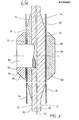
- the membrane 14 which is provided on its side facing away from the carrier plate surface 12 with spacing cams 24, spacing ribs or the like for applying a filter cloth 26, is sealingly received between the edge region 16 of the carrier plate 20 and a sealing edge frame 28.
- the membrane 14 is in its unloaded normal position in the installed state, thus forming an essentially flat plate.
- the glare border frame D is connected by means of a dowel 30 with the edge region 16 of the support plate 20, wherein the plug is in the bore accommodating it was added with a clamping fit, but can also be glued or welded here, provided that the material from which the membrane 14 is made allows.
- a screw connection between the sealing frame 28 and the carrier plate 20 would also be possible.
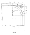
- F ig. 2 shows the corner area of a membrane filter plate with inlet and outlet bores. It can be seen that an e ckeinlaufbohrung 18 is via a channel 50 with a number of transverse bores 52 in communication, which communicate with the respective filter chamber.
- the channel 50 is milled into the surface of the sealing frame 28, just as the transverse bores 52 are open to the sealing surface of the sealing frame 28 facing the membrane 14. This results in a particularly easy machining option because the lateral ends of the channels 60 can be kept closed from the outset during the production of the sealing frame 28, which eliminates the need for subsequent filling by welding or the like.
- the open channel formation can only be used if the sealing edge frame 28 is not welded to the carrier plate 20, since of course otherwise the corresponding channels or bores or grooves could easily smear.
- the channel 50 and the transverse bores 52 are incorporated into the material of the sealing frame 28, so that this embodiment also provides easy weldability. A weld is of course out of the question if the membrane 14 is made of rubber or the like,
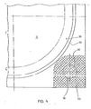
- F ig. 3 shows a corner inlet bore 18 of the type already discussed, in which the actual bore is surrounded by an annular seal 54 made of sealing material.
- This embodiment is recommended when the membrane 14 is not made of self-sealing material, for example when the membrane 14, like the carrier plate 20 or the sealing edge frame 28, is made of plastic, such as polypropylene or the like.
- corner hole 18 which of course does not serve as an inlet here, has been closed by means of a dowel 30 and then the cross-hatched corner area 56 has been welded.
- One or more corner areas 56 can be welded, for example, by resistance welding (with inserted copper wire or the like), additional holding elements being able to be used if necessary, as will be explained in more detail with reference to FIG. 6, although the holding devices shown there can also be used without any Welding of the individual membrane filter plate elements can be used.
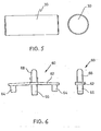
- Fig. 5 shows one of the aforementioned dowels 30, which, as shown, can be designed to taper near their ends, so as to facilitate driving into bores 18 of the type described.
- the dowels 30 therefore always run perpendicular to the center plane 22 of the carrier plate and serve either to close the holes 18 provided in the respective welding area (such as 56) for welded connections or to correspond chend their clamp fit, which can be used, for example, to secure the individual elements of the membrane filter plate within the bores 18 against forces acting parallel to the central plane of the carrier plate, that is to say radially.
- the dowels 30 can of course also absorb forces acting perpendicular to the central plane 22 of the carrier plate.
- holding chambers 60 of the type shown in FIG. 6 essentially serve to hold the membrane filter plate elements together against such forces acting perpendicularly to the center plane 22 of the carrier plate.
- the holding clamp 60 has a web and two frame pins 64 on the side lying below in FIG. 6 and a central plate pin 66.
- the frame pins 64 or the plate pins 66 are inserted into the bores of the sealing frame 28 or the edge area 16 of the carrier plate 20, the connection also taking place here with a press fit, by welding etc., as explained above in connection with the dowels 30 can.
- On the side of the web 62 opposite the plate pin 66 there is a holding pin 68 which is rounded at its free end and serves to hang the filter cloth 26 in place.
- a large number of such retaining clips 60 are provided around the membrane filter plate, so that not only reliable holding together of the membrane filter plate elements against forces acting perpendicular to the center plane of the carrier plate 22 is ensured, but also the filter cloths 26 can be adequately fastened by means of the rounded holding pins 68.
- the retaining clip 60 can preferably be made of plastic, but other materials, such as metal, are also possible.
- the web 62 is preferably, as can be seen from FIG. 6, slightly angled in order to achieve an internal tension of the retaining clip 60, which promotes the desired clamping fit of the pins 64, 66 in the bores.
- FIG. 7 shows two exemplary embodiments of a support cam which may be present in the membrane filter plate according to the invention.
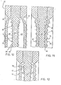
- Each of the support cams has a base part 70 projecting from the support plate surface 12 essentially up to the level of the membrane 14 in its unloaded normal position, which in the embodiment according to FIG. 10, on the right, is formed in one piece with the actual support plate 20 while it is at 10, on the left, is a separate base part 70.
- the base part 70 in each case has an end face 72 which runs parallel to the carrier plate center plane 22 and a transition surface 74 which extends obliquely to the carrier plate surface 12.
- the support cam has a support part 78 projecting essentially from the plane of the membrane 14 in its unloaded normal position up to a support surface 76, from whose essentially flat support surface 76 a likewise inclined transition surface 80 runs in the direction of the membrane 14.
- Both the transition surface 74 of the base part 70 and the transition surface 80 of the support part 78 are close to theirs End surface 72 or the end facing away from the support surface 76 is stepped.
- the base part 70 and / or the support part 78 can be connected to the carrier plate 20, including the membrane 14, in various ways, for example welded, screwed or dowelled, the details 30 of which are referred to above for the dowels 30.
- a central screw 82 is shown on the left in FIG. 7, which could optionally be screwed into an internal thread of the corresponding bore of the carrier plate 20.
- the membrane 14 is in its unloaded normal position in the installed state, thus forming an essentially flat plate, while it is shown in FIG. 8 in the so-called filtration phase in which it is shown So in each case in the direction of the carrier plate 20 is acted upon by a medium to be filtered which is under pressure -, in the exemplary embodiment shown there, the surfaces of the carrier plate 20 facing the membrane 14 are avoiding defined bending lines than with a continuously changing bend from the carrier plate surface 12 in Central area of the carrier plate 20 formed in the edge region of the carrier plate transition surfaces 36, their transition into the edge area rich of the support plate 20 is carried out in connection with a welding drive groove 32 in the region of a connection point 38 of the membrane 14 with the sealing edge.
- the sliding surface 36 ensures that even relatively thick and less flexible membranes 14 can be used without any predetermined bending lines, without impermissible material stresses in the clamping area of the membranes near the edge. 8 and 9 also show. that the lubricating surface 36 has a flat central region approximately in the middle of the transition between the carrier plate surface 12 and the edge region 16.
- the surfaces of the carrier plate 20 facing the membranes 14 are each provided with a multiplicity of spacing cams 39, as a result of which a system of coolant channels 41 is formed in the carrier plate surface 12 and in the lubricating surface 36.
- This makes it possible to continuously form a membrane chamber 48 formed between the carrier plate 20 and the membrane 14, ie for example also in the filtration phase shown in FIG. 11, in which the membranes 14 are pressed against the carrier plate 20 under the pressure of the medium to be filtered. to act upon with coolant, which flows through so the diaphragm chamber 48 and the coolant channel system 41 continuously, thereby providing an effective thermal break between the support plate 20 and the diaphragms 1 4 is ensured.
- the spacing cams 39 are preferably beveled, as can be clearly seen in FIGS. 10 to 12, in the region of the sliding surface 36 in accordance with their general course, in order in this way to achieve a continuous bending of the membrane 14 in the various operating states.
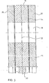
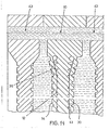
- FIG. 13 to 15 show a section of a filter press in which a membrane filter plate 10 is arranged between two camper filter plates 43 not provided with membranes.
- the "bulging effect" of the membrane 14 which can be clearly seen in FIG. 15, is used to a particularly large extent under the influence of the flow agent applied under pressure to the membrane chamber 48, which at the same time also serves as a coolant in the filtration phase shown in FIG. 14.
- the operation in each case is such that, in the filtration phase shown in FIG. 14, the fluid is introduced into the membrane chamber 48 at a significantly lower pressure, or flows through the coolant channel system 41 at a significantly lower pressure than that shown in FIG. 15 Press phase is the case.
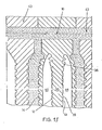
- FIG. 16 and 17 show various exemplary embodiments of the central region of a membrane filter plate with a central filtration inlet.
- the membrane 14 is sealingly connected to the support plate 20 in the sealing area surrounding the central inlet bore 84 via an annular holding piece 86, the various embodiments of which will be explained in more detail below.
- the end face 88 of the various holding pieces 86 facing away from the carrier plate 28 has a smaller distance from the carrier plate surface 12 than the circumferential surface of the sealing edge frame or the sealing edge frame 28 parallel to the carrier plate center plane 22.
- the central inlet bore 84 is surrounded at a distance by a support ring 90, the inside diameter of which is larger than the diameter of the central inlet bore 84.
- the support ring 90 has one of the left the plane of the diaphragm 14 in their unloaded normal position in the direction of the Primaeinlaugbschreibung 84 substantially obliquely to the backing plate surface 12 extending osculating 92, wherein the holding piece 86 ig wherein in F. 16 embodiment shown on the left in the area corresponding to the sliding surface 92 is designed to be complementary to the latter, so that the membrane 14 is thus held clamped between the holding piece 86 and the support ring 90.
- the two holding pieces 86 are, moreover, firmly connected to one another by a screw 94, which either interacts with a corresponding inner bore or with a lock nut or sleeve.
- An overall screw connection, as shown in FIG. 17, can also be provided.
- Holding piece 86 and / or support ring 90 can also with the carrier plate 22 and / or the membrane in a loading - ways already described are welded, bonded or v er - his ankle for. This also applies to the embodiment of the central inlet shown on the left in FIG. 17, in which the membrane 14 is formed in one piece with the holding piece 86.
- a support ring 90 also bears against the carrier plate 20 here, but this is designed in a similar manner to the sealing edge frame 28 described above in such a way that the end face 96 of the support ring 9 0 facing the membrane from its inner edge to produce two predetermined bending lines 98 , 100 is initially formed essentially parallel to the central plane 22 of the carrier plate, then extending obliquely towards it and finally stepped towards the plane 12 of the carrier plate.
- the double hinge effect already discussed above in connection with the sealing edge frame 28 is achieved when the diaphragm 14 is subjected to pressure.
- the membrane 14 is also integrally formed with the holding piece 86, but this is so thin that there is no inordinate bending stress on the membrane 14, so that the support ring can be dispensed with here . 17 also shows a clamping ring 102 passing through the central inlet bore 84 to hold the holding pieces 86 and the carrier plate 20 together, which of course can also be provided in the other shown exemplary embodiments of the central inlet.
- the individual parts of the membrane filter plate described above can consist at least partially of plastic in all of the exemplary embodiments, it being particularly important
- the advantage is that the material properties of each individual part can be optimized depending on the respective requirements.
- the membrane can be made of self-sealing material, for example rubber, and can also be replaced, which results in a wide range of variations in the possible uses of the membrane filter plate according to the invention.
- the coolant channels 41 described above can of course also be used as heating medium channels in the manner already described above (FIGS. 10 to 12). It is then possible to continuously apply the heating agent to the membrane chamber 48, which means that it continuously flows through the membrane 48 or the channel system 41, as a result of which the temperature of both the carrier plate 20 and, in particular, the elastic membrane 14 is at a higher temperature than that of the medium to be filtered can be kept.
Landscapes
- Chemical & Material Sciences (AREA)
- Chemical Kinetics & Catalysis (AREA)
- Separation Using Semi-Permeable Membranes (AREA)
- Filtration Of Liquid (AREA)
- Piezo-Electric Or Mechanical Vibrators, Or Delay Or Filter Circuits (AREA)
- Display Devices Of Pinball Game Machines (AREA)
- Polarising Elements (AREA)
Abstract
Description
Die Erfindung betrifft eine Membranfilterplatte mit verringerter Kontaktfläche zwischen Trägerplatte und Membran nach dem Oberbegriff des Patentanspruches 1.The invention relates to a membrane filter plate with a reduced contact area between the carrier plate and membrane according to the preamble of
Eine Schwierigkeit besteht bei den bislang verwendeten Membranfilterplatten darin, daß die mechanische Beanspruchung der Membran bei den wechselnden Druckbeanspruchungen der vorstehend beschriebenen Art außerordentlich hoch ist, so daß es leicht zu einem Bruch der Membran nahe der Verbindungslinie mit dem Dichtrand kommen kann. Dieser Nachteil wiegt umso schwerer, als es bei der bislang weitestgehend gehandhabten einstückigen Ausbildung der Membran mit dem Dichtrand und der Trägerplatte nicht möglich ist, die Materialeigenschaften der Membran unabhängig von den an die Trägerplatte und den Dichtrand zu stellenden Anforderungen auf hohe Biegefestigkeit bzw. Flexibilität etc. zu optimieren.A difficulty with the membrane filter plates used hitherto is that the mechanical stress on the membrane is extremely high under the changing pressure stresses of the type described above, so that the membrane can easily break near the connecting line with the sealing edge. This disadvantage is all the more serious, since it has not been possible in the one-piece design of the membrane with the sealing edge and the carrier plate, the material properties of the membrane for high bending strength or flexibility, etc., regardless of the requirements to be placed on the carrier plate and the sealing edge to optimize.
Aus der DE-A-2 933 096 ist eine Membranfilterplatte der eingangs genannten Art bekannt, bei der die Auslenkung der Membran in der Filtrations- wie in der Abpreßphase durch Biegung um eine einzige, scharnierartige Sollbiegelinie erfolgt. Hierdurch treten beträchtliche Materialbeanspruchungen auf, die zu frühzeitigen Ermüdungserscheinungen führen können.From DE-A-2 933 096 a membrane filter plate of the type mentioned is known, in which the deflection of the membrane in the filtration and in the pressing-off phase takes place by bending around a single, hinge-like predetermined bending line. This causes considerable material stresses, which can lead to early signs of fatigue.
Dabei ist insbesondere nicht die wünschenswerte Variabilität in der Temperatur der Betriebsmedien gegeben.In particular, the desirable variability in the temperature of the operating media is not given.
Der Erfindung liegt die Aufgabe zugrunde, eine Membranfilterplatte der eingangs genannten Art zu schaffen, deren Mem- bran gegenüber-den bislang verwendeten eine wesentlich verbesserte Lebensdauer aufweist, wobei es weiterhin bevorzugt möglich sein soll, die Materialeigenschaften der einzelnen Bauelemente der Membranfilterplatte, insbesondere der Mem- bran selbst, im Hinblick auf den jeweiligen Anwendungszweck zu optimieren; dabei sollen auch besonders heiße bzw. kalte Betriebsmittel verwendet werden können.The invention has for its object to provide a membrane filter plate of the type mentioned, whose M em- bran over-the hitherto used has a significantly improved service life, and it should still be possible with preference, the material properties of the individual components of the membrane filter plate, in particular the M em bran itself to optimize with respect to the particular application; it should also be possible to use particularly hot or cold equipment.
Erfindungsgemäß wird diese Aufgabe durch die im Kennzeichen des Patentanspruches 1 aufgeführten Merkmale gelöst.According to the invention, this object is achieved by the features listed in the characterizing part of
Weist die Anlagefläche der Trägerplatte, wie dies weiter oben beschrieben und auch beansprucht ist, ein System von Abstandnocken auf, so bewirkt die hierdurch erzielte Verringerung der Kontaktfläche zwischen Trägerplatte und Membran gewissermaßen eine thermische Trennschicht zwischen diesen, durch welche verhindert wird, daß die Trägerplatte im Normalbetrieb während der Filtrationsphase mit der gegebenenfalls relativ hohen Temperatur des zu filternden Mediums, welches die Membran beaufschlagt, belastet wird. Gefördert wird diese Kühlwirkung hinsichtlich der Trägerplatte natürlich noch dann, wenn in der erfindungsgemäß vorgesehenen Weise durch die Abstandsnocken ein System von Kühlmittelkanälen gebildet. ist, welches auch in der Filtrationsphase von einem Kühlmittel, beispielsweise Preßluft, durchströmt ist. Die hierdurch insgesamt erzielte thermische Entkopplung der Trägerplatte von der Membran bewirkt, daß auch bei hohen Temperaturen von beispielsweise 90° C, die bislang als für aus Kunststoff hergestellte Membranfilterplatten zu hoch angesehen wurden, weder eine unzulässige Materialbeanspruchung noch eine Verwerfung der Trägerplatte zu besorgen sind. Derartige Verwerfungen treten immer dann auf, wenn die Trägerplatte bereichsweise mit der hohen Temperatur des zu filternden Mediums belastet wird, da die Trägerplatte sich dann wegen ihrer bereichsweise unterschiedlichen Dicke jeweils unterschiedlich stark erwärmt und ausdehnt. Trägerplattenverwerfungen dieser Art, die natürlich entsprechende Verwerfungen der gesamten Membranfilterplatte zur Folge haben, führen zu unterschiedlichen Dicken des in der Preßphase erzeugten Preßkuchens, woraus dann Schwierigkeiten bei einem gegebenenfalls sich anschließenden Waschvorgang resultieren. Die Erfindung beseitigt all diese Schwierigkeiten dadurch, daß zwar die Membran mit der relativ hohen Temperatur des zu filternden Mediums belastet wird, wodurch in der Regel deren Flexibilität aber in gewünschter Weise günstig beeinflußt wird, während die Trägerplatte nur mit einer wesentlich niedrigeren Temperatur belastet wird. Gewünschtenfalls kann natürlich der Kühlmittelstrom auch so stark eingestellt werden, daß die Membran selbst deutlich gekühlt wird, um bei sehr hohen Temperaturen des zu filternden Mediums deren thermische Überbeanspruchung zu vermeiden. Es hat sich bewährt, Membranfilterplatten der vorstehend beschriebenen Art so einzusetzen, daß jeweils aufeinanderfolgend eine Membranfilterplatte und eine herkömmliche Kammerfilterplatte, also ohne Membran, vorgesehen sind, wodurch die Auswölbung der einzelnen Membranen in der Preßphase optimal ausgenutzt werden kann. Bei zu filternden Medien mit sehr hohen Temperaturen sollen selbstverständlich nur Membranfilterplatten der erfindungsgemäßen Art in einer Filterpresse vereinigt werden, um auf diese Weise für eine Kühlung sämtlicher Platten Sorge tragen zu können.If the contact surface of the carrier plate, as described above and also claimed, has a system of spacing cams, the reduction in the contact area between the carrier plate and membrane which is achieved in this way effectively results in a thermal separation layer between these, by which the carrier plate is prevented from being loaded during normal operation during the filtration phase with the possibly relatively high temperature of the medium to be filtered which acts on the membrane. This cooling effect with regard to the carrier plate is of course also promoted when a system of coolant channels is formed by the spacer cams in the manner provided according to the invention. which is also flowed through by a coolant, for example compressed air, in the filtration phase. The thermal decoupling of the carrier plate from the membrane achieved as a result means that even at high temperatures of, for example, 90 ° C., which were previously regarded as too high for membrane filter plates made of plastic, neither an impermissible stress on the material nor a warping of the carrier plate need be worried. Such distortions always occur when the support plate is exposed in certain areas to the high temperature of the medium to be filtered, since the support plate then heats and expands to different extents due to its thickness, which varies in some areas. Backing plate faults of this type, which of course result in corresponding faults in the entire membrane filter plate, lead to different thicknesses of the press cake produced in the pressing phase, which then results in difficulties in a washing process which may follow. The invention eliminates all of these difficulties in that the membrane with the relatively high temperature of the medium to be filtered is loaded, whereby as a rule its flexibility is favorably influenced in the desired manner, while the carrier plate is only loaded at a substantially lower temperature. If desired, the coolant flow can of course also be set so strongly that the membrane itself is significantly cooled in order to avoid its thermal overload when the medium to be filtered is at very high temperatures. It has proven useful to use membrane filter plates of the type described above in such a way that a membrane filter plate and a conventional chamber filter plate, that is to say without a membrane, are provided in succession, as a result of which the bulging of the individual membranes can be optimally utilized in the pressing phase. In the case of media to be filtered with very high temperatures, only membrane filter plates of the type according to the invention should of course be combined in a filter press in order to be able to ensure cooling of all plates in this way.
Bei Membranfilterplatten treten aber nicht nur dann Probleme auf, wenn diese bei hohen Temperaturen von beispielsweise 90° C eingesetzt werden sollen, vielmehr ist es auch schwierig, zu filternde Medien mit besonders niedriger Temperatur, insbesondere unterhalb Raumtemperatur, erst recht aber bei Temperaturen unterhalb von 0°C, zu behandeln, da hierdurch ebenfalls Verwerfungen der Trägerplatte auftreten können, wenn diese mit der niedrigen Temperatur des zu filternden Mediums beaufschlagt wird, insbesondere aber die Membran selbst weitgehend ihre Elastizität verliert, so daß bei den in der Preßphase notwendigen Membranbewegungen starke Materialbeanspruchungen der Membran insbesondere an der Einspannstelle auftreten, woraus Ermüdungsbrüche und sonstige Beschädigungen resultieren können. Die Membranfilterplatte der vorstehend beschriebenen Art läßt sich aber bei zu filternden Medien niedriger Temperatur sehr gut einsetzen, wenn in der bereits beschriebenen Weise statt eines Kühlmittels ein Heizmittel verwendet wird. Hierdurch gelingt es, auch besonders kalte zu' filternde Medien zu verarbeiten, die bislang als mit aus Kunststoff hergestellten Membranfilterplatten der in Rede stehenden Art nicht filtrierbar angesehen wurden.Problems do not only arise with membrane filter plates if they are to be used at high temperatures of, for example, 90 ° C., it is also difficult to filter media at a particularly low temperature, in particular below room temperature, and even more so at temperatures below 0 ° C to treat, since this can also cause warping of the support plate if this with the low temperature of the medium to be filtered is applied, but in particular the membrane itself largely loses its elasticity, so that during the membrane movements necessary in the pressing phase strong material stresses of the membrane occur in particular at the clamping point, which can result in fatigue fractures and other damage. The membrane filter plate of the type described above can, however, be used very well in the case of media to be filtered at low temperature if a heating medium is used instead of a coolant in the manner already described. In this way it is possible to process even particularly cold media to be filtered, which have hitherto been regarded as not filterable with membrane filter plates of the type in question made of plastic.
Der Grund hierfür liegt darin, daß das die Heizmittelkanäle durchströmende Heizmittel nicht nur eine Ab-kühlung der Trägerplatte auf die niedrige Temperatur des zu filternden Mediums verhindert, wodurch Ver- werfungen etc. vermieden werden können, sondern daß insbesondere auch die Membran während ihrer Anlage an der Trägerplatte auf einer höheren Temperatur als das zu filternde Medium gehalten wird, so daß die Membran in der jeweiligen Preßphase eine wesentlich höhere Elastizität hat, als dies bei der Temperatur des zu filternden Mediums der Fall wäre. Hierdurch bleibt die Membran voll beweglich, und Beschädigungen derselben, insbesondere im Randbereich, wie sie bei einer Versteifung der Membran infolge zu niedriger Temperatur auftreten könnten, lassen sich zuverlässig verhindern.The reason for this is that the the heating medium flowing through the heating means not only a A b-cooling of the support plate to the low temperature of preventing medium to be filtered, whereby V ER- werfungen etc. can be avoided, but since ß particular the membrane during their contact with the support plate is kept at a higher temperature than the medium to be filtered, so that the membrane in the respective pressing phase has a much higher elasticity than would be the case at the temperature of the medium to be filtered. As a result, the membrane remains fully movable, and damage to the membrane, in particular in the edge region, which could occur if the membrane was stiffened as a result of the temperature being too low, can be reliably prevented.
Es sei darauf hingewiesen, daß unter dem Ausdruck "schräg", soweit er in Verbindung mit dem Verlauf der Anlagefläche der Trägerplatte auf die Trägerplattenmittelebene hin bzw. in Verbindung mit der Übergangsfläche des Basisteiles und/oder des Stützteiles sowie in Verbindung mit der Schmiegefläche des Stützringes und schließlich auch der Stirnfläche des stützringes in ihrem Verlauf auf die Trägerplattenmittelebene hin verwendet wird, ein Winkel von 3 bis 15°, vorzugsweise 5 bis 10°, verstanden wird.It should be noted that under the term "oblique", insofar as it is in connection with the course of the contact surface of the carrier plate on the carrier plate center plane or in connection with the transition surface of the base part and / or the support part and in connection with the lubricating surface of the support ring and finally also the end face of the support ring is used in its course towards the carrier plate center plane, an angle of 3 to 15 °, preferably 5 to 10 °, is understood.
Die erfindungsgemäß vorgeschlagene Membranfilterplatte kann aus einer Vielzahl geeigneter Werkstoffe hergestellt werden. Beispielsweise kann die Trägerplatte in vorteilhafter Weise aus Polypropylen hergestellt werden, ebenso wie dieses Material auch sehr gut für den Dichtrandrahmen geeignet ist. Wegen der notwendigen Toleranzanforderungen scheiden allerdings schwer bearbeitbare Materialien in der Regel aus, in dem Fall nämlich, in dem die erforderlichen Toleranzanforderungen nur durch eine mechanische Nacharbeit erreicht werden könnten. Auch Hartschaumstoffe lassen sich zusätzlich zu herkömmlichen, für derartige Bauteile bekannten Thermoplasten in vorteilhafter Weise verwenden.The membrane filter plate proposed according to the invention can be produced from a large number of suitable materials. For example, the carrier plate can advantageously be made from polypropylene, just as this material is also very suitable for the sealing frame. Because of the necessary tolerance requirements, however, materials that are difficult to machine are generally excluded, in the case where the required tolerance requirements could only be achieved by mechanical reworking. Rigid foams can also be used advantageously in addition to conventional thermoplastics known for such components.
Werden thermoplastische Kunststoffe eingesetzt, so läßt sich das Umformverfahren in vorteilhafter Weise zur Herstellung von Membranfilterplatten der erfindungsgemäßen Art verwenden. Die bei verschiedenen Ausführungsformen verwendeten Dübel lassen sich ebenfalls aus einer Vielzahl von Werkstoffen herstellen, wobei die Aufgabe der Dübel einmal im Zusammenhalt und der maßlichen Fixierung der jeweiligen Einzelteile besteht, zum anderen aber auch darin, bestimmte Kräfte aufzunehmen, so wie beispielsweise die im wesentlichen senkrecht zur Trägerplattenmittelebene verlaufenden Randdübel die Aufgabe haben, die auf die kammerseitigeIf thermoplastic materials are used, the forming process can be used advantageously for the production of membrane filter plates of the type according to the invention. The dowels used in various embodiments can also be produced from a large number of materials, the task of the dowels being the cohesion and the dimensional fixation of the respective one individual parts is, on the other hand, receive therein certain forces, such as substantially perpendicular to the carrier plate center plane R anddübel have the task of acting on the chamber-side
Schräge des Dichtrandes wirkende Innenkraft (Filtrationsdruck), soweit diese Kraftkomponente nicht durch die Reibungskraft in Dichtrandbereich, also durch den Schließdruck, ausgeglichen werden kann, .auf die Trägerplatte zu übertragen, damit ein Ausbiegen des Dichtrandes verhindert wird. Die erforderliche Anzahl sowie die Dimensionierung der Dübel, auch letzten Endes die Teilung und das Dübelmaterial ergeben sich in für den Fachmann ohne weiteres ersichtlicher Weise aus den jeweiligen konstruktiven Voraussetzungen.Transferring the internal force of the sealing edge (filtration pressure), insofar as this force component cannot be compensated by the frictional force in the sealing edge area, i.e. by the closing pressure, to be transferred to the carrier plate so that the sealing edge is prevented from bending out. The required number and the dimensioning of the dowels, and ultimately also the division and the dowel material, are readily apparent to the person skilled in the art from the respective structural requirements.
Auch bei Verwendung an sich verschweißbarer Membranfilterplatten, bei denen alle Bauteile aus Polypropylen oder dergleichen bestehen, empfiehlt es sich aus Kostengründen gegebenenfalls, lediglich eine lokale Verschweißung, beispielsweise Im Eckenbereich der Membranfilterplatten, vorzugsweise lediglich Im Bereich der Eckbohrungen, vorzusehen, wobei sich beispielsweise das Widerstandsschweißverfahren (mit Kupferdraht-Einlage oder dergleichen) eignet, aber auch die HF-SchweiBung.Even when using membrane filter plates that can be welded per se, in which all components are made of polypropylene or the like, it may be advisable for cost reasons to provide only local welding, for example in the corner area of the membrane filter plates, preferably only in the area of the corner bores, using the resistance welding method, for example (with copper wire insert or the like) is suitable, but also the HF welding.
Wird eine auswechselbare Membran verwendet, so ist es in dem Fall, daß die Membran selbst nicht aus dichtendem Material besteht, wie Gummi, notwendig, in den Ecken, also in der Umgebung der Eckbohrungen, Dichtungen vorzusehen, die im übrigen natürlich auch beispielsweise um die Dübel angeordnet sein können, obwohl dies nicht unbedingt erforderlich ist. Die Dicke der jeweiligen Dichtung entspricht natürlich in etwa dejenigen der Membran, mit einer von der Shore-Härte abhängigen Plustoleranz.If an interchangeable membrane is used, it is necessary in the case that the membrane itself is not made of a sealing material, such as rubber, to provide seals in the corners, that is to say in the vicinity of the corner bores, which of course also apply to the rest, for example Dowels arranged may be net, although this is not absolutely necessary. The thickness of the respective seal naturally corresponds approximately to that of the membrane, with a plus tolerance depending on the Shore hardness.
Es sei nochmals hervorgehoben, daß in dem Fall, daß keine Verschweißung verwendet wird, wobei die einzelnen Teile also ausschließlich durch die Dichtranddübel etc. bzw. Halteklammern miteinander zusammengehalten werden, eine freie Auswahl der Werkstoffe für jedes Einzelteil möglich ist. Die Membranen sind dabei auswechselbar. Es ist keine komplizierte Oberflächengestaltung im Dichtrandrahmenbereich vorgesehen, so daß also auch beim Auswechseln der Membran keine Toleranzprobleme auftreten können, sondern stets eine einwandfreie Abdichtung gewährleistet ist. Der Dichtrandrahmen läßt sich im übrigen beispielsweise unter Einsatz thermoplastischer Werkstoffe in bekannten und bewährten Schweißkonstruktionen ausführen. Die Membran läßt sich in dem Fall, daß sie aus thermoplastischem Kunststoff hergestellt werden soll, beispielsweise durch Prägen bzw. Umformen einer Extrudertafel oder auch durch Urformung aus Pulver oder Granulat in der Preßform herstellen. Auch lassen sich Gummimembranen in der erfindungsgemäß vorgesehenen ebenen, unkomplizierten Form ohne weiteres vulkanisieren. Bei entsprechender Berücksichtigung dieser Werkstoffvariante läßt sich ein Formwerkzeug konstruieren, mittels dessen sowohl Membranen aus Kunststoff als auch aus Gummi in nur einer Form herstellbar sind, wodurch die Herstellungskosten der erfindungsgemäßen Membranfilterplatte beträchtlich gesenkt werden können.It should be emphasized again that in the event that no welding is used, the individual parts being held together by the sealing edge dowels etc. or holding clips, a free choice of materials for each individual part is possible. The membranes are interchangeable. There is no complicated surface design in the sealing frame area, so that no tolerance problems can occur even when the membrane is replaced, but a perfect seal is always guaranteed. The sealing edge frame can also be carried out, for example, using thermoplastic materials in known and proven welded constructions. In the event that it is to be produced from thermoplastic material, the membrane can be produced, for example, by embossing or reshaping an extruder sheet, or else by primary shaping from powder or granules in the mold. Rubber membranes can also be easily vulcanized in the flat, uncomplicated shape provided according to the invention. With appropriate consideration of this material variant, a mold can be constructed, by means of which both plastic and rubber membranes can be produced in only one form, whereby the manufacturing costs of the membrane filter plate according to the invention can be considerably reduced.
Trotz Ihrer einfachen Form liegt die Membran vollkommen dicht zwischen den Dichtrandrahmen, bedingt durch die maßliche Gestaltung von Dichtrandrahmen und Trägerplatte, wobei zwischen diesen Teilen eine randseitige, umlaufende Auflage ausgebildet ist. auf welcher die Membran rundum aufliegt und welche bewirkt, daß die Membran in der bereits angegebenen und weiter unten noch im einzelnen diskutierten Form zwei separate, jeweils nur für eine Bewegungsrichtung vorgesehene, scharnierartige Bewegungszonen in den betreffenden Sollbiegelienien aufweist.Despite its simple shape, the membrane lies completely tight between the sealing edge frame, due to the dimensional design of the sealing edge frame and carrier plate, an edge-side, circumferential support being formed between these parts. on which the membrane rests all around and which has the effect that the membrane, in the form already specified and discussed in more detail below, has two separate hinge-like movement zones, each provided for only one direction of movement, in the relevant predetermined bending lines.
Weitere Merkmale und Vorteile der Erfindung ergeben sich aus der .nachfolgenden Beschreibung, in der Ausführungsbeispiele anhand der Zeichnung im einzelnen erläutert sind. Dabei zeigt:
- Fig. 1 ein erstes Ausführungsbeispiel einer Membranfilterplatte nach der Erfindung in der Draufsicht;
- Fig. 2 einen Eckbereich der Membranfilterplatte von Fig. 1 in vergrößerter Darstellung mit Detailwiedergabe der Zu- und Ablaufbohrungen, teilweise geschnitten;
- Fig. 3 einen Schnitt entlang der Linie V-V von Fig. 2;
- Fig. 4 ein abgewandeltes Ausführungsbeispiel der Ausbildung eines Membranfilterplatteneckbereiches in der Draufsicht;
- Fig. 5 einen bei der erfindungsgemäßen Membranfilterplatte verwendbaren Dübel in der Seiten- und in der Stirnansicht
- Fig. 6 eine bei der erfindungsgemäßen Membranfilterplatte verwendbare Halteklammer in der Seiten- und in der Vorderansicht;
- Fig. 7 einen Stütznocken eines Ausführungsbeispieles der Erfindung im Schnitt senkrecht zu Trägerplattenmittelebene;
- Fig. 8 im Schnitt senkrecht zur Plattenebene den dem Dichtrand benachbarten Bereich eines ersten Ausführungsbeispieles der Membranfilterplatte nach der Erfindung in der Filtrationsphase;
- Fig. 9 in mit Fig. 8 übereinstimmender Darstellung den Dichtrandbereich des dort gezeigten Ausführungsbeispieles in unbelastetem Zustand der Membran;
- Fig. 10 in ähnlicher Darstellung wie Fig. 8 den Dichtrandbereich eines zweiten Ausführungsbeispieles einer Membranfilterplatte nach der Erfindung in der Preßphase;
- Fig. 11 den in Fig. 10 gezeigten Dichtrandbereich in der Filtrationsphase;
- Fig. 12 den in Fig. 10 und Fig. 11 wiedergegebenen Dichtrandbereich in unbelastetem Zustand der Membran;
- Fig. 13 den Dichtrandbereich der in den Fig. 10 bis 12 wiedergegebenen Membranfilterplatte in in eine Filterpresse eingebautem Zustand, Membran unbelastet;
- Fig. 14 den in Fig. 13 wiedergegebenen Dichtrandbereich in der Filtrationsphase;
- Fig. 15 den in Fig. 13 und 14 wiedergegebenen Dichtrandbereich in der Preßphase;
- Fig.. 16 einen Schnitt durch einen Zentraleinlauf eines Ausführungsbeispieles der Erfindung; und
- Fig. 17 einen Schnitt durch ein anderes Ausführungsbeispiel eines Zentraleinlaufes der erfindungsgemäßen Membranfilterplatte.
- Figure 1 shows a first embodiment of a membrane filter plate according to the invention in plan view.
- F ig. 2 shows a corner area of the membrane filter plate of FIG. 1 in an enlarged illustration, with detail representation of the inlet and outlet bores, partially cut;
- 3 shows a section along the line VV of Fig. 2.
- 4 shows a modified exemplary embodiment of the design of a membrane filter plate corner area in plan view;
- Fig. 5 a dowel usable in the membrane filter plate according to the invention in side and front view
- 6 shows a holding clip which can be used in the membrane filter plate according to the invention in side and front views;
- F ig. 7 shows a support cam of an exemplary embodiment of the invention in a section perpendicular to the center plane of the carrier plate;
- 8 shows, in section perpendicular to the plane of the plate, the area of a first embodiment of the membrane filter plate according to the invention adjacent to the sealing edge in the filtration phase;
- 9 shows the sealing edge area of the exemplary embodiment shown there in the unloaded state of the membrane in a representation corresponding to FIG. 8;
- FIG. 10 in a representation similar to FIG. 8 the sealing edge area of a second embodiment of a membrane filter plate according to the invention in the pressing phase;
- 11 shows the sealing edge region shown in FIG. 10 in the filtration phase;
- 12 shows the sealing edge region shown in FIGS. 10 and 11 in the unloaded state of the membrane;
- 13 shows the sealing edge area of the membrane filter plate shown in FIGS. 10 to 12 in the state installed in a filter press, membrane unloaded;
- FIG. 14 shows the sealing edge region shown in FIG. 13 in the filtration phase;
- 15 shows the sealing edge region shown in FIGS. 13 and 14 in the pressing phase;
- 16 shows a section through a central inlet of an embodiment of the invention; and
- 17 shows a section through another embodiment of a central inlet of the membrane filter plate according to the invention.
Wie Fig. 1 erkennen läßt, weist die dort in der Draufsicht gezeigte Membranfilterplatte 10 in ibrem Zentralbereich eine im wesentlichen ebene Trägerplattenfläche 12 auf, die von einer in Fig. 1 nicht erkennbaren, jedoch in Fig. 2 dargestellten Membran 14 aus flexiblem Material, wie Kunststoff, Gummi oder dergleichen, abgedeckt ist, die wiederum im Randbereich 16 der Membranfilterplatte dichtend gehalten ist. Fig. 1 läßt weiterhin erkennen, daß eine Eckeinlaufbohrung 18-vorgesehen ist und daß die vier Schmalseiten der Membran 14 jeweils durch Viertelkreise mit dem Radius R miteinander verbunden sind. Handelt es sich um eine Membranfilterplatte im herkömmlichen Format von 1200 x 1200 mm, so beträgt der Radius R beispielsweise 320 mm.As can be seen in FIG. 1, the
Beidseits der Trägerplatte 20 ; deren Längsmittelebene mit 22 bezeichnet ist, ist jeweils eine der Membranen 14 angeordnet. Die Membran 14, die an ihrer der Trägerplattenfläche 12 abgewandten Seite mit Distanznocken 24, Distanzrippen oder dergleichen zum Anlegen eines Filtertuches 26 versehen ist, ist dichtend zwischen dem Randbereich 16 der Trägerplatte 20 und einem Dichtrandrahmen 28 aufgenommen. Die Membran 14 liegt im Einbauzustand in ihrer unbelasteten Normalstellung, wobei sie also eine im wesentlichen ebene Tafel bildet. Der Dichtrandrahmen ist mittels eines Dübels 30 mit dem Randbereich 16 der Trägerplatte 20 verbunden, wobei der Dübel in der ihn aufnehmenden Bohrung mit Klemmsitz aufgenommen ist, hier aber auch verklebt oder verschweißt sein kann, sofern das Material, aus dem die Membran 14 besteht, dies zuläßt. Natürlich wäre auch eine Schraubverbindung zwischen Dichtrandrahmen 28 und Trägerplatte 20 möglich.On both sides of the
Fig. 2 zeigt den Eckbereich einer Membranfilterplatte mit Zu- bzw. Ablaufbohrungen. Dabei ist erkennbar, daß eine Eckeinlaufbohrung 18 über einen Kanal 50 mit einer Reihe von Querbohrungen 52 in Verbindung steht, die mit der jeweiligen Filterkammer kommunizieren. Der Kanal 50 ist in die Oberfläche des Dichtrandrahmens 28 eingefräst, ebenso wie die Querbohrungen 52 zu der der Membran 14 zugewandten Dichtfläche des Dichtrandrahmens 28 hin offen sind. Hierdurch ergibt sich eine besonders leichte Bearbeitungsmöglichkeit, weil die seitlichen Enden der Kanäle 60 bei der Herstellung des Dichtrandrahmens 28 von vornherein verschlossen gehalten werden können, wodurch die Notwendigkeit eines nachfolgenden Auffüllens durch Verschweißen oder dergleichen entfällt. Allerdings läßt sich die offene Kanalausbildung nur dann verwenden, wenn der Dichtrandrahmen 28 nicht mit der Trägerplatte 20 verschweißt wird, da natürlich ansonsten die entsprechenden Kanäle bzw. Bohrungen oder Nuten leicht verschmieren könnten. F ig. 2 shows the corner area of a membrane filter plate with inlet and outlet bores. It can be seen that an e
Demgegenüber sind der Kanal 50 und die Querbohrungen 52 in das Material des Dichtrandrahmens 28 eingearbeitet, so daß bei dieser Ausführungsform auch eine leichte Verschweißbarkeit gegeben ist. Eine Verschweißung scheidet natürlich ohnehin aus, sofern die Membran 14 aus Gummi oder dergleichen besteht,In contrast, the
Fig. 3 zeigt eine Eckeinlaufbohrung 18 der bereits diskutierten Art, bei welcher die eigentliche Bohrung von einer Ringdichtung 54 aus dichtendem Material umgeben ist. Diese Ausführungsform empfiehlt sich dann, wenn die Membran 14 nicht aus selbstdichtendem Material besteht, beispielsweise also dann, wenn die Membran 14 ebenso wie die Trägerplatte 20 bzw. die Dichtrandrahmen 28 aus Kunststoff, wie Polypropylen oder dergleichen, besteht. F ig. 3 shows a corner inlet bore 18 of the type already discussed, in which the actual bore is surrounded by an
Aus der Detaildarstellung von Fig. 4 geht hervor, daß dort eine Eckbohrung 18, die natürlich hier nicht als Einlauf dient, mittels eines Dübels 30 verschlossen und daraufhin der kreuzschraffiert gezeichnete Eckbereich 56 verschweißt worden ist. Die Verschweißung eines oder mehrerer Eckbereiche 56 kann beispielsweise durch Widerstandsschweißung (mit eingelegtem Kupferdraht oder dergleichen) erfolgen, wobei bedarfsweise noch zusätzliche Halteelemente verwendet werden können, wie diese anhand von Fig. 6 noch 1m einzelnen erläutert werden, obwohl die dort gezeigten Halteeinrichtungen auch ohne jedwede Verschweißung der einzelnen Membranfilterplattenelemente verwendbar sind.4 shows that there a
Fig. 5 zeigt eien der bereits genannten Dübel 30, die, wie dargestellt, nahe ihren Enden konisch zulaufend ausgebildet sein können, um so das Eintreiben in Bohrungen 18 der beschriebenen Art zu erleichtern. Die Dübel 30 verlaufen also in eingebautem Zustand stets senkrecht zur Trägerplattenmittelebene 22 und dienen dazu, entweder, bei Schweißverbindungen, die in dem jeweiligen Schweißbereich (wie 56) vorgesehenen Bohrungen 18 zu verschließen oder aber entsprechend ihrem Klemmsitz, der beispielsweise verwendet werden kann, innerhalb der Bohrungen 18 die Einzelelemente der Membranfilterplatte gegen parallel zur Trägerplattenmittelebene, also radial, wirkende Kräfte zu sichern. Bei geeigneter Verbindung mit dem sie umgebenden Material, beispielsweise durch Schweißen, Kleben, durch starken Klemmsitz oder durch Verschraubung, können die Dübel 30 natürlich auch senkrecht zur Trägerplattenmittelebene 22 wirkende Kräfte aufnehmen.Fig. 5 shows one of the
Zum Zusammenhalten der Membranfilterplattenelemente gegen derartige senkrecht zur Trägerplattenmittelebene 22 wirkenden Kräfte dienen jedoch im wesentlichen Haltekammern 60 der in Fig. 6 gezeigten Art. Wie dort erkennbar ist, weist die Halteklammer 60 einen Steg sowie an der in Fig. 6 unten liegenden Seite zwei Rahmenzapfen 64 und einen zentralen Plattenzapfen 66 auf. Die Rahmenzapfen 64 bzw. der Plattenzapfen 66 werden in die Bohrungen der Dichtrandrahmen 28 bzw. des Randbereiches 16 der Trägerplatte 20 eingesetzt, wobei die Verbindung auch hier mit Klemmsitz, durch Verschweißen etc., wie weiter oben in Verbindung mit den Dübeln 30 dargelegt, erfolgen kann. An der dem Plattenzapfen 66 gegenüberliegenden Seite des Steges 62 ist ein an seinem freien Ende abgerundeter Haltezapfen 68 angeordnet, der zum Einhängen des Filtertuches 26 dient. Rings um die Membranfilterplatte ist eine Vielzahl derartiger Halteklammern 60 vorgesehen, so daß nicht nur ein zuverlässiges Zusammenhalten der Membranfilterplattenelemente gegen senkrecht zur Trägerplattenmittelebene 22 wirkende Kräfte gewährleistet ist, sondern auch die Filtertücher 26 in hinreichender Weise mittels der abgerundeten Haltezapfen 68 befestigt werden können. Die Halteklammer 60 kann vorzugsweise aus Kunststoff hergestellt sein, jedoch sind auch andere Materialien, wie Metall, möglich. Der Steg 62 ist im übrigen vorzugsweise, wie aus Fig. 6 ersichtlich, leicht gewinkelt ausgebildet, um so eine innere Spannung der Halteklammer 60 zu erzielen, die den gegebenenfalls erwünschten Klemmsitz der Zapfen 64, 66 in den Bohrungen fördert.However, holding
Fig. 7 zeigt zwei Ausführungsbeispiele eines gegebenenfalls bei der erfindungsgemäßen Membranfilterplatte vorhandenen Stütznockens. Jeder der Stütznocken weist ein von der Trägerplattenfläche 12 im wesentlichen bis zur Ebene der Membran 14 in deren unbelasteter Normalstellung vorspringendes Basisteil 70 auf, welches bei der Ausführungsform gemäß Fig. 10, rechts, einstückig mit der eigentlichen Trägerplatte 20 ausgebildet ist, während es sich bei dem Ausführungsbeispiel von Fig. 10, links, um ein separates Basisteil 70 handelt. Das Basisteil 70 weist jeweils eine parallel zur Trägerplattenmittelebene 22 verlaufende Stirnfläche 72 und eine von dieser schräg zur Trägerplattenfläche 12 verlaufende übergangsfläche 74 auf. Weiterhin weist der Stütznocken ein im wesentlichen von der Ebene der Membran 14 in deren unbelasteter Normalstellung bis zu einer Stützfläche 76 vorstehendes Stützteil 78 auf, von dessen im wesentlichen ebener Stützfläche 76 aus eine ebenfalls schräge Übergangsfläche 80 in Richtung auf die Membran 14 verläuft. Sowohl die Obergangsfläche 74 des Basisteils 70 als auch die Obergangsfläche 80 des Stützteiles 78 sind dabei nahe ihrem der Stirnfläche 72 bzw. der Stützfläche 76 abgewandten Ende stufenförmig abgesetzt.7 shows two exemplary embodiments of a support cam which may be present in the membrane filter plate according to the invention. Each of the support cams has a
Das Basisteil 70 und/oder das Stützteil 78 können mit der Trägerplatte 20 unter Einschluß der Membran 14 auf verschiedene Weise verbunden, beispielsweise verschweißt, verschraubt oder verdübelt sein, wobei wegen der Einzelheiten auf die Darlegungen weiter oben hirsichtlich der Dübel 30 verwiesen sei. In Fig. 7 links, ist jedeenfalls eine Zentralschraube 82 gezeigt, die gegebenenfalls in ein Innengewinde der entsprechenden Bohrung der Trägerplatte 20 eingeschraubt sein könnte. Es könnte natürlich aber auch eine die Gesamtanördnung senkrecht zur Trägerplattenmittelebene 22 durchsetzende Bohrung vorgesehen sein, in welche die Schraube 82 eingeschraubt wäre, gegebenenfalls unter Verwendung einer nicht gezeigten Kontermutter.The
Wie Fig. 8 und 9 erkennen lassen - in Fig. 9 liegt die Membran 14 im Einbauzustand in ihrer unbelasteten Normalstellung, wobei sie also eine im wesentlichen ebene Tafel bildet, während sie in Fig. 8 in der sogenannten Filtrationsphase gezeigt ist, in der sie also jeweils in Richtung auf die Trägerplatte 20 durch ein unter Druck stehendes zu filterndes Medium beaufschlagt ist -, sind bei dem dort gezeigten Ausführungsbeispiel die der Membran 14 zugewandten Oberflächen der Trägerplatte 20 unter Vermeidung definierter Biegelinien als mit kontinuierlich sich ändernder Biegung von der Trägerplattenfläche 12 im Zentralbereich der Trägerplatte 20 in den Randbereich der Trägerplatte übergehende Schmiegeflächen 36 ausgebildet, deren Übergang in den Randbereich der Trägerplatte 20 im Anschluß an eine Schweißaustriebsnut 32 im Bereich einer Verbindungsstelle 38 der Membran 14 mit dem Dichtrand erfolgt. Die Schmiegefläche 36 gewährleistet, daß sich auch verhältnismäßig dicke und wenig flexible Membranen 14 ohne jedwede Sollbiegelinien verwenden lassen, ohne daß es im randnahen Einspannbereich der Membranen zu unzulässigen Materialbeanspruchungen käme. Fig. 8 und 9 lassen darüberhinaus erkennen. daß die Schmieaefläche 36 etwa in der Mitte des überganges zwischen der Trägerplattenfläche 12 und dem Randbereich 16 einen ebenen Mittelbereich aufweist.As can be seen in FIGS. 8 and 9 - in FIG. 9 the
Bei dem in den Fig. 10 bis 12 gezeigten Ausführungsbeispiel sind die den Membranen 14 zugewandten Oberflächen der Trägerplatte 20 jeweils mit einer Vielzahl von Abstandsnocken 39 versehen, wodurch in der Trägerplattenfläche 12 und in der Schmiegefläche 36 ein System von Kühlmittelkanälen 41 gebildet ist. Hierdurch ist es möglich, eine zwischen der Trägerplatte 20 und der Membran 14 gebildete Membrankammer 48 kontinuierlich, d.h. beispielsweise auch in der in Fig.11 gezeigten Filtrationsphase, in der die Membranen 14 unter dem Druck des zu filternden Mediums an die Trägerplatte 20 angepreßt sind, mit Kühlmittel zu beaufschlagen, welches also die Membrankammer 48 bzw. das Kühlmittelkanalsystem 41 kontinuierlich durchströmt,wodurch eine effektive thermische Trennung zwischen der Trägerplatte 20 und den Membranen 14 gewährleistet ist. Die Abstandsnocken 39 sind dabei vorzugsweise, wie in den Fig. 10 bis 12 deutlich zu erkennen, im Bereich der Schmiegefläche 36 entsprechend deren allgemeinem Verlauf angeschrägt, um auf diese Weise eine kontinuierliche Biegung der Membran 14 in den verschiedenen Betriebszuständen zu erzielen.In the exemplary embodiment shown in FIGS. 10 to 12, the surfaces of the
Die Fig.13 bis 15 zeigen einen Ausschnitt aus einer Filterpresse, in der eine Membranfilterplatte 10 jeweils zwischen zwei nicht mi t Membranen versehenen Kamperfilterplatten 43 angeordnet ist. Durch diese Anordnung wird die in Fig. 15 deutlich erkennbare "Ausbeulwirkung" der Membran 14 unter dem Einfluß des unter Druck auf die Membrankammer 48 aufgegebenen Fließmittels, welches gleichzeitig als Kühlmittel auch in der in Fig. 14 gezeigten Filtrationsphase , dient, besonders weitgehend ausgenutzt. Selbstverständlich wird im Betrieb jeweils so vorgegangen, daß in der in Fig.14 gezeigten Filtrationsphase das Fließmittel in die Membrankammer 48 mit wesentlich geringerem Druck eingegeben wird, bzw. das Kühlmittelkanalsystem 41 mit wesentlich geringerem Druck durchströmt, als dies in der in Fig. 15 gezeigten Preßphase der Fall ist.13 to 15 show a section of a filter press in which a
In Fig. 16 und 17 sind verschiedene Ausführungsbeispiele des Zentralbereiches einer Membranfilterplatte mit zentralem Filtrationseinlauf wiedergegeben. Die Membran 14 ist dabei in dem die Zentraleinlaufbohrung 84 umgebenden Dichtungsbereich über ein ringförmiges Haltestück 86, dessen verschiedene Ausführungsformen noch näher zu erläutern sein werden, dichtend mit der Trägerplatte 20 verbunden. Die der Trägerplatte 28 abgewandte Stirnfläche 88 der verschiedenen Haltestücke 86 hat dabei jeweils von der Trägerplattenfläche 12 einen geringeren Abstand als die der Trägerplattenmittelebene 22 parallele Umfangsfläche des Dichtrandrahmens bzw. der Dichtrandrahmen 28. 16 and 17 show various exemplary embodiments of the central region of a membrane filter plate with a central filtration inlet. The
Bei dem in Fig. 16 ganz links gezeigten Ausführungsbeispiel Ist die Zentraleinlaufbohrung 84 mit Abstand von einem -Stützring 90 umgeben, dessen Innendurchmesser größer ist als der Durchmesser der Zentraleinlaufbohrung 84. Der Stützring 90 weist bei dem Ausführungsbeispiel von Fig. 16, links, eine von der Ebene der Membran 14 in deren unbelasteter Normalstellung in Richtung auf die Zentraleinlaugböhrung 84 im wesentlichen schräg bis zur Trägerplattenfläche 12 verlaufende Schmiegefläche 92 auf, wobei das Haltestück 86 bei dem in Fig. 16 links gezeigten Ausführungsbeispiel in dem der Schmiegefläche 92 entsprechenden Bereich komplementär zu dieser ausgebildet ist, so daß also die Membran 14 zwischen dem Haltestück 86 und dem Stützring 90 klemmend gehalten ist.In the embodiment shown on the far left in FIG. 16, the central inlet bore 84 is surrounded at a distance by a
In hiervon abgewandelter Form ist das Haltestück 86 bei dem Ausführungsbeispiel von Fig. 16, rechts, an seinem der Zentraleinlaufbohrung 84 abgewandten Rand abgerundet ausge- bildet, wobei hier die Membran 14 ohne Zwischenschaltung eines Stützringes oder dergleichen unmittelbar in den Dichtspalt zwischen dem Haltestück 86 und der Trägerplattenfläche 12 einläuft. Die beiden Haltestücke 86 sind im übrigen bei dem In Fig. 16 gezeigten Ausführungsbeispiel durch eine Schraube 94, die entweder mit einer entsprechenden Innenbohrung oder aber einer Gegenmutter oder Gegenhülse zusammenwirkt, fest miteinander verbunden. Es kann auch eine Gesamtverschraubung vorgesehen sein, wie sie in Figur 17 gezeigt ist.In hereof modified form, the retaining
Haltestück 86 und/oder Stützring 90 können im übrigen mit der Trägerplatte 22 und/oder der Membran in einer der be- reits beschriebenen Weisen verschweißt, verklebt oder ver- dübelt sein. Dies gilt auch für das in Fig. 17 , links gezeigte Ausführungsbeispiel des Zentraleinlaufes, bei dem die Membran 14 einstückig mit dem Haltestück 86 ausgebildet ist. An der Trägerplatte 20 liegt dabei auch hier ein Stützring 90 an, wobei dieser aber in ähnlicher Weise wie der weiter oben beschriebene Dichtrandrahmen 28 so ausgebildet ist, daß die der Membran zugewandte Stirnfläche 96 des Stützringes 90 von dessen Innenkante aus zur Erzeugung zweier Sollbiegelinien 98, 100 zunächst im wesentlichen parallel zur Trägerplattenmittelebene 22, dann schräg auf diese hin verlaufend und abschließend abgestuft zur Trägerplattenfläche 12 ausgebildet ist. Hierdurch wird bei einer Druckbelastung der Membran 14 die bereits weiter oben im Zusammenhang mit dem Dichtrandrahmen 28 im einzelnen erörterte Doppelscharnierwirkung erzielt.Holding
Bei dem In Fig. 17 , rechts, gezeigten Ausführungsbeispiel ist die Membran 14 ebenfalls einstückig mit dem Haltestück 86 ausgebildet, jedoch ist dieses dabei so dünn, daß keine untunliche Biegebeanspruchung der Membran 14 zu besorgen ist, so daß hier auf den Stützring verzichtet werden kann. Fig. 17 zeigt rechts weiterhin noch einen die Zentraleinlaufbohrung 84 durchsetzenden Klemmring 102 zum Zusammenhalten der Haltestücke 86 und der Trägerplatte 20, der natürlich auch bei den anderen gezeigten Ausführungsbeispielen des Zentraleinlaufes vorgesehen sein kann.In the embodiment shown in Fig. 17, right, the
Die Einzelteile der vorstehend beschriebenen Membranfilterplatte können bei allen Ausführungsbeispielen zumindest teilweise aus Kunststoff bestehen, wobei es von besonderem Vorteil ist, daß die Materialeigenschaften jedes Einzelteiles in Abhängigkeit von den jeweiligen Anforderungen optimiert werden können. So kann insbesondere die Membran aus selbstdichtendem Material, beispielsweise aus Gummi, bestehen und ist darüber hinaus auswechselbar, wodurch sich eine weite Variationsbreite in den Anwendungsmöglichkeiten der erfindunssgemäβen Membranfilterplatte ergibt.The individual parts of the membrane filter plate described above can consist at least partially of plastic in all of the exemplary embodiments, it being particularly important The advantage is that the material properties of each individual part can be optimized depending on the respective requirements. In particular, the membrane can be made of self-sealing material, for example rubber, and can also be replaced, which results in a wide range of variations in the possible uses of the membrane filter plate according to the invention.
Die vorstehend beschriebenen Kühlmittelkanäle 41 lassen sich natürlich auch in der weiter oben bereits beschriebenen Weise als Heizmittelkanäle verwenden (Fig. 10 bis 12). Dabei ist es dann also möglich, die Membrankammer 48 kontinuierlich mit Heizmittel zu beaufschlagen, welches also die Membran 48 bzw. das Kanalsystem 41 kontinuierlich durchströmt, wodurch die Temperatur sowohl der Trägerplatte 20 als auch insbesondere der elastischen Membran 14 auf einer höheren Temperatur als derjenigen des zu filternden Mediums gehalten werden kann.The
Claims (5)
Applications Claiming Priority (6)
| Application Number | Priority Date | Filing Date | Title |
|---|---|---|---|
| DE3149665 | 1981-12-15 | ||
| DE3149665 | 1981-12-15 | ||
| DE3221249 | 1982-06-04 | ||
| DE3221249 | 1982-06-04 | ||
| DE3242917 | 1982-11-20 | ||
| DE3242917 | 1982-11-20 |
Related Parent Applications (2)
| Application Number | Title | Priority Date | Filing Date |
|---|---|---|---|
| EP82110889.1 Division | 1982-11-25 | ||
| EP82110889A Division EP0081715B1 (en) | 1981-12-15 | 1982-11-25 | Membrane filter plate |
Publications (2)
| Publication Number | Publication Date |
|---|---|
| EP0149821A2 true EP0149821A2 (en) | 1985-07-31 |
| EP0149821A3 EP0149821A3 (en) | 1986-09-17 |
Family
ID=27189763
Family Applications (3)
| Application Number | Title | Priority Date | Filing Date |
|---|---|---|---|
| EP82110889A Expired EP0081715B1 (en) | 1981-12-15 | 1982-11-25 | Membrane filter plate |
| EP84115803A Ceased EP0149821A3 (en) | 1981-12-15 | 1982-11-25 | Membrane filter-plate with limited contacting surface between the supporting plate and the membrane |
| EP84115802A Withdrawn EP0149820A3 (en) | 1981-12-15 | 1982-11-25 | Membrane filter-plate for filters |
Family Applications Before (1)
| Application Number | Title | Priority Date | Filing Date |
|---|---|---|---|
| EP82110889A Expired EP0081715B1 (en) | 1981-12-15 | 1982-11-25 | Membrane filter plate |
Family Applications After (1)
| Application Number | Title | Priority Date | Filing Date |
|---|---|---|---|
| EP84115802A Withdrawn EP0149820A3 (en) | 1981-12-15 | 1982-11-25 | Membrane filter-plate for filters |
Country Status (4)
| Country | Link |
|---|---|
| EP (3) | EP0081715B1 (en) |
| JP (1) | JPS58159805A (en) |
| AT (1) | ATE20830T1 (en) |
| DE (1) | DE3272199D1 (en) |
Cited By (4)
| Publication number | Priority date | Publication date | Assignee | Title |
|---|---|---|---|---|
| EP0419931A1 (en) * | 1989-09-28 | 1991-04-03 | Krupp Maschinentechnik Gesellschaft Mit Beschränkter Haftung | Plate filter press |
| DE4136906A1 (en) * | 1991-11-09 | 1993-05-13 | Lenser Kunststoff Press | Filter plate for chamber type filter press that can be heated or cooled - has filter plates clamped together to form filtration chambers having flexible walls which can move by circulation of heat transfer fluid |
| DE4325235A1 (en) * | 1993-07-28 | 1995-02-02 | Junker Filter Gmbh | Filter element for a chamber, membrane filter or the like and method for its production |
| EP3650098A3 (en) * | 2018-11-09 | 2020-07-29 | Krones AG | Method for filling plate filters |
Families Citing this family (10)
| Publication number | Priority date | Publication date | Assignee | Title |
|---|---|---|---|---|
| CH662087A5 (en) * | 1983-08-26 | 1987-09-15 | Bucher Guyer Ag Masch | MEMBRANE PRESS FOR PRESSING LIQUID SUBSTANCES. |
| WO1986007282A1 (en) * | 1985-06-04 | 1986-12-18 | Parmentier Alfred H | Improvements to filters-presses |
| FR2585264B1 (en) * | 1985-06-04 | 1990-03-23 | Parmentier Alfred H | PRESS FILTERS |
| DE3520653A1 (en) * | 1985-06-08 | 1986-12-11 | Eberhard Hoesch & Söhne GmbH & Co, 5160 Düren | MEMBRANE PLATE FOR PLATE FILTER PRESSES |
| DE8516901U1 (en) * | 1985-06-10 | 1985-08-01 | Klinkau & Co GmbH, 8952 Marktoberdorf | Membrane filter plate with carrier plate and sealing edge |
| EP0207555B1 (en) * | 1985-07-02 | 1989-12-27 | BREWMAR, société anonyme | Filter device |
| DE8605058U1 (en) * | 1986-02-25 | 1986-06-12 | Klinkau & Co GmbH, 8952 Marktoberdorf | Membrane filter plate for a filter press or the like with support cams |
| DE8806971U1 (en) * | 1988-05-27 | 1988-08-04 | Klinkau Besitzgesellschaft mbH, 8952 Marktoberdorf | Frame membrane for a membrane filter plate and membrane filter plate equipped with it |
| DE3842662C3 (en) * | 1988-12-19 | 1996-11-21 | Klinkau Besitzgesellschaft Mbh | Membrane filter plate arrangement |
| CN110302569B (en) * | 2019-08-01 | 2023-06-20 | 广东省金凯地过滤设备有限公司 | Filter pressing plate for reinforcing fixation and sealing performance of filter cloth |
Citations (4)
| Publication number | Priority date | Publication date | Assignee | Title |
|---|---|---|---|---|
| DE173129C (en) * | ||||
| DE1536844A1 (en) * | 1967-03-22 | 1970-02-26 | Krauss Maffei Ag | Filter press |
| DE1960821A1 (en) * | 1969-12-04 | 1971-06-09 | Hoesch & Soehne Eberhard | Press membrane for plate filter presses |
| DE2720904A1 (en) * | 1977-05-10 | 1978-11-23 | Hoesch & Soehne Eberhard | Filter press plate has two component outer frame - having groove located inside this with elastic mountings to retain the filter plate |
Family Cites Families (8)
| Publication number | Priority date | Publication date | Assignee | Title |
|---|---|---|---|---|
| CH357707A (en) * | 1957-06-03 | 1961-10-31 | Ciba Geigy | Filter press plate, in particular for chamber filter presses |
| DE1761556C3 (en) * | 1968-06-06 | 1974-05-22 | Passavant Werke | Filter plate for chamber or frame filter presses |
| LU65488A1 (en) * | 1972-06-08 | 1973-12-14 | ||
| JPS5330543A (en) * | 1976-08-30 | 1978-03-22 | Katsuo Kaisa | Apparatus for preventing waterrsplashing |
| DE2652062A1 (en) * | 1976-11-15 | 1978-05-18 | Hoesch & Soehne Eberhard | MEMBRANE PLATE FOR A PLATE OR FRAME FILTER PRESS |
| DE2712753A1 (en) * | 1977-03-23 | 1978-09-28 | Lenser Kunststoff Press | FILTER PLATE FOR A FILTER PRESS |
| DE2733769A1 (en) * | 1977-07-27 | 1979-02-15 | Lenser Kunststoff Press | FILTER PLATE |
| DE2933096C2 (en) * | 1979-08-16 | 1987-04-09 | Rittershaus & Blecher Gmbh, 5600 Wuppertal | Membrane filter press |
-
1982
- 1982-11-25 EP EP82110889A patent/EP0081715B1/en not_active Expired
- 1982-11-25 DE DE8282110889T patent/DE3272199D1/en not_active Expired
- 1982-11-25 AT AT82110889T patent/ATE20830T1/en not_active IP Right Cessation
- 1982-11-25 EP EP84115803A patent/EP0149821A3/en not_active Ceased
- 1982-11-25 EP EP84115802A patent/EP0149820A3/en not_active Withdrawn
- 1982-12-15 JP JP57220008A patent/JPS58159805A/en active Granted
Patent Citations (4)
| Publication number | Priority date | Publication date | Assignee | Title |
|---|---|---|---|---|
| DE173129C (en) * | ||||
| DE1536844A1 (en) * | 1967-03-22 | 1970-02-26 | Krauss Maffei Ag | Filter press |
| DE1960821A1 (en) * | 1969-12-04 | 1971-06-09 | Hoesch & Soehne Eberhard | Press membrane for plate filter presses |
| DE2720904A1 (en) * | 1977-05-10 | 1978-11-23 | Hoesch & Soehne Eberhard | Filter press plate has two component outer frame - having groove located inside this with elastic mountings to retain the filter plate |
Cited By (7)
| Publication number | Priority date | Publication date | Assignee | Title |
|---|---|---|---|---|
| EP0419931A1 (en) * | 1989-09-28 | 1991-04-03 | Krupp Maschinentechnik Gesellschaft Mit Beschränkter Haftung | Plate filter press |
| DE3932422A1 (en) * | 1989-09-28 | 1991-04-11 | Krupp Maschinentechnik | PLATE FILTER PRESS |
| US5198123A (en) * | 1989-09-28 | 1993-03-30 | Krupp Maschinentechnik Gmbh | Plate filter press |
| DE4136906A1 (en) * | 1991-11-09 | 1993-05-13 | Lenser Kunststoff Press | Filter plate for chamber type filter press that can be heated or cooled - has filter plates clamped together to form filtration chambers having flexible walls which can move by circulation of heat transfer fluid |
| DE4136906C2 (en) * | 1991-11-09 | 1999-03-11 | Lenser Kunststoff Preswerk Gmb | Filter plate for a filter press |
| DE4325235A1 (en) * | 1993-07-28 | 1995-02-02 | Junker Filter Gmbh | Filter element for a chamber, membrane filter or the like and method for its production |
| EP3650098A3 (en) * | 2018-11-09 | 2020-07-29 | Krones AG | Method for filling plate filters |
Also Published As
| Publication number | Publication date |
|---|---|
| ATE20830T1 (en) | 1986-08-15 |
| EP0081715B1 (en) | 1986-07-23 |
| EP0149821A3 (en) | 1986-09-17 |
| JPS58159805A (en) | 1983-09-22 |
| DE3272199D1 (en) | 1986-08-28 |
| EP0081715A2 (en) | 1983-06-22 |
| EP0081715A3 (en) | 1983-11-30 |
| EP0149820A2 (en) | 1985-07-31 |
| EP0149820A3 (en) | 1986-09-10 |
| JPH0554362B2 (en) | 1993-08-12 |
Similar Documents
| Publication | Publication Date | Title |
|---|---|---|
| EP0149821A2 (en) | Membrane filter-plate with limited contacting surface between the supporting plate and the membrane | |
| EP2493587B1 (en) | Filter plate comprising a temperature control body and filter cartridge comprising such a filter plate | |
| EP2807013A1 (en) | Filtering device for the large-area filtration of fluids | |
| EP0155458A2 (en) | Membrane filter plate | |
| DE112012002238B4 (en) | VALVE BODY ARRANGEMENT AND METHOD FOR THE PRODUCTION THEREOF AND VALVE WITH THE VALVE BODY ARRANGEMENT | |
| EP0556186B1 (en) | Membrane plate for plate filter presses | |
| DE10221061B4 (en) | Membrane, membrane plate and plate pack for a filter press | |
| DE2951150C2 (en) | Metal sealing device on a high vacuum seal | |
| DE3520653A1 (en) | MEMBRANE PLATE FOR PLATE FILTER PRESSES | |
| EP2747865B1 (en) | Filter plate for a filter press | |
| DE69116713T2 (en) | Cartridge for a valve with slide plates made of hard material with means for holding the fixed plate in the clamped state | |
| EP1879680A1 (en) | Cross flow filter | |
| DE1928176B2 (en) | Roller chain press for hot pressing coal, ores and similar materials | |
| DE102006022264A1 (en) | Sealing tool for sealing foils in a sealing station | |
| DE19636436C2 (en) | Press membrane for a membrane plate of a plate filter press | |
| CH626265A5 (en) | ||
| EP0505518B1 (en) | Filter plate for a plate filter press | |
| EP0233980B1 (en) | Membrane filter plate for a filter press or the like with supporting bosses | |
| EP0208076A2 (en) | Membrane plate with a support and border sealing | |
| EP1803548A1 (en) | Heating plate for platen press | |
| DE202010006311U1 (en) | Filter plate for a filter press and filter pack | |
| DE2720904A1 (en) | Filter press plate has two component outer frame - having groove located inside this with elastic mountings to retain the filter plate | |
| DE10246872A1 (en) | Coating press for sheet-like workpieces, has pressure compensating cushions which are being hydraulic cushions having closure, hydraulic medium, and covers which define pressure-tight inner space along with closure | |
| EP3628387B1 (en) | Filter installation | |
| DE2705560C3 (en) | Filters for polymer melts and polymer solutions |
Legal Events
| Date | Code | Title | Description |
|---|---|---|---|
| PUAI | Public reference made under article 153(3) epc to a published international application that has entered the european phase |
Free format text: ORIGINAL CODE: 0009012 |
|
| AC | Divisional application: reference to earlier application |
Ref document number: 81715 Country of ref document: EP |
|
| AK | Designated contracting states |
Designated state(s): AT BE CH DE FR GB IT LI |
|
| 17P | Request for examination filed |
Effective date: 19860116 |
|
| PUAL | Search report despatched |
Free format text: ORIGINAL CODE: 0009013 |
|
| AK | Designated contracting states |
Kind code of ref document: A3 Designated state(s): AT BE CH DE FR GB IT LI |
|
| 17Q | First examination report despatched |
Effective date: 19871203 |
|
| STAA | Information on the status of an ep patent application or granted ep patent |
Free format text: STATUS: THE APPLICATION HAS BEEN REFUSED |
|
| 18R | Application refused |
Effective date: 19890921 |
|
| RIN1 | Information on inventor provided before grant (corrected) |
Inventor name: KLINKAU, WERNER Inventor name: STANIK, REIMUND |