EP0148331A2 - Abtriebsrad eines automatischen Getriebes - Google Patents
Abtriebsrad eines automatischen Getriebes Download PDFInfo
- Publication number
- EP0148331A2 EP0148331A2 EP84112155A EP84112155A EP0148331A2 EP 0148331 A2 EP0148331 A2 EP 0148331A2 EP 84112155 A EP84112155 A EP 84112155A EP 84112155 A EP84112155 A EP 84112155A EP 0148331 A2 EP0148331 A2 EP 0148331A2
- Authority
- EP
- European Patent Office
- Prior art keywords
- annular groove
- hub
- automatic transmission
- output gear
- transmission according
- Prior art date
- Legal status (The legal status is an assumption and is not a legal conclusion. Google has not performed a legal analysis and makes no representation as to the accuracy of the status listed.)
- Granted
Links
- 230000005540 biological transmission Effects 0.000 title claims abstract description 37
- 230000001050 lubricating effect Effects 0.000 claims description 7
- 239000003921 oil Substances 0.000 abstract description 25
- 239000010687 lubricating oil Substances 0.000 abstract description 7
- 230000000694 effects Effects 0.000 description 2
- 230000000052 comparative effect Effects 0.000 description 1
- 230000003247 decreasing effect Effects 0.000 description 1
- 238000010586 diagram Methods 0.000 description 1
- 238000004519 manufacturing process Methods 0.000 description 1
Images


Classifications
-
- F—MECHANICAL ENGINEERING; LIGHTING; HEATING; WEAPONS; BLASTING
- F16—ENGINEERING ELEMENTS AND UNITS; GENERAL MEASURES FOR PRODUCING AND MAINTAINING EFFECTIVE FUNCTIONING OF MACHINES OR INSTALLATIONS; THERMAL INSULATION IN GENERAL
- F16H—GEARING
- F16H57/00—General details of gearing
- F16H57/04—Features relating to lubrication or cooling or heating
- F16H57/042—Guidance of lubricant
- F16H57/043—Guidance of lubricant within rotary parts, e.g. axial channels or radial openings in shafts
-
- F—MECHANICAL ENGINEERING; LIGHTING; HEATING; WEAPONS; BLASTING
- F16—ENGINEERING ELEMENTS AND UNITS; GENERAL MEASURES FOR PRODUCING AND MAINTAINING EFFECTIVE FUNCTIONING OF MACHINES OR INSTALLATIONS; THERMAL INSULATION IN GENERAL
- F16H—GEARING
- F16H57/00—General details of gearing
- F16H57/02—Gearboxes; Mounting gearing therein
- F16H57/021—Shaft support structures, e.g. partition walls, bearing eyes, casing walls or covers with bearings
-
- F—MECHANICAL ENGINEERING; LIGHTING; HEATING; WEAPONS; BLASTING
- F16—ENGINEERING ELEMENTS AND UNITS; GENERAL MEASURES FOR PRODUCING AND MAINTAINING EFFECTIVE FUNCTIONING OF MACHINES OR INSTALLATIONS; THERMAL INSULATION IN GENERAL
- F16H—GEARING
- F16H57/00—General details of gearing
- F16H57/04—Features relating to lubrication or cooling or heating
- F16H57/0467—Elements of gearings to be lubricated, cooled or heated
- F16H57/0469—Bearings or seals
-
- F—MECHANICAL ENGINEERING; LIGHTING; HEATING; WEAPONS; BLASTING
- F16—ENGINEERING ELEMENTS AND UNITS; GENERAL MEASURES FOR PRODUCING AND MAINTAINING EFFECTIVE FUNCTIONING OF MACHINES OR INSTALLATIONS; THERMAL INSULATION IN GENERAL
- F16H—GEARING
- F16H57/00—General details of gearing
- F16H57/04—Features relating to lubrication or cooling or heating
- F16H57/048—Type of gearings to be lubricated, cooled or heated
- F16H57/0493—Gearings with spur or bevel gears
-
- Y—GENERAL TAGGING OF NEW TECHNOLOGICAL DEVELOPMENTS; GENERAL TAGGING OF CROSS-SECTIONAL TECHNOLOGIES SPANNING OVER SEVERAL SECTIONS OF THE IPC; TECHNICAL SUBJECTS COVERED BY FORMER USPC CROSS-REFERENCE ART COLLECTIONS [XRACs] AND DIGESTS
- Y10—TECHNICAL SUBJECTS COVERED BY FORMER USPC
- Y10T—TECHNICAL SUBJECTS COVERED BY FORMER US CLASSIFICATION
- Y10T74/00—Machine element or mechanism
- Y10T74/19—Gearing
- Y10T74/19991—Lubrication
-
- Y—GENERAL TAGGING OF NEW TECHNOLOGICAL DEVELOPMENTS; GENERAL TAGGING OF CROSS-SECTIONAL TECHNOLOGIES SPANNING OVER SEVERAL SECTIONS OF THE IPC; TECHNICAL SUBJECTS COVERED BY FORMER USPC CROSS-REFERENCE ART COLLECTIONS [XRACs] AND DIGESTS
- Y10—TECHNICAL SUBJECTS COVERED BY FORMER USPC
- Y10T—TECHNICAL SUBJECTS COVERED BY FORMER US CLASSIFICATION
- Y10T74/00—Machine element or mechanism
- Y10T74/21—Elements
- Y10T74/2186—Gear casings
Definitions
- the present invention relates to an output gear of an automatic transmission for a front engine front wheel drive vehicle, whose main power train is so designed that it can be used also as a main power train of an automatic transmission for a front engine rear wheel drive vehicle.
- Japanese Patent provisional publication No. 55-40367 discloses one example of an automatic transmission for a front engine front wheel drive vehicle.
- the power train of this automatic transmission different from that of an automatic transmission for a front engine rear wheel drive vehicle (as disclosed in Japanese Patent provisional publication No. 54-132062, for example). Therefore, power trains of two different kinds must be fabricated separately.
- an automatic transmission comprises a main power train comprising a rotatory terminal member, housing means enclosing the main power train, and an output gear.
- the housing means has a cylindrical bore and at least one oil feed passage opening in a cylindrical surface of the bore.
- the output gear is rotatably supported by the housing means.
- the output gear has a hub which is connected detachably with the terminal member, and which is fitted in the bore of the housing means in such a manner that the hub can rotate in the bore.
- the hub has an annular groove formed on an outer cylindrical surface of the hub.
- the output gear is formed with lubricating means extending from the annular groove for conveying oil from the annular groove.
- the oil passage of the housing means opens into the annular groove for supplying oil into the lubricating means through the annular groove.
- the annular groove has sufficient depth and width within a range permitted by a strength of the hub to prevent a shortage of the oil supply through the annular groove to the lubricating means due to a centrifugal force of the oil rotating in the annular groove together with the walls of the annular groove.
- Fig. 1 shows an automatic transmission for a front engine front wheel drive motor vehicle according to the present invention.
- This transmission comprises a torque converter case 1, a transmission case 2, a side cover 3, a torque converter 4, an input shaft 5, a main power or gear train 6 disposed around the input shaft 5 in the transmission case 2, and an output gear 7.
- the transmission is combined with a differential 10 through a counter gear 8 and an idler gear 9 so that they form a single unit.
- the members 4 to 10 constitute a FF vehicular power train.
- the main power train 6 is so designed in order to reduce the manufacturing cost that it can be used also as a main power train of an automatic transmission for a front engine rear wheel drive vehicle.
- This main power train 6 usable for either a front engine front wheel drive vehicle or a front engine rear wheel drive vehicle comprises a first planetary gear set A, a second planetary gear set B, a first clutch C, a second clutch D, a third clutch E, a first brake F, and a second brake G.
- a pinion gear carrier B 1 of the second planetary gear set B has internal splines B formed on an inner surface of a cylindrical bore of the carrier B 1 .
- splines B s of the carrier B 1 are engaged with a splined shaft which is fitted in the bore of the carrier B 1 and connected to a propeller shaft.
- the internally splined bore of the carrier B 1 is fitted over an externally splined hub 11 of an output gear 7, as shown in Fig. 1.
- the hub 11 of the output gear 7 has external splines 11a formed on an outer cylindrical surface of an end portion of the hub 11.
- the hub 11 of the output gear 7 is fitted in a bore of a bearing retainer 15 fixed to the transmission case 2 by bolts.
- the hub 11 of the output gear 7 is rotatable in the bore of the bearing retainer 15.
- the output gear 7 is rotatably supported by the transmission case 2 through bearings 30 and by the side cover 3 through bearings 40.
- the output gear 7 is connected to the counter gear 8, the idler gear 9 and the differential 10 which are usable only for a front engine front wheel drive vehicle.
- the hub 11 of the output gear 7 has an annular oil groove 18 formed in the outer periphery of a cylindrical base portion of the hub 11.
- the hub 11 further has at least one radial oil passage 13 extending radially from the bottom of the annular groove 18 toward the axis of the output gear 7.
- the output gear 7 has an axially extending central oil passage 14.
- the bearing retainer 15 has at least one oil passage 16 which extends radially toward the axis of the output gear 7 and opens into the annular groove 18 of the output gear 7.
- Two oil seals 17 are disposed between the hub 11 of the output gear 7 and the bearing retainer 15.
- the annular groove 18 is located between the two oil seals 17.
- the annular oil groove 18 is enlarged in both depth and width sufficiently to prevent a shortage of the oil supply from the oil passage 16 to the oil passages 13 through the annular groove 18 within such a range that the strength of the hub of the output gear 7 is not decreased below an allowable limit.
- the outer diameter of the cylindrical base portion is 53 mm
- the annular groove 18 is 9 mm in depth and 11 mm in width.
- the diameter of the cylindrical bottom of the annular groove 18 is 35 mm.
- the depth of the annular groove 18 is slightly smaller than the width so that the annular groove 18 and the three radial passages 13 should not weaken the hub 11 too much.
- the width of the annular groove 18 is a distance between two side walls of the annular groove 18 which are spaced axially of the output gear 7, and substantially flat and parallel to each other. If the diameter of the hub 11 is greater than that of this example, the width and depth of the annular groove 18 can be made greater than about 10 mm.
- the splines 11a formed in the hub 11 of the output gear 7 are engaged with the splines B s of the pinion gear carrier B 1 which is an output terminal member of the main power train 6, the hub 11 is fitted in the bore of the bearing retainer 15 fixed to the transmission case 2, and the output gear 7 is rotatably supported through the bearings 30 and 40. Accordingly, the main power train 6 for a front engine rear wheel drive vehicle can be used for a transmission for a front engine front wheel drive vehicle.
- the depth and width of the annular groove 18 of the present invention are both large, and accordingly, the sectional area of the annular groove 18 is large. Therefore, the annular groove 18 stores a large amount of the oil, and most of the oil in the annular groove 18 does not rotate together with the output gear 7 even when the output gear 7 is rotating at high speeds, as shown in Fig. 3. In this case, only the oil in a hatched area 19 in Fig. 3 rotates together with the output gear 7 and the oil in an inner area 20 does not rotate. Therefore the centrifugal force has little influence on most of the oil in the annular groove 18, and the supply of the lubricating oil through the annular groove 18 can be always kept at a sufficient level even at high speeds of the output gear 7.
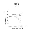
- Fig. 4 shows characteristics of the lubricating oil flow rate through the annular groove, versus the rpm of the output gear 7 when the temperature of the lubricating oil is 120°C.
- a line A of Fig. 4 is a characteristic of a comparative example in which the annular groove is narrow and shallow, and the oil in the annular groove rotates together with the output gear.
- a line B is a characteristic according to the present invention. As evident from Fig. 5, the effect of the present invention is remarkable especially at high speeds.
Landscapes
- Engineering & Computer Science (AREA)
- General Engineering & Computer Science (AREA)
- Mechanical Engineering (AREA)
- General Details Of Gearings (AREA)
- Arrangement Of Transmissions (AREA)
Applications Claiming Priority (2)
| Application Number | Priority Date | Filing Date | Title |
|---|---|---|---|
| JP58190677A JPS6084469A (ja) | 1983-10-14 | 1983-10-14 | 自動変速機の出力歯車部における潤滑装置 |
| JP190677/83 | 1983-10-14 |
Publications (3)
| Publication Number | Publication Date |
|---|---|
| EP0148331A2 true EP0148331A2 (de) | 1985-07-17 |
| EP0148331A3 EP0148331A3 (en) | 1985-09-04 |
| EP0148331B1 EP0148331B1 (de) | 1988-01-20 |
Family
ID=16262044
Family Applications (1)
| Application Number | Title | Priority Date | Filing Date |
|---|---|---|---|
| EP84112155A Expired EP0148331B1 (de) | 1983-10-14 | 1984-10-10 | Abtriebsrad eines automatischen Getriebes |
Country Status (4)
| Country | Link |
|---|---|
| US (1) | US4628754A (de) |
| EP (1) | EP0148331B1 (de) |
| JP (1) | JPS6084469A (de) |
| DE (1) | DE3468923D1 (de) |
Cited By (1)
| Publication number | Priority date | Publication date | Assignee | Title |
|---|---|---|---|---|
| EP2503193A1 (de) * | 2011-03-21 | 2012-09-26 | Deere & Company | Schmiervorrichtung zum Schmieren einer verkeilten Verbindung |
Families Citing this family (11)
| Publication number | Priority date | Publication date | Assignee | Title |
|---|---|---|---|---|
| JPH0536114Y2 (de) * | 1986-07-23 | 1993-09-13 | ||
| JP2825820B2 (ja) * | 1988-08-11 | 1998-11-18 | アイシン・エィ・ダブリュ株式会社 | 自動変速機におけるオイルリザーバ装置 |
| JPH02118258A (ja) * | 1988-10-25 | 1990-05-02 | Nissan Motor Co Ltd | トランスミッションケースの接合部 |
| US5282518A (en) * | 1990-02-14 | 1994-02-01 | Nissan Motor Co., Ltd. | Vehicular four wheel drive train |
| JPH04231770A (ja) * | 1990-12-28 | 1992-08-20 | Nissan Motor Co Ltd | 歯車装置 |
| JP3301546B2 (ja) * | 1992-02-24 | 2002-07-15 | ジヤトコ株式会社 | 自動変速機 |
| US5363723A (en) * | 1993-02-23 | 1994-11-15 | Ryobi Outdoor Products, Inc. | Angle gear drive |
| US5477751A (en) * | 1994-02-17 | 1995-12-26 | Jatco Corporation | Clutch assembly for an automatic transmission |
| JP4747393B2 (ja) * | 2000-03-28 | 2011-08-17 | いすゞ自動車株式会社 | 変速機のオイル経路構造 |
| DE10147853A1 (de) * | 2001-09-27 | 2003-04-10 | Zahnradfabrik Friedrichshafen | Getriebe |
| JP4998185B2 (ja) * | 2007-10-02 | 2012-08-15 | マツダ株式会社 | 自動変速機 |
Family Cites Families (17)
| Publication number | Priority date | Publication date | Assignee | Title |
|---|---|---|---|---|
| US3097546A (en) * | 1963-07-16 | Transmission mechanism | ||
| US3035457A (en) * | 1958-03-31 | 1962-05-22 | Chrysler Corp | Hydrodynamic transmission |
| US2984122A (en) * | 1958-05-27 | 1961-05-16 | Borg Warner | Transmission mechanism |
| US3099927A (en) * | 1960-09-09 | 1963-08-06 | Ford Motor Co | Infinitely variable transmission |
| US3859872A (en) * | 1969-08-25 | 1975-01-14 | Borg Warner | Automotive transmission |
| DE2029515C3 (de) * | 1970-06-13 | 1975-04-24 | Fiat S.P.A., Turin (Italien) | Antriebsblock für Kraftfahrzeuge |
| DE2401542C3 (de) * | 1974-01-14 | 1980-08-21 | Zahnradfabrik Friedrichshafen Ag, 7990 Friedrichshafen | Hydraulischer Regler für automatische Lastschaltgetriebe |
| GB1518092A (en) * | 1974-10-02 | 1978-07-19 | Automotive Prod Co Ltd | Power transmission systems providing automatic changes of gear ratio |
| US4095487A (en) * | 1976-08-11 | 1978-06-20 | Chrysler Corporation | Power transmission driveline unit |
| US4232567A (en) * | 1977-05-20 | 1980-11-11 | Variable Kinetic Drives Limited | Power transmission apparatus |
| JPS54132062A (en) * | 1978-04-04 | 1979-10-13 | Nissan Motor Co Ltd | Lock-up controlling apparatus for lock-up torque converter |
| US4222283A (en) * | 1978-04-27 | 1980-09-16 | General Motors Corporation | Manual transmission lubrication system |
| FR2430543A1 (fr) * | 1978-07-06 | 1980-02-01 | Peugeot | Dispositif de transmission a commande automatique, notamment pour vehicule automobile |
| JPS5852104B2 (ja) * | 1978-09-18 | 1983-11-19 | 日産自動車株式会社 | 前輪駆動車用自動変速機 |
| US4283968A (en) * | 1979-06-25 | 1981-08-18 | Eaton Corporation | Housing assembly for electric vehicle transaxle |
| JPS6112449Y2 (de) * | 1981-02-06 | 1986-04-18 | ||
| US4531421A (en) * | 1983-12-06 | 1985-07-30 | Deere & Company | Transfer case oil pump |
-
1983
- 1983-10-14 JP JP58190677A patent/JPS6084469A/ja active Granted
-
1984
- 1984-10-10 DE DE8484112155T patent/DE3468923D1/de not_active Expired
- 1984-10-10 EP EP84112155A patent/EP0148331B1/de not_active Expired
- 1984-10-12 US US06/660,081 patent/US4628754A/en not_active Expired - Fee Related
Cited By (1)
| Publication number | Priority date | Publication date | Assignee | Title |
|---|---|---|---|---|
| EP2503193A1 (de) * | 2011-03-21 | 2012-09-26 | Deere & Company | Schmiervorrichtung zum Schmieren einer verkeilten Verbindung |
Also Published As
| Publication number | Publication date |
|---|---|
| EP0148331B1 (de) | 1988-01-20 |
| EP0148331A3 (en) | 1985-09-04 |
| DE3468923D1 (en) | 1988-02-25 |
| US4628754A (en) | 1986-12-16 |
| JPS6218783B2 (de) | 1987-04-24 |
| JPS6084469A (ja) | 1985-05-13 |
Similar Documents
| Publication | Publication Date | Title |
|---|---|---|
| US10119576B2 (en) | Optimized outer clutch housing for reduced spin loss, improved oil flow and improved clutch durability | |
| US4498353A (en) | Air breather structure for oil seals in an automatic transmission | |
| CN110566651B (zh) | 扭矩传递装置和具有凹齿侧表面的套环 | |
| EP1959165A2 (de) | Motorantriebsstrang und Verfahren zu seiner Montage | |
| US4628754A (en) | Output gear of automatic transmission | |
| US3762503A (en) | Lubrication system for limited slip differential | |
| US7442143B2 (en) | Drive module for a variable torque distribution | |
| US4759234A (en) | Automatic transmission bearing for supporting axial and radial loads | |
| JPH06211065A (ja) | 改良タンデム駆動車軸 | |
| US9902263B2 (en) | Multi-plate friction clutch having center lubricant feed and lubricant evacuation capabilities | |
| KR100827260B1 (ko) | 자동 변속기 | |
| EP0145462A2 (de) | Keilantrieb für Metallriemengetriebe | |
| US3966020A (en) | Differential lubrication system | |
| US11400803B1 (en) | Vehicle driveline component | |
| US7178424B2 (en) | Pinion unit in axle assembly | |
| US5178027A (en) | Supporting structure for output shaft of automotive automatic power transmission | |
| US5176040A (en) | Transmission for 4-wheel driving | |
| JP2864444B2 (ja) | タンデム式駆動軸の潤滑装置 | |
| JPH06341516A (ja) | 四輪駆動車の動力伝達装置 | |
| WO2020125333A1 (en) | A vehicle powertrain system | |
| JPS6212664Y2 (de) | ||
| JPS5947182B2 (ja) | 自動車用自動変速機の潤滑油供給機構 | |
| KR0174167B1 (ko) | 자동변속기 | |
| JPH0744844Y2 (ja) | ディファレンシャル装置における潤滑機構 | |
| JP2586460B2 (ja) | 動力伝達装置 |
Legal Events
| Date | Code | Title | Description |
|---|---|---|---|
| PUAI | Public reference made under article 153(3) epc to a published international application that has entered the european phase |
Free format text: ORIGINAL CODE: 0009012 |
|
| PUAL | Search report despatched |
Free format text: ORIGINAL CODE: 0009013 |
|
| 17P | Request for examination filed |
Effective date: 19841010 |
|
| AK | Designated contracting states |
Designated state(s): DE FR GB |
|
| AK | Designated contracting states |
Designated state(s): DE FR GB |
|
| 17Q | First examination report despatched |
Effective date: 19860926 |
|
| GRAA | (expected) grant |
Free format text: ORIGINAL CODE: 0009210 |
|
| AK | Designated contracting states |
Kind code of ref document: B1 Designated state(s): DE FR GB |
|
| PG25 | Lapsed in a contracting state [announced via postgrant information from national office to epo] |
Ref country code: FR Free format text: THE PATENT HAS BEEN ANNULLED BY A DECISION OF A NATIONAL AUTHORITY Effective date: 19880120 |
|
| REF | Corresponds to: |
Ref document number: 3468923 Country of ref document: DE Date of ref document: 19880225 |
|
| EN | Fr: translation not filed | ||
| PLBE | No opposition filed within time limit |
Free format text: ORIGINAL CODE: 0009261 |
|
| STAA | Information on the status of an ep patent application or granted ep patent |
Free format text: STATUS: NO OPPOSITION FILED WITHIN TIME LIMIT |
|
| 26N | No opposition filed | ||
| PG25 | Lapsed in a contracting state [announced via postgrant information from national office to epo] |
Ref country code: DE Effective date: 19890701 |
|
| PGFP | Annual fee paid to national office [announced via postgrant information from national office to epo] |
Ref country code: GB Payment date: 19951002 Year of fee payment: 12 |
|
| PG25 | Lapsed in a contracting state [announced via postgrant information from national office to epo] |
Ref country code: GB Effective date: 19961010 |
|
| GBPC | Gb: european patent ceased through non-payment of renewal fee |
Effective date: 19961010 |