EP0147589B1 - Régulateur de pression commandé par force - Google Patents
Régulateur de pression commandé par force Download PDFInfo
- Publication number
- EP0147589B1 EP0147589B1 EP84113564A EP84113564A EP0147589B1 EP 0147589 B1 EP0147589 B1 EP 0147589B1 EP 84113564 A EP84113564 A EP 84113564A EP 84113564 A EP84113564 A EP 84113564A EP 0147589 B1 EP0147589 B1 EP 0147589B1
- Authority
- EP
- European Patent Office
- Prior art keywords
- pressure
- valve
- pressure medium
- valve member
- edge
- Prior art date
- Legal status (The legal status is an assumption and is not a legal conclusion. Google has not performed a legal analysis and makes no representation as to the accuracy of the status listed.)
- Expired
Links
Images

Classifications
-
- B—PERFORMING OPERATIONS; TRANSPORTING
- B60—VEHICLES IN GENERAL
- B60T—VEHICLE BRAKE CONTROL SYSTEMS OR PARTS THEREOF; BRAKE CONTROL SYSTEMS OR PARTS THEREOF, IN GENERAL; ARRANGEMENT OF BRAKING ELEMENTS ON VEHICLES IN GENERAL; PORTABLE DEVICES FOR PREVENTING UNWANTED MOVEMENT OF VEHICLES; VEHICLE MODIFICATIONS TO FACILITATE COOLING OF BRAKES
- B60T15/00—Construction arrangement, or operation of valves incorporated in power brake systems and not covered by groups B60T11/00 or B60T13/00
- B60T15/02—Application and release valves
-
- Y—GENERAL TAGGING OF NEW TECHNOLOGICAL DEVELOPMENTS; GENERAL TAGGING OF CROSS-SECTIONAL TECHNOLOGIES SPANNING OVER SEVERAL SECTIONS OF THE IPC; TECHNICAL SUBJECTS COVERED BY FORMER USPC CROSS-REFERENCE ART COLLECTIONS [XRACs] AND DIGESTS
- Y10—TECHNICAL SUBJECTS COVERED BY FORMER USPC
- Y10T—TECHNICAL SUBJECTS COVERED BY FORMER US CLASSIFICATION
- Y10T137/00—Fluid handling
- Y10T137/2496—Self-proportioning or correlating systems
- Y10T137/2559—Self-controlled branched flow systems
- Y10T137/2574—Bypass or relief controlled by main line fluid condition
- Y10T137/2605—Pressure responsive
- Y10T137/2607—With pressure reducing inlet valve
- Y10T137/261—Relief port through common sensing means
-
- Y—GENERAL TAGGING OF NEW TECHNOLOGICAL DEVELOPMENTS; GENERAL TAGGING OF CROSS-SECTIONAL TECHNOLOGIES SPANNING OVER SEVERAL SECTIONS OF THE IPC; TECHNICAL SUBJECTS COVERED BY FORMER USPC CROSS-REFERENCE ART COLLECTIONS [XRACs] AND DIGESTS
- Y10—TECHNICAL SUBJECTS COVERED BY FORMER USPC
- Y10T—TECHNICAL SUBJECTS COVERED BY FORMER US CLASSIFICATION
- Y10T137/00—Fluid handling
- Y10T137/8593—Systems
- Y10T137/86919—Sequentially closing and opening alternately seating flow controllers
Definitions
- the invention relates to a force-controlled pressure control valve for in particular pneumatic systems according to the preamble of patent claim 1.
- Such a valve is known from DE-A-30 49 110.
- compressed air systems for example, it is used to convert a weak mechanical control signal into a large-volume, proportional working current.
- This control signal can be fed mechanically, electromagnetically or in some other way to the pressure control valve.
- valves In many application examples for such pressure regulating valves, it is required that the actuating forces applied are low and if possible do not have to overcome any frictional forces. Furthermore, an actuating tappet or control piston or actuator which transmits the actuating forces should make the stroke as short as possible, so that the stroke-dependent forces change as little as possible when actuated by an electromagnet. Furthermore, all parts that move and seal in the valve should be frictionless, since frictional forces negatively influence the switching behavior of the valve, since they generate an undesirable hysteresis. In the known valve, however, it is disadvantageous here that the valve member is sealed within a housing inner bore via a sealing ring, which causes a disadvantageously high friction between the sealing ring and the inner bore.
- valve housing For a quick build-up of the working pressure in a consumer, e.g. Compressed air cylinders, the largest possible flow cross-sections are required in the valve housing. The same can apply to the venting process, for which even larger flow cross-sections are required, since venting takes place more slowly than venting, particularly in the lower pressure range.
- the valve known from the prior art has, as an actuator, a plunger or control piston which is actuated mechanically and guided in the valve housing and sealed with friction seals against an underlying working chamber.
- the tappet opens a double-seat valve that connects the storage chamber to the working chamber. This working pressure acts on the ram against the actuating force and creates a balance.
- the double-seat valve closes again, shuts off the storage chamber and prevents the supply air from flowing further into the working chamber.
- the main disadvantage here is the high friction, which adversely affects the control quality and requires the additional return spring.
- control quality depends on the size of the tappet or control piston.
- the control forces can no longer be applied by economically justifiable electromagnets from a certain tappet or control piston size, which greatly limits the applicability of this type of valve.
- valves among the known pressure control valves are the one known as a fine control valve, in which a pressure spring above the control piston can be pretensioned by a handwheel in such a way that the outlet pressure can be changed in an adjustable manner in relation to the constant supply pressure.
- valves are lever-operated manual control valves, as are known from DE-A-2 251 663 or GB-A-1256496 and e.g. find use in hand brakes in motor vehicles.
- a rotary or swivel movement is converted manually into an output pressure proportional to the angle of rotation by means of a control device comparable with the above.
- valves Another type of valve are electromagnetically controlled pressure control valves, in which a spring-loaded control piston is moved by the force of the electromagnet. They require an electromagnet that provides the same possible power delivery via the control path.
- the known valves of this type are complicated in construction and therefore manufacturing and cost-intensive. In addition, they are only on the market up to a nominal diameter of 4 mm, which is the maximum flow diameter. So-called pilot valves are used for larger nominal diameters.
- Electromagnetically controlled directional control valves have no pressure control function and their structure is completely different from that of force-controlled pressure control valves.
- the invention has for its object to provide a force-controlled pressure control valve of the generic type, in which large working cross sections are opened in a simple manner with small actuation forces and short actuation distances.
- the pressure control valve according to the invention should work largely without friction, be made up of a few parts and, in a further embodiment, allow very rapid ventilation of the working chamber with simple means. It should also be so simple in construction that in particular the valve housing can also be injection molded from plastic and mechanical reworking is not necessary.
- the invention advantageously enables that with simple means and with a mini paints resources, using simple and commercially available elastomer parts, an almost friction-free pressure control valve is created that opens large working cross-sections with low actuation forces, in particular without the aid of additional means such as return springs and pilot valve units. Due to the simple construction of the valve housing, it is also possible that it can also be made of plastic by injection molding. Furthermore, the work area is vented very quickly by means of an elastomer disc. It is particularly advantageous that several functions are assigned to the elastomers used.
- the present invention force-controlled pressure control valve between a pressure medium source 9 for an arbitrary, but in particular pneumatic fluid such as a compressed air tank, and a consumer 19, for example, the actuating cylinder of the compressed air brake of a Fahrzeu - ges arranged (Fig. 1, 2, 5, 6).
- the valve housing 1 of the pressure control valve has a pressure medium inlet 8, a first pressure medium outlet 18 to the consumer 19 and a second pressure medium outlet, ie a relief opening to the ambient medium, for example to the ambient air.
- the second pressure medium outlet will be described in detail, for the time being it should only be pointed out that it consists of a radial play between a countersunk bore 30 and an actuator 3 as the first relief opening and, in a further development of the invention, additionally of a second pressure medium outflow opening 15 of the housing 1 can exist (Fig. 5).
- the pressure medium source 9 is connected by the valve to the consumer 19 in order to fill it with pressure fluid, that is to say, for example compressed air, from the pressure medium source 9.
- the consumer 19 is connected to the ambient medium in order to be vented. The valve blocks the pressure medium source 9 in order to prevent its emptying.
- the maximum pressure that can be generated in the consumer 19 by supplying pressure medium from the pressure medium source 9 is the pressure actually prevailing in the pressure medium source 9. Which pressure actually sets in the consumer 19 as the partial pressure of the pressure prevailing in the pressure medium source 9 depends on a force which is forcibly brought into effect as a control signal on the actuator 3 in the direction of the longitudinal axis thereof, for example by means of an electromagnet.
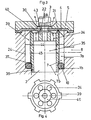
- FIGS. 1 and 2 A simpler embodiment of the pressure control valve according to the invention is shown in FIGS. 1 and 2 in two different operating positions.
- the valve has the valve housing 1 with the pressure medium inlet 8 and the pressure medium outlet 18.
- the pressure medium inlet 8 is connected to the pressure medium source 9 and the pressure medium outlet 18 is connected to the consumer 19.
- the longitudinal axes of pressure medium inlet 8 and pressure medium outlet 18 intersect at an angle of 90 °.
- Pressure medium inlet 8 and pressure medium outlet 18 open into a storage chamber 7, which is arranged axially in line with the pressure medium outlet 18 in the housing 1, is enclosed by a wall 24 and is part of a bore which penetrates the housing from one end to the other, stepped inwards from both sides .
- the storage chamber 7 is closed at the end opposite the pressure medium outlet 18 by a control membrane 4 made of an elastomer, the outside of which rests on a cover 5, which presses the control membrane 4 with its outer edge into an annular groove 23 of the valve housing 1 without play.
- the cover 5 is fixed in the housing 1 in such a position by means of a retaining ring 6 inserted in an annular groove 20 of the housing bore section 21 that the control membrane 4 is held in the groove 23 without play.
- the countersunk bore 30 is arranged in the cover 5 in the same axis as the storage chamber 7, and a bore 22 is also arranged in the control membrane 4 in the same axis as the storage chamber 7.
- the space enclosed by the locking ring 6 is significantly larger than the cross section of the cylindrical storage chamber 7, the cross section of the bore 22 of the control membrane 4 is significantly smaller than the cross section of the storage chamber 7, the smaller cross section of the Bore 30 faces the bore 22 and is larger than the cross section of the bore 22, the larger cross section of the bore 30 is facing the locking ring 6 and smaller than the free space surrounded by it.
- the bores penetrating the housing 1 are stepped from both ends in such a way that the diameters of the individual bore sections decrease, which facilitates the manufacture of the housing.
- the valve member 2 is arranged, which is essentially a cylindrical sleeve which is closed at the upper end with a cover 40 and is provided on the outer circumference with lugs 39 distributed uniformly thereon, with which the valve member 2 is radial, without play but axially is adjustable in the cylindrical storage chamber 7.
- the cover 40 has a number of axial bores 34 near its outer edge, evenly distributed over the circumference, and a further axial bore centrally.
- the valve member 2 is constricted, and in the region of this constriction 36, the valve member 2 is supported by an elastically resilient ring 10 on a collar 1 b surrounding the storage chamber 7.
- the transition 37 to the constricted section 36 of the cylinder wall of the valve member is conical, the angle of this cone having to be greater than the angle of friction between the material of the ring 10 and the material of the housing 1 in order to avoid jamming of the valve member.
- the cover 40 of the valve member and the upper edge of the cylindrical sleeve edge are contoured in such a way that it results in particular from FIG. 3. In the operating position of the valve according to the invention shown in FIGS. 1 and 3, the valve member lies with its upper rounded edge 31 as a sealing surface on the underside of the control membrane 4.
- the pressure medium inlet 8 is connected to the part 7a of the storage chamber 7 lying above the ring 10, but this part 7a is blocked off from the pressure medium outlet 18 by the ring 10 and the abutment of the valve member 2 with its edge 31 on the underside of the control membrane 4.
- the pressure medium outlet 18 is connected via the part 7b of the storage chamber 7 located below the ring 1 to the interior 35 of the valve member 2, which via the axial bores 34, the central bore, the bore 22 of the control membrane 4 and the annular gap between the control piston 3 and the bore 30 communicates with the surroundings of the valve.
- the operating position of the valve shown in FIGS. 1 and 3 is shown as the operating position in which the consumer 19 is vented. According to the arrows in FIGS. 1 and 3, fluid enclosed in the consumer 19 can escape from the consumer 19 via the valve.
- the pressure medium source 9 is separated from the consumer 19.
- a control force directed against the valve (arrow B, FIG. 3) is applied to the actuator 3, the size of which is selected according to the pressure desired in the consumer 19.
- This control force moves the actuator 3 into the valve until it comes into contact with its inner rounded edge 43 as a sealing edge on the inner, free edge area of the control membrane 4 and deforms it inward during further adjustment.
- the initially present axial play between the control membrane and the inner collar of the cover 40 is overcome and with the still further adjustment movement of the actuator 3, the valve member 2 is adjusted inwards so that its edge 31 detaches from the control membrane 4 .
- the control force acts on a small circumference and the pressure fluid flows over a large circumference into the interior 35 of the valve member.
- the limitation of the pressure in the interior 35 and in the consumer 19 is due to the fact that when fluid flows from the pressure medium source into the interior 35, this acts not only in the consumer 19, but through the central opening of the cover 40 and the axis-parallel opening 22 of the Control membrane 4 directly counteracts the underside of the actuator 3 and thus the control force B.
- the diameter 44 of the edge 31 of the valve member 2 acting as a valve seat should be equal to the diameter 45 of the line of interaction between the ring 10 and the transition cone 37 of the valve member 2. If the diameters 44 and 45 are of equal size according to the invention, the valve member 2 is held in contact with the control membrane 4 with its edge 31 in the state of equilibrium between the pressure inside and outside the valve member by the prestressing of the ring 10 with its edge 31.
- the construction and operation of the valve according to the invention is very simple and reliable. It uses only simple, low-wear components, it is reliable and can be manufactured with a low use of materials and hours. Likewise, an acceptable use of machinery will be necessary.
- a small control force is required to adjust the valve, which is used on short control paths.
- the control force is applied via the actuator 3, the flow cross-section in the area of line 31 is released on a large scale in view of the size of the valve, so that after reaching the ventilation position and because of the short flow paths in the valve, the consumer 19 in extreme ventilated for a short time, d. H. is filled with pressurized fluid.
- the valve works largely free of frictional forces, so that it not only works with low wear, but also precisely and with little delay.
- valve according to FIGS. 1 to 4 will optimally meet the requirements, as can be seen in particular from the above statements.
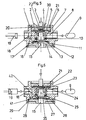
- pressure medium inlet 8 and pressure medium outlet 18 are coaxial so that their longitudinal axes intersect the longitudinal axis of the storage chamber 7.
- a further pressure medium outflow opening 15 is provided at the other end of housing 1, the cross section of which at least approximately corresponds to the cross section of pressure medium inlet 8 and pressure medium outlet 18.
- the second pressure medium outflow opening is surrounded by a collar 42, which has a relatively large surface perpendicular to the longitudinal axis of the storage chamber 7.
- a vent disk 13 is in turn made of an elastomer. The breather disc is naturally flat, but it deforms under the flow pressure of the fluid.
- This disc 13 is adjustable between the collar 42 and the edge 27 opposite this collar 42 at the inner end of the storage chamber 7 in the longitudinal direction of the chamber 7. If the consumer 19 is to be ventilated in the manner described above, the pressure in the interior of the valve member 35 applies the disc 13 to the collar 42 and pressurized fluid passes through a working chamber 16 into the pressure medium outlet 18 (FIG. 6). If the control force on the actuator 3 is reduced in order to vent the consumer 19 in the manner described above, and then the pressure in the valve member interior 35 falls below the pressure in the pressure medium outlet 18 due to pressure fluid which escapes from the valve member interior through the annular gap between the actuator 3 and the bore wall 30.
- the collar 42 is part of a base 14 which closes the valve housing 1 at one end, encloses the pressure medium outflow opening 15 and which is held between a retaining ring 12 and a collar of the housing by inserting a sealing cord 11.
- the storage chamber 7 with the sections 7a, 7b is part of a bore which penetrates the housing 1 in the vertical direction in the drawing and is gradually smaller in cross section from both outer ends, which has the advantage that the production is simple and inexpensive is possible and, if necessary, a simple form of production can be used.
Landscapes
- Engineering & Computer Science (AREA)
- Transportation (AREA)
- Mechanical Engineering (AREA)
- Safety Valves (AREA)
- Control Of Fluid Pressure (AREA)
- Steering Control In Accordance With Driving Conditions (AREA)
- Fluid-Driven Valves (AREA)
- Fluid-Pressure Circuits (AREA)
Claims (17)
Priority Applications (1)
| Application Number | Priority Date | Filing Date | Title |
|---|---|---|---|
| AT84113564T ATE39555T1 (de) | 1983-11-09 | 1984-11-09 | Kraftgesteuertes druckregelventil. |
Applications Claiming Priority (2)
| Application Number | Priority Date | Filing Date | Title |
|---|---|---|---|
| DE19833340525 DE3340525A1 (de) | 1983-11-09 | 1983-11-09 | Kraftgesteuertes druckregelventil |
| DE3340525 | 1983-11-09 |
Publications (3)
| Publication Number | Publication Date |
|---|---|
| EP0147589A2 EP0147589A2 (fr) | 1985-07-10 |
| EP0147589A3 EP0147589A3 (en) | 1986-03-12 |
| EP0147589B1 true EP0147589B1 (fr) | 1988-12-28 |
Family
ID=6213874
Family Applications (1)
| Application Number | Title | Priority Date | Filing Date |
|---|---|---|---|
| EP84113564A Expired EP0147589B1 (fr) | 1983-11-09 | 1984-11-09 | Régulateur de pression commandé par force |
Country Status (4)
| Country | Link |
|---|---|
| US (1) | US4625750A (fr) |
| EP (1) | EP0147589B1 (fr) |
| AT (1) | ATE39555T1 (fr) |
| DE (2) | DE3340525A1 (fr) |
Families Citing this family (9)
| Publication number | Priority date | Publication date | Assignee | Title |
|---|---|---|---|---|
| EP0200802B1 (fr) * | 1985-05-08 | 1989-08-02 | Joachim Dipl.-Ing. Scholz | Vanne électrique |
| DE3734105A1 (de) * | 1987-10-09 | 1989-04-27 | Voss Armaturen | Kraftgesteuertes druckregelventil mit geteiltem ventilglied |
| DE3912042A1 (de) * | 1988-04-12 | 1990-01-11 | Scholz Joachim | Elektromagnet |
| DE9217022U1 (fr) * | 1992-12-15 | 1993-04-01 | Knocks, Heinz, 4714 Selm, De | |
| US5590525A (en) * | 1993-06-01 | 1997-01-07 | Sundstrand Corporation | Method of preventing cavitation in an axial piston pump during an aiding load and system and valve employing the same |
| GB9320347D0 (en) * | 1993-10-02 | 1993-11-24 | Delta Eng Holdings Ltd | Control valve |
| GB2287303A (en) * | 1993-10-02 | 1995-09-13 | Delta Eng Holdings Ltd | Control valve |
| DE59610097D1 (de) * | 1995-10-27 | 2003-03-06 | Oce Printing Systems Gmbh | Einrichtung zum regeln des drucks in einer druckkammer |
| US20040107990A1 (en) | 2002-12-06 | 2004-06-10 | Thanh Ho | Enhanced exhaust flow control feature |
Family Cites Families (15)
| Publication number | Priority date | Publication date | Assignee | Title |
|---|---|---|---|---|
| US2955616A (en) * | 1954-04-29 | 1960-10-11 | Saunders Valve Co Ltd | Fluid controlling diaphragm valves |
| DE1127237B (de) * | 1956-07-14 | 1962-04-05 | Bosch Gmbh Robert | Ventil fuer Druckluftbremsanlagen in Kraftfahrzeugen |
| US2985490A (en) * | 1959-10-05 | 1961-05-23 | Bendix Westinghouse Automotive | Fluid pressure valve |
| US3328092A (en) * | 1965-12-22 | 1967-06-27 | Wagner Electric Corp | Dual self-lapping control valve |
| AT264308B (de) * | 1966-08-12 | 1968-08-26 | Hardy Geb Maschf Ag | Druckregler |
| GB1256496A (fr) * | 1968-04-29 | 1971-12-08 | ||
| US3578024A (en) * | 1968-10-31 | 1971-05-11 | Jennings Paul Hill | Supply and exhaust control valve |
| GB1349020A (en) * | 1971-10-21 | 1974-03-27 | Dewandre Co Ltd C | Hand control valves for use in vehicle braking systems |
| DE2306390A1 (de) * | 1973-02-09 | 1974-08-22 | Junkers & Co | Membranventil |
| US3862782A (en) * | 1973-07-27 | 1975-01-28 | Berg Manufacturing Co | Spring brake chamber control valve |
| DE2551997A1 (de) * | 1975-11-20 | 1977-06-02 | Knorr Bremse Gmbh | Einstellbares druckuebersetzungs- bzw. -untersetzungsventil |
| DE2832076A1 (de) * | 1978-07-21 | 1980-01-31 | Bosch Gmbh Robert | Druckregler |
| DE3006587A1 (de) * | 1980-02-22 | 1981-09-10 | Robert Bosch Gmbh, 7000 Stuttgart | Membrandruckregler |
| DE3038797A1 (de) * | 1980-10-14 | 1982-05-27 | Herion-Werke Kg, 7012 Fellbach | Druckregelventil |
| DE3049110C2 (de) * | 1980-12-24 | 1983-04-28 | Festo-Maschinenfabrik Gottlieb Stoll, 7300 Esslingen | Pneumatisches Dreiwege-Ventil |
-
1983
- 1983-11-09 DE DE19833340525 patent/DE3340525A1/de not_active Withdrawn
-
1984
- 1984-11-09 DE DE8484113564T patent/DE3475823D1/de not_active Expired
- 1984-11-09 AT AT84113564T patent/ATE39555T1/de not_active IP Right Cessation
- 1984-11-09 EP EP84113564A patent/EP0147589B1/fr not_active Expired
-
1985
- 1985-05-09 US US06/732,785 patent/US4625750A/en not_active Expired - Fee Related
Also Published As
| Publication number | Publication date |
|---|---|
| DE3340525A1 (de) | 1985-05-15 |
| EP0147589A3 (en) | 1986-03-12 |
| ATE39555T1 (de) | 1989-01-15 |
| US4625750A (en) | 1986-12-02 |
| EP0147589A2 (fr) | 1985-07-10 |
| DE3475823D1 (en) | 1989-02-02 |
Similar Documents
| Publication | Publication Date | Title |
|---|---|---|
| EP0578168B1 (fr) | Valve | |
| DE2149915A1 (de) | Proportionalstroemungsregler | |
| DE2044894C3 (de) | Zweikreis-Bremsventil für Druckluftbremsanlagen | |
| CH691877A5 (de) | Vakuumdruck-Kontrollventil für verlangsamte Absaugung. | |
| CH654888A5 (de) | Druckregelventilaggregat. | |
| CH695298A5 (de) | Turbulenzfreies Entlueftungsventil. | |
| DE3305092C2 (fr) | ||
| DE3722315C2 (fr) | ||
| EP0147589B1 (fr) | Régulateur de pression commandé par force | |
| EP0380754A2 (fr) | Soupape de levage à force équilibrée | |
| DE602004005533T2 (de) | Elektropneumatischer Luftdruckregler | |
| DE2405799A1 (de) | Tellerventil | |
| EP0223935B1 (fr) | Valve de commande de pression de freinage commandés par deux circuits | |
| DE2910764A1 (de) | Ventil | |
| DE3544177C2 (fr) | ||
| EP0289712B1 (fr) | Régulateur de pression | |
| DE4201442A1 (de) | Elektronisch geregeltes direkt betätigtes 3-Wege-Druckregelventil für gasförmige und flüssige Medien | |
| DE19626323B4 (de) | Sicherheitsventileinrichtung | |
| DE3509183C1 (de) | Selbstschlussarmatur | |
| DE2317312C2 (de) | Drucksteuerventil, insbesondere Bremsventil | |
| DE102014016701A1 (de) | Steuerbares Rückschlagventil | |
| DE3827013A1 (de) | Druckregelventil | |
| DE3639149C2 (de) | Lastabhängig steuerbare Bremskraftregeleinrichtung | |
| DE4244292C2 (de) | 3/2-Wegeventil | |
| DE102004001370B3 (de) | Kombiniertes Druckregel-Schaltventil |
Legal Events
| Date | Code | Title | Description |
|---|---|---|---|
| PUAI | Public reference made under article 153(3) epc to a published international application that has entered the european phase |
Free format text: ORIGINAL CODE: 0009012 |
|
| AK | Designated contracting states |
Designated state(s): AT BE CH DE FR GB IT LI LU NL SE |
|
| PUAL | Search report despatched |
Free format text: ORIGINAL CODE: 0009013 |
|
| AK | Designated contracting states |
Kind code of ref document: A3 Designated state(s): AT BE CH DE FR GB IT LI LU NL SE |
|
| 17P | Request for examination filed |
Effective date: 19860110 |
|
| 17Q | First examination report despatched |
Effective date: 19870819 |
|
| GRAA | (expected) grant |
Free format text: ORIGINAL CODE: 0009210 |
|
| AK | Designated contracting states |
Kind code of ref document: B1 Designated state(s): AT BE CH DE FR GB IT LI LU NL SE |
|
| REF | Corresponds to: |
Ref document number: 39555 Country of ref document: AT Date of ref document: 19890115 Kind code of ref document: T |
|
| ITF | It: translation for a ep patent filed |
Owner name: ING. A. GIAMBROCONO & C. S.R.L. |
|
| GBT | Gb: translation of ep patent filed (gb section 77(6)(a)/1977) | ||
| REF | Corresponds to: |
Ref document number: 3475823 Country of ref document: DE Date of ref document: 19890202 |
|
| ET | Fr: translation filed | ||
| PLBE | No opposition filed within time limit |
Free format text: ORIGINAL CODE: 0009261 |
|
| STAA | Information on the status of an ep patent application or granted ep patent |
Free format text: STATUS: NO OPPOSITION FILED WITHIN TIME LIMIT |
|
| 26N | No opposition filed | ||
| ITTA | It: last paid annual fee | ||
| PGFP | Annual fee paid to national office [announced via postgrant information from national office to epo] |
Ref country code: GB Payment date: 19911108 Year of fee payment: 8 |
|
| PGFP | Annual fee paid to national office [announced via postgrant information from national office to epo] |
Ref country code: NL Payment date: 19911130 Year of fee payment: 8 |
|
| PGFP | Annual fee paid to national office [announced via postgrant information from national office to epo] |
Ref country code: DE Payment date: 19920215 Year of fee payment: 8 |
|
| PGFP | Annual fee paid to national office [announced via postgrant information from national office to epo] |
Ref country code: CH Payment date: 19920226 Year of fee payment: 8 Ref country code: BE Payment date: 19920226 Year of fee payment: 8 |
|
| PGFP | Annual fee paid to national office [announced via postgrant information from national office to epo] |
Ref country code: LU Payment date: 19920228 Year of fee payment: 8 |
|
| PGFP | Annual fee paid to national office [announced via postgrant information from national office to epo] |
Ref country code: SE Payment date: 19920306 Year of fee payment: 8 |
|
| PGFP | Annual fee paid to national office [announced via postgrant information from national office to epo] |
Ref country code: FR Payment date: 19920312 Year of fee payment: 8 |
|
| PGFP | Annual fee paid to national office [announced via postgrant information from national office to epo] |
Ref country code: AT Payment date: 19920320 Year of fee payment: 8 |
|
| EPTA | Lu: last paid annual fee | ||
| PG25 | Lapsed in a contracting state [announced via postgrant information from national office to epo] |
Ref country code: LU Free format text: LAPSE BECAUSE OF NON-PAYMENT OF DUE FEES Effective date: 19921109 Ref country code: GB Effective date: 19921109 Ref country code: AT Effective date: 19921109 |
|
| PG25 | Lapsed in a contracting state [announced via postgrant information from national office to epo] |
Ref country code: SE Effective date: 19921110 |
|
| PG25 | Lapsed in a contracting state [announced via postgrant information from national office to epo] |
Ref country code: LI Effective date: 19921130 Ref country code: CH Effective date: 19921130 Ref country code: BE Effective date: 19921130 |
|
| BERE | Be: lapsed |
Owner name: SCHOLZ JOACHIM Effective date: 19921130 |
|
| PG25 | Lapsed in a contracting state [announced via postgrant information from national office to epo] |
Ref country code: NL Effective date: 19930601 |
|
| GBPC | Gb: european patent ceased through non-payment of renewal fee |
Effective date: 19921109 |
|
| NLV4 | Nl: lapsed or anulled due to non-payment of the annual fee | ||
| PG25 | Lapsed in a contracting state [announced via postgrant information from national office to epo] |
Ref country code: FR Effective date: 19930730 |
|
| REG | Reference to a national code |
Ref country code: CH Ref legal event code: PL |
|
| PG25 | Lapsed in a contracting state [announced via postgrant information from national office to epo] |
Ref country code: DE Effective date: 19930803 |
|
| REG | Reference to a national code |
Ref country code: FR Ref legal event code: ST |
|
| EUG | Se: european patent has lapsed |
Ref document number: 84113564.3 Effective date: 19930610 |