EP0200802B1 - Vanne électrique - Google Patents
Vanne électrique Download PDFInfo
- Publication number
- EP0200802B1 EP0200802B1 EP85105643A EP85105643A EP0200802B1 EP 0200802 B1 EP0200802 B1 EP 0200802B1 EP 85105643 A EP85105643 A EP 85105643A EP 85105643 A EP85105643 A EP 85105643A EP 0200802 B1 EP0200802 B1 EP 0200802B1
- Authority
- EP
- European Patent Office
- Prior art keywords
- membrane
- valve member
- control piston
- edge
- valve
- Prior art date
- Legal status (The legal status is an assumption and is not a legal conclusion. Google has not performed a legal analysis and makes no representation as to the accuracy of the status listed.)
- Expired
Links
Images
Classifications
-
- G—PHYSICS
- G05—CONTROLLING; REGULATING
- G05D—SYSTEMS FOR CONTROLLING OR REGULATING NON-ELECTRIC VARIABLES
- G05D16/00—Control of fluid pressure
- G05D16/04—Control of fluid pressure without auxiliary power
- G05D16/06—Control of fluid pressure without auxiliary power the sensing element being a flexible membrane, yielding to pressure, e.g. diaphragm, bellows, capsule
- G05D16/063—Control of fluid pressure without auxiliary power the sensing element being a flexible membrane, yielding to pressure, e.g. diaphragm, bellows, capsule the sensing element being a membrane
- G05D16/0638—Control of fluid pressure without auxiliary power the sensing element being a flexible membrane, yielding to pressure, e.g. diaphragm, bellows, capsule the sensing element being a membrane characterised by the form of the obturator
- G05D16/0641—Control of fluid pressure without auxiliary power the sensing element being a flexible membrane, yielding to pressure, e.g. diaphragm, bellows, capsule the sensing element being a membrane characterised by the form of the obturator the obturator is a membrane
-
- G—PHYSICS
- G05—CONTROLLING; REGULATING
- G05D—SYSTEMS FOR CONTROLLING OR REGULATING NON-ELECTRIC VARIABLES
- G05D16/00—Control of fluid pressure
- G05D16/20—Control of fluid pressure characterised by the use of electric means
- G05D16/2086—Control of fluid pressure characterised by the use of electric means without direct action of electric energy on the controlling means
-
- Y—GENERAL TAGGING OF NEW TECHNOLOGICAL DEVELOPMENTS; GENERAL TAGGING OF CROSS-SECTIONAL TECHNOLOGIES SPANNING OVER SEVERAL SECTIONS OF THE IPC; TECHNICAL SUBJECTS COVERED BY FORMER USPC CROSS-REFERENCE ART COLLECTIONS [XRACs] AND DIGESTS
- Y10—TECHNICAL SUBJECTS COVERED BY FORMER USPC
- Y10T—TECHNICAL SUBJECTS COVERED BY FORMER US CLASSIFICATION
- Y10T137/00—Fluid handling
- Y10T137/2496—Self-proportioning or correlating systems
- Y10T137/2559—Self-controlled branched flow systems
- Y10T137/2574—Bypass or relief controlled by main line fluid condition
- Y10T137/2605—Pressure responsive
- Y10T137/2607—With pressure reducing inlet valve
- Y10T137/261—Relief port through common sensing means
-
- Y—GENERAL TAGGING OF NEW TECHNOLOGICAL DEVELOPMENTS; GENERAL TAGGING OF CROSS-SECTIONAL TECHNOLOGIES SPANNING OVER SEVERAL SECTIONS OF THE IPC; TECHNICAL SUBJECTS COVERED BY FORMER USPC CROSS-REFERENCE ART COLLECTIONS [XRACs] AND DIGESTS
- Y10—TECHNICAL SUBJECTS COVERED BY FORMER USPC
- Y10T—TECHNICAL SUBJECTS COVERED BY FORMER US CLASSIFICATION
- Y10T137/00—Fluid handling
- Y10T137/8593—Systems
- Y10T137/86919—Sequentially closing and opening alternately seating flow controllers
Definitions
- the invention relates to a force-controlled pressure control valve or electrically controllable valve.
- the valve not only acts as a digital open-close control to vent the consumer (connection to the fluid discharge) or to allow a pressure corresponding to the pressure in the fluid source to prevail in it (connection to the fluid source), but rather the valve allows the setting of any pressure in the consumer up to the pressure in the fluid source as the maximum pressure in an analogous manner, solely by measuring the external force acting on the control piston.
- the pressure determined by the external force applied to the control piston arises from the fact that a state of equilibrium is established between the venting and venting state, in that the pressure in the interior of the valve member corresponds to the counteracting force and counteracts it.
- a state of equilibrium is established between the venting and venting state, in that the pressure in the interior of the valve member corresponds to the counteracting force and counteracts it.
- a ring of holes is provided in the cover of the valve member, through which the connection between the fluid source and the consumer is made when the consumer is ventilated, the connection between the consumer and the vent is made when the consumer is vented, and it is in the state of equilibrium Fluid in the interior of the valve member is enabled to bring the back pressure to the external force.
- This solution requires a relatively fine adjustment of the distance between the cover of the valve member and the underside of the membrane, which can be undesirable for various reasons.
- the object of the invention is to further develop the already proposed solution so that the fluid pressure in the interior of the valve member during the equilibrium state can be brought into effect with simple means and reliably against the external force acting on the control piston.
- a central opening in the cover of the valve member within the perforated rim provided there and mentioned above is to be used, which is already provided in the older solution, but without it being recognizably assigned a specific function. Accordingly, it is proposed with the present invention that a central opening enclosed by the abutment is so large that its cross section together with the cross section of the flow channel between the abutment and the second edge of the valve member corresponds approximately to the cross section of the flow channel between the control piston and the outer wall of the flow channel.
- the invention enables a further expedient embodiment of the invention in such a way that a stop for the springing back of the membrane can be arranged particularly expediently in a manner to be described.
- a stop for the springing back of the membrane can be arranged particularly expediently in a manner to be described.
- the cover of the valve body is arranged as a stop when the membrane is deformed in one direction on one side of the membrane, this stop should be arranged on the other side of the membrane, but should be held on the cover.
- the stop is a radial flange at one end of a sleeve which is held in the central opening designed according to the invention.
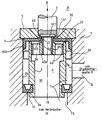
- valve according to the invention is shown as a central longitudinal section.
- the force-controlled pressure control valve is arranged between a pressure medium source 9 for any, but in particular pneumatic, fluid, for example a compressed air tank and a consumer 19, for example the actuating cylinder of the compressed air brake of a vehicle.
- the valve housing 1 of the pressure control valve has a pressure medium inlet 8, a first pressure medium outlet 18 to the consumer 19 and a second pressure medium outlet to the ambient medium, for example to the ambient air.
- the second pressure medium outlet essentially consists of the radial play between a countersunk bore 30 and a control piston 3.
- the pressure medium source 9 is connected through the valve to the consumer 19 in order to fill the consumer with pressure fluid, that is to say, for example compressed air, from the pressure medium source 9.
- the consumer 19 is connected to the ambient medium in order to be vented. The valve blocks the pressure medium source 9 in order to prevent its emptying.
- the maximum pressure that can be generated in the consumer 19 by supplying pressure medium from the pressure medium source 9 is the pressure actually prevailing in the pressure medium source 9. Which pressure actually sets in the consumer 19 as the partial pressure of the pressure prevailing in the pressure medium source 9 depends on a force B which is forcibly brought into effect as a control signal on the control piston 3 in the direction of its longitudinal axis, for example by means of an electromagnet.
- pressure medium inlet 8 and pressure medium outlet 18 intersect at an angle of 90 °.
- Pressure medium inlet 8 and pressure medium outlet 18 open into a storage chamber 7, which is arranged coaxially with the pressure medium outlet 18 in the housing 1, is enclosed by a wall 24 of the housing 1 and is part of a bore which the housing 1 from one end to the other, from both sides graded inward, penetrating.
- the storage chamber 7 is closed at the end opposite the pressure medium outlet 18 by a control membrane 4 made of an elastomer, the larger part of which lies on the outside of a cover 5 of the housing 1.
- the cover 5 is fixed to the housing 1 by means of screws (not shown).
- the countersunk bore 30 is arranged in the cover 5 in the same axis as the storage chamber 7, and a bore 22 is also arranged in the control membrane 4 in the same axis as the storage chamber 7.
- the space adjoining the bore 30 is significantly larger than the cross section of the cylindrical storage chamber 7, the cross section of the bore 22 of the control membrane 4 is significantly smaller than the cross section of the storage chamber 7; the smaller cross section of the bore 30 faces the bore 22 and is larger than the cross section of the bore 22, the larger cross section of the bore 30 faces the larger space A (area around the valve) adjoining the bore.
- the valve member 2 is arranged, which is essentially a cylindrical sleeve, which is closed at the upper end with a cover 40 and is provided on the outer circumference with evenly distributed on deisen lugs 39, with which the valve member 2 radially without play but axially is adjustable in the cylindrical storage chamber 7.
- the cover 40 has a central body (40a) and, close to its outer edge, has a number of axial bores 34 and a further axial bore 100 centrally distributed over the circumference.
- the valve member 2 has an annular groove, into which a cross-sectionally U-shaped ring 10 is inserted, which consists of elastically resilient material and via which the valve member 2 is supported on a step of the wall 24.
- the valve member lies with its upper rounded edge 31 as a sealing surface on the underside of the control membrane 4.
- the pressure medium inlet 8 is connected to the part 7a of the storage chamber 7 lying above the ring 10, but this part 7a is blocked off from the pressure medium outlet 18 by the ring 10 and the abutment of the valve member 2 with its edge 31 on the underside of the control membrane 4.
- the pressure medium outlet 18 is connected via the part 7b of the storage chamber 7 lying under the ring 10 to the interior 35 of the valve member 2, which via the axial bores 34, the central bore 100, the bore 22 of the control membrane 4 and the annular gap 101 between the Control piston 3 and the bore 30 communicates with the surroundings of the valve.
- the operating position of the valve shown is thus shown as the operating position in which the consumer 19 is vented. Fluid enclosed in the consumer 19 can escape from the consumer 19 via the valve. The pressure medium source 9 is separated from the consumer 19.
- the consumer 19 If the consumer 19 is to be ventilated, it must instead be connected to the pressure medium source 9.
- a control force directed against the valve is applied to the control piston 3, the size of which is selected according to the pressure desired in the consumer 19.
- This control force adjusts the control piston 3 into the valve until it comes into contact with its inner rounded edge 43 as a sealing edge on the inner, free edge area of the control diaphragm 4 and deforms it inward during further adjustment.
- the further adjustment movement of the control piston this is the case at first Axial play between the control membrane and the inner collar of the cover 40 is overcome and during the still further adjustment movement of the control piston 3, the valve member 2 is adjusted inwards so that its edge 31 detaches from the control membrane 4.
- the cross section of the bore 100 should preferably correspond at least approximately to the cross section of the annular gap 101, so that a throttle-free outflow of the fluid from the consumer is possible solely through the bore 100.
- a sleeve 102 is inserted into the axial bore 100 of the central body of the cover 40, which surrounds the bore 100 and whose upper side lies according to the invention below the upper edge 31, the upper end of which is used as a radial flange 103 for limitation the springback of the diaphragm 4 is formed when the control piston 3 goes up.
- the free cross section of the sleeve 102 is dimensioned such that it corresponds at least approximately to the cross section of the annular gap 101, so the bore 100 must be correspondingly larger.
- the sleeve 102 is passed through the bore 22 of the diaphragm 4 and the radial flange 103 lies above the diaphragm 4.
- the diaphragm 4 lifts up from the underside of the radial flange 103 until it opens the top of the central body of the cover 40 comes to rest and to lift the edge 31 from the membrane 4 of the control piston 3 over the inner edge of the membrane and the central body of the cover 40 the valve member 2 inwards (with respect to the valve) or downwards (with respect to the image plane). If the pressure in the interior 35 of the valve member 2 now outweighs the force B such that the control piston 3 moves upward, the relaxing membrane 4 can follow the control piston 3 in the region of the inner edge until it abuts against the radial flange 103 is coming.
- the radial flange 103 is not provided as a stop acting in this way, it can only be prevented by careful selection of the material of the diaphragm 4 that it follows the control piston 3 beyond the illustrated venting position and in turn closes or impairs the annular gap 101.
- the material of the diaphragm can be selected without having to pay attention to this problem.
- the dimensioning of the bore 100 according to the invention is advantageous without the insert 102, but is particularly advantageous when the insert is used in order to enable ventilation.
Landscapes
- Physics & Mathematics (AREA)
- Fluid Mechanics (AREA)
- General Physics & Mathematics (AREA)
- Engineering & Computer Science (AREA)
- Automation & Control Theory (AREA)
- Safety Valves (AREA)
- Control Of Fluid Pressure (AREA)
- Fluid-Driven Valves (AREA)
Claims (6)
Priority Applications (3)
| Application Number | Priority Date | Filing Date | Title |
|---|---|---|---|
| DE8585105643T DE3572052D1 (en) | 1985-05-08 | 1985-05-08 | Electric valve |
| EP85105643A EP0200802B1 (fr) | 1985-05-08 | 1985-05-08 | Vanne électrique |
| US06/860,509 US4699167A (en) | 1985-05-08 | 1986-05-07 | Electric valve |
Applications Claiming Priority (1)
| Application Number | Priority Date | Filing Date | Title |
|---|---|---|---|
| EP85105643A EP0200802B1 (fr) | 1985-05-08 | 1985-05-08 | Vanne électrique |
Publications (2)
| Publication Number | Publication Date |
|---|---|
| EP0200802A1 EP0200802A1 (fr) | 1986-11-12 |
| EP0200802B1 true EP0200802B1 (fr) | 1989-08-02 |
Family
ID=8193487
Family Applications (1)
| Application Number | Title | Priority Date | Filing Date |
|---|---|---|---|
| EP85105643A Expired EP0200802B1 (fr) | 1985-05-08 | 1985-05-08 | Vanne électrique |
Country Status (3)
| Country | Link |
|---|---|
| US (1) | US4699167A (fr) |
| EP (1) | EP0200802B1 (fr) |
| DE (1) | DE3572052D1 (fr) |
Family Cites Families (5)
| Publication number | Priority date | Publication date | Assignee | Title |
|---|---|---|---|---|
| DE1258166B (de) * | 1964-07-17 | 1968-01-04 | Ranco Inc | Unterdruckregler |
| US3578024A (en) * | 1968-10-31 | 1971-05-11 | Jennings Paul Hill | Supply and exhaust control valve |
| DE3049110C2 (de) * | 1980-12-24 | 1983-04-28 | Festo-Maschinenfabrik Gottlieb Stoll, 7300 Esslingen | Pneumatisches Dreiwege-Ventil |
| DE8121663U1 (de) * | 1981-07-23 | 1981-11-26 | Kraftwerk Union AG, 4330 Mülheim | Elektrohydraulischer stellantrieb fuer ventile |
| DE3340525A1 (de) * | 1983-11-09 | 1985-05-15 | Joachim Dipl.-Ing. 7551 Bischweier Scholz | Kraftgesteuertes druckregelventil |
-
1985
- 1985-05-08 DE DE8585105643T patent/DE3572052D1/de not_active Expired
- 1985-05-08 EP EP85105643A patent/EP0200802B1/fr not_active Expired
-
1986
- 1986-05-07 US US06/860,509 patent/US4699167A/en not_active Expired - Fee Related
Also Published As
| Publication number | Publication date |
|---|---|
| DE3572052D1 (en) | 1989-09-07 |
| EP0200802A1 (fr) | 1986-11-12 |
| US4699167A (en) | 1987-10-13 |
Similar Documents
| Publication | Publication Date | Title |
|---|---|---|
| EP0726511B1 (fr) | Vanne de régulation de pression | |
| DE69208435T2 (de) | Druckflüssigkeitszylinder mit Druckübersetzer | |
| DE4409252A1 (de) | Luftfederungsanlage | |
| DE69612535T2 (de) | Vorgesteuertes Fluidumventil | |
| DE69910766T2 (de) | Gasventil und verfahren zur erzeugung eines druckstosses | |
| DE2113011A1 (de) | Druckluftregler fuer eine Anzahl von Druckwerten | |
| DE2010969B2 (de) | Druckluft-bremseinrichtung | |
| DE2002520C3 (de) | Fluidischer Membranverstärker | |
| EP0223935B1 (fr) | Valve de commande de pression de freinage commandés par deux circuits | |
| DE2513013B2 (de) | Hydraulisches Wegeventil | |
| EP0147589B1 (fr) | Régulateur de pression commandé par force | |
| DE3722306C2 (fr) | ||
| EP1176347B1 (fr) | Dispositif de commande manuelle pour actionner des soupapes | |
| EP0200802B1 (fr) | Vanne électrique | |
| EP0407751B1 (fr) | Valve relais pour systèmes de freinage commandés par fluide sous pression pour véhicules | |
| EP2078890A1 (fr) | Unité d'aération | |
| DE2308191C3 (de) | Druckregelventil | |
| DE2727766C2 (de) | Lastabhängig arbeitender Druckübersetzer für Druckluftbremsanlagen von Fahrzeugen, insbesondere Straßenfahrzeugen | |
| EP0600178A2 (fr) | Valve de commande pour remorques | |
| DE3730827C2 (fr) | ||
| DE8513639U1 (de) | Elektrisches Ventil | |
| EP0124726A1 (fr) | Valve de commande pour remorques | |
| DE2848380C2 (de) | Relaisventil für Druckluftbremsanlagen von Kraftfahrzeugen | |
| DE2424272C2 (de) | Hubventil | |
| DE3235358A1 (de) | Lastabhaengiger bremskraftregler |
Legal Events
| Date | Code | Title | Description |
|---|---|---|---|
| PUAI | Public reference made under article 153(3) epc to a published international application that has entered the european phase |
Free format text: ORIGINAL CODE: 0009012 |
|
| AK | Designated contracting states |
Kind code of ref document: A1 Designated state(s): AT BE CH DE FR GB IT LI LU NL SE |
|
| RBV | Designated contracting states (corrected) |
Designated state(s): DE FR GB IT NL SE |
|
| 17P | Request for examination filed |
Effective date: 19870407 |
|
| 17Q | First examination report despatched |
Effective date: 19881107 |
|
| GRAA | (expected) grant |
Free format text: ORIGINAL CODE: 0009210 |
|
| AK | Designated contracting states |
Kind code of ref document: B1 Designated state(s): DE FR GB IT NL SE |
|
| ITF | It: translation for a ep patent filed | ||
| GBT | Gb: translation of ep patent filed (gb section 77(6)(a)/1977) | ||
| REF | Corresponds to: |
Ref document number: 3572052 Country of ref document: DE Date of ref document: 19890907 |
|
| ET | Fr: translation filed | ||
| PLBE | No opposition filed within time limit |
Free format text: ORIGINAL CODE: 0009261 |
|
| STAA | Information on the status of an ep patent application or granted ep patent |
Free format text: STATUS: NO OPPOSITION FILED WITHIN TIME LIMIT |
|
| 26N | No opposition filed | ||
| PGFP | Annual fee paid to national office [announced via postgrant information from national office to epo] |
Ref country code: FR Payment date: 19910507 Year of fee payment: 7 |
|
| PGFP | Annual fee paid to national office [announced via postgrant information from national office to epo] |
Ref country code: GB Payment date: 19910508 Year of fee payment: 7 |
|
| PGFP | Annual fee paid to national office [announced via postgrant information from national office to epo] |
Ref country code: SE Payment date: 19910517 Year of fee payment: 7 |
|
| ITTA | It: last paid annual fee | ||
| PGFP | Annual fee paid to national office [announced via postgrant information from national office to epo] |
Ref country code: NL Payment date: 19910531 Year of fee payment: 7 |
|
| PGFP | Annual fee paid to national office [announced via postgrant information from national office to epo] |
Ref country code: DE Payment date: 19910713 Year of fee payment: 7 |
|
| PG25 | Lapsed in a contracting state [announced via postgrant information from national office to epo] |
Ref country code: GB Effective date: 19920508 |
|
| PG25 | Lapsed in a contracting state [announced via postgrant information from national office to epo] |
Ref country code: SE Effective date: 19920509 |
|
| PG25 | Lapsed in a contracting state [announced via postgrant information from national office to epo] |
Ref country code: NL Effective date: 19921201 |
|
| GBPC | Gb: european patent ceased through non-payment of renewal fee |
Effective date: 19920508 |
|
| NLV4 | Nl: lapsed or anulled due to non-payment of the annual fee | ||
| PG25 | Lapsed in a contracting state [announced via postgrant information from national office to epo] |
Ref country code: FR Effective date: 19930129 |
|
| PG25 | Lapsed in a contracting state [announced via postgrant information from national office to epo] |
Ref country code: DE Effective date: 19930202 |
|
| REG | Reference to a national code |
Ref country code: FR Ref legal event code: ST |
|
| EUG | Se: european patent has lapsed |
Ref document number: 85105643.2 Effective date: 19921204 |