EP0144799A2 - Disjoncteur - Google Patents
Disjoncteur Download PDFInfo
- Publication number
- EP0144799A2 EP0144799A2 EP84113549A EP84113549A EP0144799A2 EP 0144799 A2 EP0144799 A2 EP 0144799A2 EP 84113549 A EP84113549 A EP 84113549A EP 84113549 A EP84113549 A EP 84113549A EP 0144799 A2 EP0144799 A2 EP 0144799A2
- Authority
- EP
- European Patent Office
- Prior art keywords
- lever
- leg
- release
- switch
- electrical switch
- Prior art date
- Legal status (The legal status is an assumption and is not a legal conclusion. Google has not performed a legal analysis and makes no representation as to the accuracy of the status listed.)
- Granted
Links
- 230000005540 biological transmission Effects 0.000 claims description 6
- 230000001960 triggered effect Effects 0.000 claims 1
- 238000010791 quenching Methods 0.000 description 9
- 230000000171 quenching effect Effects 0.000 description 6
- 238000010276 construction Methods 0.000 description 4
- 230000015572 biosynthetic process Effects 0.000 description 1
- 238000007664 blowing Methods 0.000 description 1
- 238000009434 installation Methods 0.000 description 1
- 238000000926 separation method Methods 0.000 description 1
Images
Classifications
-
- H—ELECTRICITY
- H01—ELECTRIC ELEMENTS
- H01H—ELECTRIC SWITCHES; RELAYS; SELECTORS; EMERGENCY PROTECTIVE DEVICES
- H01H71/00—Details of the protective switches or relays covered by groups H01H73/00 - H01H83/00
- H01H71/10—Operating or release mechanisms
- H01H71/50—Manual reset mechanisms which may be also used for manual release
- H01H71/52—Manual reset mechanisms which may be also used for manual release actuated by lever
Definitions
- the invention relates to an electric switch according to the preamble of claim 1.
- a circuit breaker of the type mentioned has become known, for example, from DE-OS 32 26 820. Its intermediate lever runs approximately perpendicular to the direction of movement of the magnet armature, which is why the latch lever and thus the elongated hole also runs transversely to the direction of movement of the magnet armature.
- the low construction then means that parts of the key switch and the thermal release come to rest in the area of the contact point.
- the object of the invention is to provide a circuit breaker of the type mentioned, in which the overall height has not increased despite increased performance and in which a spatial separation of important switch parts and the thermal release from the contact point is made possible.
- the overall height of the switch is essentially determined by the arc quenching plate packet and by the size of the magnetic release.
- the height of the switch lock is kept low because, as can be seen from the features of claim 2, practically all the parts or components forming the switch lock are aligned approximately parallel to the front front wall; the connecting slide between the contact lever and the ratchet lever or shifting knob moves essentially parallel to the front wall in its own longitudinal extent due to the arrangement of the elongated hole according to the invention; this has the consequence that the pawl lever also has a substantially longitudinal extension parallel to the front wall, so that the extension of the pawl lever transverse to this direction can be kept very small.
- the connecting line between the latching point and the bearing point of the latch lever, as well as the elongated hole in the switch of DE-OS 32 26 820 runs clearly obliquely, approximately at an angle of 45 °, to the front front wall.
- the guidance of the transmission lever for transmitting the movement of the impact anchor and the thermobimetal to the release lever has a significant influence on the overall height.
- the movement of all parts forming the switching lock and the associated necessary components runs essentially parallel to the front front wall and also parallel to the longitudinal axis of the magnet yoke or direction of movement of the magnet armature. Those parts which run transversely to it are the contact lever lying in front of the magnet yoke perpendicular to its central axis and the thermobitall also running approximately transversely to the central axis of the magnet release on the opposite side of the magnet release.
- the magnetic yoke is surrounded on one side by the contact lever, on top of it by the key switch and on the other side by the bimetal; all of these parts run in a U-shape around the magnetic yoke and the arc quenching plate package.
- the arc quenching unit or the arc quenching package takes up approximately half of the interior of the housing in a direction perpendicular to the front wall runs, whereas the switch lock requires a height of less than 25% of this clear height of the housing.
- the switch lock can be prefabricated in its entirety, so that it, forming a unit, can be easily inserted into the housing. This is achieved by the configuration according to claim 6.
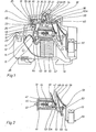
- Terminals 11 and 12 are located on the narrow sides of the base in a housing 10, which is of narrow construction and has a base-like shape.
- the terminal lug 13 associated with terminal 12 extends into the interior of housing 10 into an angle 14, on which a strand 15 is attached.
- the other end of the strand 15 is attached to a contact lever 16, which is designed as a double arm lever.
- a bend 16a is formed on the double-arm contact lever 16, in which an elongated hole 18 with its longitudinal extension is approximately transverse to the longitudinal extension of the contact lever 16, through which an axis 17 attached to two plates 19 extends and thus guides the contact lever 16.
- FIG. 1 only the rear board is partially visible and the front board is only visible to the left of a board holder (see below).
- the boards 19 are, as indicated by dashed lines in FIG. 1, L-shaped in the contour; the longer leg 20 of the board 19 carries, which is not shown, the axis 21 of a movable shift knob 22, whereas the short leg 23 carries the axis 17.
- the one lower board is bent in an L-shaped manner, with pin projections 24 being provided on the edge of the leg that projects perpendicular to the plane of the drawing, which engage in holes 25 of the other front board and are fixed there by means of deformations 26.
- the front board is fastened to the rear board, on which the pin projections 24 are formed. Both boards surround the entire switch lock like a fork, the structure of which is explained in more detail below.
- the contact lever 16 thus has a first arm 27 to which the movable contact piece 28 and the strand 15 are attached; On the other arm 29, an intermediate lever 31 is articulated via a hinge axis 30, the free end of which engages or guides a web 32 of a C-shaped wire bracket 33, which web 32 is additionally guided in an elongated hole 34 in a ratchet lever 35.
- the pawl lever 35 is rotatably supported at 36.
- the other web of the wire bracket 33 passes through a bore 22a in a formation 22b of the shift lever 22.
- a nose 37 is attached, which engages in a recess (not shown) on a release lever 38 and forms the latching point there with the latter.
- the trigger lever is also rotatably mounted on the axis 21.
- the movable contact lever 16 is arranged perpendicularly thereto, as is the trigger lever 37.
- a slide 39 runs approximately parallel to the elongated hole 34 and is guided in a groove 40 in the housing 10 so as to be displaceable in its longitudinal direction.
- thermal release 41 in the form of a thermal bimetal and a transmission lever 42, whose function is to be explained in more detail below, runs approximately perpendicular to the slide.
- a magnetic release 43 is arranged below the switching lock, the axis of the magnetic release 43 likewise running parallel to the front wall 10A and to the connecting line of the axes 30, 36, 32 and the elongated hole 34 and the slide 39.
- the known magnetic trigger has a movable magnet armature 43 and a magnetic core 45, the magnetic core 45 being penetrated by a plunger 46 which ends in a plunger head 47 which, when tightened in FIG Direction of arrow F strikes the arm of the contact lever 27 and the contact lever 27 opens.
- the magnet armature 44 continues in a pin 48 with a plate-like extension 49, which cooperates with one leg of the lever 42; this lever 42 is articulated at 50 on the yoke 51 of the magnetic release.
- the yoke 51 is U-shaped, with one leg of the yoke 51 running approximately parallel to the contact lever 16.
- an extension 53 is formed, which is again U-shaped, on the lower web 54 of which a tab 55 is angled, to which the thermal release 41 is attached.
- An adjusting screw 56 is arranged between the two legs of the U-shaped extension 53, the end of which is supported on the inner surface of the left leg, whereas the adjusting screw 56 is screwed into the other leg 57.
- Both legs 57, 57A are at a minimum distance when the adjusting screw 56 is unscrewed.
- the legs 57, 57A are pressed apart by the adjusting screw 56, and when the adjusting screw 56 is turned, the distance between the two legs 57 and 57A is expanded or reduced, so that the thermal release can be adjusted in this way.
- a strand 58 is attached, the other end of which is attached to a connecting tab 59.
- arc-quenching plate packet 60 which is delimited by a first arc-guiding rail 61 and a second arc-guiding rail 62.
- the arc guide rail 61 continues to the left in a U-shaped horn 63, the free leg of which carries the fixed contact piece 64.
- the arc guide rail 62 connects to the terminal lug 13. It is arcuate, which improves the arc running.
- the head 47 of the plunger 46 is moved in the direction of the arrow F via the magnet armature, as a result of which the movable contact lever 16 is moved into the open position.
- the slide 49 is moved to the right by means of the extension 49 of the magnet armature 44 and the transmission lever 50, as a result of which the release on the nose 37 is released and the contact lever is rotated clockwise under the pressure of the spring 65.
- the bracket 33 is moved to the right via the connecting lever 31, as a result of which the switching toggle 22 rotates counterclockwise into the switched-off position, and the movable contact lever 16 is held in the open position.
- the key switch has thus opened the contact points permanently.
- the thermal release 41 responds, for example in the event of an overcurrent, then it bends counterclockwise F in a clockwise direction around the fastening point 55, as a result of which the slide 39 is moved to the right and the latching point is released with the nose 37. This also opens the switch permanently.
- the switching lock is connected to the switching toggle 22 and the contact lever 16 and, via the strand 15, also to the left terminal 12 to form a unit which can be pre-assembled and inserted uniformly into the switch housing.
- Figure 2 shows that the arrangement of magnetic release, thermal release and terminal 11, also forms a unit that can be built into the housing of an electrical circuit breaker.
Landscapes
- Breakers (AREA)
- Arc-Extinguishing Devices That Are Switches (AREA)
- Emergency Protection Circuit Devices (AREA)
- Burglar Alarm Systems (AREA)
- Control Of Eletrric Generators (AREA)
- Glass Compositions (AREA)
- Saccharide Compounds (AREA)
- Switch Cases, Indication, And Locking (AREA)
Priority Applications (1)
| Application Number | Priority Date | Filing Date | Title |
|---|---|---|---|
| AT84113549T ATE27205T1 (de) | 1983-11-24 | 1984-11-09 | Leitungsschutzschalter. |
Applications Claiming Priority (2)
| Application Number | Priority Date | Filing Date | Title |
|---|---|---|---|
| DE3342469 | 1983-11-24 | ||
| DE19833342469 DE3342469A1 (de) | 1983-11-24 | 1983-11-24 | Elektrischer schalter |
Publications (3)
| Publication Number | Publication Date |
|---|---|
| EP0144799A2 true EP0144799A2 (fr) | 1985-06-19 |
| EP0144799A3 EP0144799A3 (en) | 1985-07-10 |
| EP0144799B1 EP0144799B1 (fr) | 1987-05-13 |
Family
ID=6215132
Family Applications (1)
| Application Number | Title | Priority Date | Filing Date |
|---|---|---|---|
| EP84113549A Expired EP0144799B1 (fr) | 1983-11-24 | 1984-11-09 | Disjoncteur |
Country Status (4)
| Country | Link |
|---|---|
| EP (1) | EP0144799B1 (fr) |
| JP (1) | JPS60131728A (fr) |
| AT (1) | ATE27205T1 (fr) |
| DE (2) | DE3342469A1 (fr) |
Cited By (9)
| Publication number | Priority date | Publication date | Assignee | Title |
|---|---|---|---|---|
| DE3733595A1 (de) * | 1987-10-05 | 1989-04-20 | Asea Brown Boveri | Elektrisches schaltgeraet |
| EP0352679A2 (fr) * | 1988-07-27 | 1990-01-31 | Asea Brown Boveri Aktiengesellschaft | Appareillage interrupteur électrique |
| EP0621619A1 (fr) * | 1993-04-22 | 1994-10-26 | Heinrich Kopp Ag | Disjoncteur de ligne |
| DE4406670A1 (de) * | 1994-03-01 | 1995-09-14 | Kopp Heinrich Ag | Leitungsschutzschalter |
| EP0880159A2 (fr) * | 1997-05-23 | 1998-11-25 | CMC Carl Maier + Cie AG | Interrupteur limiteur de courant |
| DE102004055564A1 (de) * | 2004-11-18 | 2006-06-01 | Abb Patent Gmbh | Elektrisches Installationsschaltgerät |
| EP1995754A1 (fr) | 2007-05-23 | 2008-11-26 | Abb Ag | Commutateur d'installation électrique |
| DE102008006863A1 (de) | 2007-05-23 | 2009-01-22 | Abb Ag | Elektrisches Installationsschaltgerät |
| CN111710570A (zh) * | 2020-07-22 | 2020-09-25 | 南京贝思特信息科技有限公司 | 一种断路器用自动隔断式隔弧罩 |
Families Citing this family (8)
| Publication number | Priority date | Publication date | Assignee | Title |
|---|---|---|---|---|
| DE3431663A1 (de) * | 1984-08-29 | 1986-03-13 | Brown, Boveri & Cie Ag, 6800 Mannheim | Kupplung fuer l-schutzschalterpole |
| DE3637275C1 (en) * | 1986-11-03 | 1988-05-05 | Flohr Peter | Overcurrent trip device for protection switching apparatuses |
| DE3915127C1 (fr) * | 1989-05-09 | 1990-09-06 | Flohr, Peter, Dipl.-Ing., 7790 Messkirch, De | |
| DE4040263A1 (de) * | 1990-12-17 | 1992-06-25 | Abb Patent Gmbh | Installationsgeraet |
| DE4040301A1 (de) * | 1990-12-17 | 1992-07-02 | Geyer Gmbh & Co Christian | Schaltmechanismus |
| DE19834474A1 (de) * | 1998-07-30 | 2000-02-10 | Siemens Ag | Einrichtung zum Kurzschlußschutz |
| DE19951249C2 (de) * | 1999-10-25 | 2001-11-08 | Abl Sursum Bayerische Elektroz | Schutzschalter mit RESET-Stellung |
| DE102005029059A1 (de) * | 2005-06-23 | 2006-12-28 | Abb Patent Gmbh | Schaltgerät, Leitungsschutzschalter und dergleichen |
Citations (7)
| Publication number | Priority date | Publication date | Assignee | Title |
|---|---|---|---|---|
| CH483114A (de) * | 1968-07-06 | 1969-12-15 | Stotz Kontakt Gmbh | Leitungsschutzschalter |
| FR2113887A1 (fr) * | 1970-11-12 | 1972-06-30 | Siemens Ag | |
| DE7500060U (de) * | 1975-01-03 | 1975-05-22 | Boshof R | Leitungsschutzschalter in Schmalbauweise und niedriger Bauart |
| FR2415360A1 (fr) * | 1978-01-24 | 1979-08-17 | Felten & Guilleaume Carlswerk | Montage de connexion, pour contacteur de protection de conducteurs dans un mode de construction plate |
| DE2943695A1 (de) * | 1979-10-30 | 1981-05-14 | Licentia Patent-Verwaltungs-Gmbh, 6000 Frankfurt | Schaltmechanismus fuer leitungsschutzschalter |
| EP0028958A1 (fr) * | 1979-10-26 | 1981-05-20 | Legrand | Disjoncteur, son mécanisme de déclenchement |
| DE3226820A1 (de) * | 1981-08-13 | 1983-07-14 | Kombinat Veb Keramische Werke Hermsdorf, Ddr 6530 Hermsdorf | Leitungsschutzschalter in schmalbauweise |
Family Cites Families (4)
| Publication number | Priority date | Publication date | Assignee | Title |
|---|---|---|---|---|
| CH508293A (de) * | 1969-11-15 | 1971-05-31 | Bbc Brown Boveri & Cie | Schalttafelgerüst |
| DE2336222A1 (de) * | 1973-07-17 | 1975-01-30 | Baco Const Elect | Schaltmechanismus fuer selbstschalter |
| DE7327872U (de) * | 1973-07-30 | 1973-11-15 | Baco Constructions Electriques Anc Baumgarten | Leitungsschutzschalter |
| DE2616825C3 (de) * | 1976-04-15 | 1981-07-02 | Brown, Boveri & Cie Ag, 6800 Mannheim | Leitungsschutzschalter |
-
1983
- 1983-11-24 DE DE19833342469 patent/DE3342469A1/de not_active Withdrawn
-
1984
- 1984-11-09 DE DE8484113549T patent/DE3463708D1/de not_active Expired
- 1984-11-09 AT AT84113549T patent/ATE27205T1/de not_active IP Right Cessation
- 1984-11-09 EP EP84113549A patent/EP0144799B1/fr not_active Expired
- 1984-11-22 JP JP59246376A patent/JPS60131728A/ja active Pending
Patent Citations (7)
| Publication number | Priority date | Publication date | Assignee | Title |
|---|---|---|---|---|
| CH483114A (de) * | 1968-07-06 | 1969-12-15 | Stotz Kontakt Gmbh | Leitungsschutzschalter |
| FR2113887A1 (fr) * | 1970-11-12 | 1972-06-30 | Siemens Ag | |
| DE7500060U (de) * | 1975-01-03 | 1975-05-22 | Boshof R | Leitungsschutzschalter in Schmalbauweise und niedriger Bauart |
| FR2415360A1 (fr) * | 1978-01-24 | 1979-08-17 | Felten & Guilleaume Carlswerk | Montage de connexion, pour contacteur de protection de conducteurs dans un mode de construction plate |
| EP0028958A1 (fr) * | 1979-10-26 | 1981-05-20 | Legrand | Disjoncteur, son mécanisme de déclenchement |
| DE2943695A1 (de) * | 1979-10-30 | 1981-05-14 | Licentia Patent-Verwaltungs-Gmbh, 6000 Frankfurt | Schaltmechanismus fuer leitungsschutzschalter |
| DE3226820A1 (de) * | 1981-08-13 | 1983-07-14 | Kombinat Veb Keramische Werke Hermsdorf, Ddr 6530 Hermsdorf | Leitungsschutzschalter in schmalbauweise |
Cited By (14)
| Publication number | Priority date | Publication date | Assignee | Title |
|---|---|---|---|---|
| DE3733595A1 (de) * | 1987-10-05 | 1989-04-20 | Asea Brown Boveri | Elektrisches schaltgeraet |
| EP0352679A2 (fr) * | 1988-07-27 | 1990-01-31 | Asea Brown Boveri Aktiengesellschaft | Appareillage interrupteur électrique |
| EP0352679A3 (en) * | 1988-07-27 | 1990-08-22 | Asea Brown Boveri Aktiengesellschaft | Electrical switchgear |
| EP0621619A1 (fr) * | 1993-04-22 | 1994-10-26 | Heinrich Kopp Ag | Disjoncteur de ligne |
| DE4406670A1 (de) * | 1994-03-01 | 1995-09-14 | Kopp Heinrich Ag | Leitungsschutzschalter |
| DE4406670C3 (de) * | 1994-03-01 | 1999-09-09 | Kopp Heinrich Ag | Leitungsschutzschalter |
| EP0880159A3 (fr) * | 1997-05-23 | 1999-05-12 | CMC Carl Maier + Cie AG | Interrupteur limiteur de courant |
| EP0880159A2 (fr) * | 1997-05-23 | 1998-11-25 | CMC Carl Maier + Cie AG | Interrupteur limiteur de courant |
| DE102004055564A1 (de) * | 2004-11-18 | 2006-06-01 | Abb Patent Gmbh | Elektrisches Installationsschaltgerät |
| US7579933B2 (en) | 2004-11-18 | 2009-08-25 | Abb Patent Gmbh | Electrical installation switching device |
| DE102004055564B4 (de) | 2004-11-18 | 2022-05-05 | Abb Ag | Elektrisches Installationsschaltgerät |
| EP1995754A1 (fr) | 2007-05-23 | 2008-11-26 | Abb Ag | Commutateur d'installation électrique |
| DE102008006863A1 (de) | 2007-05-23 | 2009-01-22 | Abb Ag | Elektrisches Installationsschaltgerät |
| CN111710570A (zh) * | 2020-07-22 | 2020-09-25 | 南京贝思特信息科技有限公司 | 一种断路器用自动隔断式隔弧罩 |
Also Published As
| Publication number | Publication date |
|---|---|
| EP0144799B1 (fr) | 1987-05-13 |
| DE3463708D1 (en) | 1987-06-19 |
| DE3342469A1 (de) | 1985-06-05 |
| ATE27205T1 (de) | 1987-05-15 |
| JPS60131728A (ja) | 1985-07-13 |
| EP0144799A3 (en) | 1985-07-10 |
Similar Documents
| Publication | Publication Date | Title |
|---|---|---|
| EP0144799B1 (fr) | Disjoncteur | |
| DE10222667A1 (de) | Schaltgerät | |
| DE3242062C2 (fr) | ||
| EP0090176A2 (fr) | Disjoncteur de surintensité | |
| DE3037355C2 (de) | Schutzschalter kompakter Bauart mit einem Auslösestift | |
| EP1884976B1 (fr) | Dispositif de commutation doté d'un élément d'actionnement | |
| EP1284494B1 (fr) | Mécanisme de verrouillage pour un disjoncteur, en particulier pour disjoncteur pour moteur | |
| EP0243648B1 (fr) | Disjoncteur électrique | |
| DD221878A1 (de) | Mehrpoliger leitungsschutzschalter | |
| DE3734396A1 (de) | Elektrisches schaltgeraet | |
| DE3106004A1 (de) | Leistungsschalter | |
| EP0158241B1 (fr) | Interrupteur électrique | |
| EP0851449B1 (fr) | Appareil de commutation pour une installation électrique | |
| EP0849748A2 (fr) | Interrupteur électrique d'installation | |
| AT404647B (de) | Elektrischer schutzschalter | |
| DE3423541C2 (fr) | ||
| DE1292728B (de) | Druckknopfbetaetigter UEberstromschalter | |
| DE102006036194A1 (de) | Schaltvorrichtung mit Schaltstellenpaar | |
| DE953633C (de) | Elektrischer Schalter, insbesondere Installations-Selbstschalter mit geradlinig bewegtem Kontaktbrueckentraeger | |
| DE3347097A1 (de) | Schutzschalter | |
| DE3425996C2 (fr) | ||
| EP1037237A2 (fr) | Dispositif pour la fixation d' un déclencheur magnétique dans un disjoncteur à courant de défaut | |
| DE2047521A1 (de) | Installationsselbstschalter mit Verteileranordnung | |
| WO2003079389A1 (fr) | Disjoncteur avec interruption bipolaire | |
| EP1473751A1 (fr) | Déclencheur électromagnétique |
Legal Events
| Date | Code | Title | Description |
|---|---|---|---|
| PUAI | Public reference made under article 153(3) epc to a published international application that has entered the european phase |
Free format text: ORIGINAL CODE: 0009012 |
|
| PUAL | Search report despatched |
Free format text: ORIGINAL CODE: 0009013 |
|
| AK | Designated contracting states |
Designated state(s): AT BE CH DE FR GB IT LI NL SE |
|
| AK | Designated contracting states |
Designated state(s): AT BE CH DE FR GB IT LI NL SE |
|
| 17P | Request for examination filed |
Effective date: 19850716 |
|
| 17Q | First examination report despatched |
Effective date: 19860303 |
|
| GRAA | (expected) grant |
Free format text: ORIGINAL CODE: 0009210 |
|
| AK | Designated contracting states |
Kind code of ref document: B1 Designated state(s): AT BE CH DE FR GB IT LI NL SE |
|
| REF | Corresponds to: |
Ref document number: 27205 Country of ref document: AT Date of ref document: 19870515 Kind code of ref document: T |
|
| ITF | It: translation for a ep patent filed | ||
| ET | Fr: translation filed | ||
| REF | Corresponds to: |
Ref document number: 3463708 Country of ref document: DE Date of ref document: 19870619 |
|
| PLBE | No opposition filed within time limit |
Free format text: ORIGINAL CODE: 0009261 |
|
| STAA | Information on the status of an ep patent application or granted ep patent |
Free format text: STATUS: NO OPPOSITION FILED WITHIN TIME LIMIT |
|
| 26N | No opposition filed | ||
| PGFP | Annual fee paid to national office [announced via postgrant information from national office to epo] |
Ref country code: SE Payment date: 19891110 Year of fee payment: 6 |
|
| PG25 | Lapsed in a contracting state [announced via postgrant information from national office to epo] |
Ref country code: SE Effective date: 19901110 |
|
| ITTA | It: last paid annual fee | ||
| EUG | Se: european patent has lapsed |
Ref document number: 84113549.4 Effective date: 19910705 |
|
| PGFP | Annual fee paid to national office [announced via postgrant information from national office to epo] |
Ref country code: NL Payment date: 20001106 Year of fee payment: 17 |
|
| PGFP | Annual fee paid to national office [announced via postgrant information from national office to epo] |
Ref country code: BE Payment date: 20001121 Year of fee payment: 17 |
|
| PGFP | Annual fee paid to national office [announced via postgrant information from national office to epo] |
Ref country code: CH Payment date: 20011026 Year of fee payment: 18 |
|
| PGFP | Annual fee paid to national office [announced via postgrant information from national office to epo] |
Ref country code: AT Payment date: 20011029 Year of fee payment: 18 |
|
| PG25 | Lapsed in a contracting state [announced via postgrant information from national office to epo] |
Ref country code: BE Free format text: LAPSE BECAUSE OF NON-PAYMENT OF DUE FEES Effective date: 20011130 |
|
| REG | Reference to a national code |
Ref country code: GB Ref legal event code: IF02 |
|
| BERE | Be: lapsed |
Owner name: BROWN BOVERI & CIE A.G. Effective date: 20011130 |
|
| PG25 | Lapsed in a contracting state [announced via postgrant information from national office to epo] |
Ref country code: NL Free format text: LAPSE BECAUSE OF NON-PAYMENT OF DUE FEES Effective date: 20020601 |
|
| NLV4 | Nl: lapsed or anulled due to non-payment of the annual fee |
Effective date: 20020601 |
|
| PG25 | Lapsed in a contracting state [announced via postgrant information from national office to epo] |
Ref country code: AT Free format text: LAPSE BECAUSE OF NON-PAYMENT OF DUE FEES Effective date: 20021109 |
|
| PG25 | Lapsed in a contracting state [announced via postgrant information from national office to epo] |
Ref country code: LI Free format text: LAPSE BECAUSE OF NON-PAYMENT OF DUE FEES Effective date: 20021130 Ref country code: CH Free format text: LAPSE BECAUSE OF NON-PAYMENT OF DUE FEES Effective date: 20021130 |
|
| REG | Reference to a national code |
Ref country code: CH Ref legal event code: PL |
|
| PGFP | Annual fee paid to national office [announced via postgrant information from national office to epo] |
Ref country code: DE Payment date: 20030929 Year of fee payment: 20 |
|
| PGFP | Annual fee paid to national office [announced via postgrant information from national office to epo] |
Ref country code: FR Payment date: 20031001 Year of fee payment: 20 |
|
| PGFP | Annual fee paid to national office [announced via postgrant information from national office to epo] |
Ref country code: GB Payment date: 20031106 Year of fee payment: 20 |
|
| PG25 | Lapsed in a contracting state [announced via postgrant information from national office to epo] |
Ref country code: GB Free format text: LAPSE BECAUSE OF EXPIRATION OF PROTECTION Effective date: 20041108 |
|
| REG | Reference to a national code |
Ref country code: GB Ref legal event code: PE20 |