EP0851449B1 - Appareil de commutation pour une installation électrique - Google Patents
Appareil de commutation pour une installation électrique Download PDFInfo
- Publication number
- EP0851449B1 EP0851449B1 EP97121578A EP97121578A EP0851449B1 EP 0851449 B1 EP0851449 B1 EP 0851449B1 EP 97121578 A EP97121578 A EP 97121578A EP 97121578 A EP97121578 A EP 97121578A EP 0851449 B1 EP0851449 B1 EP 0851449B1
- Authority
- EP
- European Patent Office
- Prior art keywords
- lever
- push button
- switching device
- service switching
- sliding surface
- Prior art date
- Legal status (The legal status is an assumption and is not a legal conclusion. Google has not performed a legal analysis and makes no representation as to the accuracy of the status listed.)
- Expired - Lifetime
Links
Images


Classifications
-
- H—ELECTRICITY
- H01—ELECTRIC ELEMENTS
- H01H—ELECTRIC SWITCHES; RELAYS; SELECTORS; EMERGENCY PROTECTIVE DEVICES
- H01H71/00—Details of the protective switches or relays covered by groups H01H73/00 - H01H83/00
- H01H71/10—Operating or release mechanisms
- H01H71/50—Manual reset mechanisms which may be also used for manual release
- H01H71/58—Manual reset mechanisms which may be also used for manual release actuated by push-button, pull-knob, or slide
-
- H—ELECTRICITY
- H01—ELECTRIC ELEMENTS
- H01H—ELECTRIC SWITCHES; RELAYS; SELECTORS; EMERGENCY PROTECTIVE DEVICES
- H01H13/00—Switches having rectilinearly-movable operating part or parts adapted for pushing or pulling in one direction only, e.g. push-button switch
- H01H13/50—Switches having rectilinearly-movable operating part or parts adapted for pushing or pulling in one direction only, e.g. push-button switch having a single operating member
- H01H13/56—Switches having rectilinearly-movable operating part or parts adapted for pushing or pulling in one direction only, e.g. push-button switch having a single operating member the contact returning to its original state upon the next application of operating force
- H01H13/562—Switches having rectilinearly-movable operating part or parts adapted for pushing or pulling in one direction only, e.g. push-button switch having a single operating member the contact returning to its original state upon the next application of operating force making use of a heart shaped cam
Definitions
- the invention relates to an installation switching device, in particular a single-pole circuit breaker according to the preamble of claim 1.
- Single-pole circuit breakers are generally designed so that the pole, the is a complete single-pole circuit breaker, each with a tripping unit electromagnetic and a thermal release, a key switch with a latching point and with an actuator coupled to it and a contact apparatus, has an arcing chamber and terminals.
- a push button switch of the type mentioned is known from DE 1051948 B. become.
- this push button switch is designed so that the key switch is relatively complicated and that another push button is provided with which the switch can be turned off.
- the object of the invention is an installation switching device of the type mentioned, in particular to create a single-pole circuit breaker, which simplifies the structure is trained.
- the push button there is a running in the push button in the direction of movement of the push button Elongated hole arranged in which one end of the coupling element is guided; at the Klinkhebel a nose is provided, the latching point with the coupling element forms; the coupling element is a U-shaped bracket, one leg in the Elongated hole and the other leg is coupled to the contact lever; the Jack lever works with one of the electromagnetic and thermal Trigger actuated transmission member designed as a striker together.
- the pawl lever is an L-shaped pawl, one Has leg that runs approximately parallel to the direction of movement of the push button and their perpendicular to the leg in connection with the hammer stands.
- the latch lever is constantly under the pressure of a spring this applied towards the impact lever.
- the special embodiment of the push button goes from claims 10 and 11 out; a latching lever cooperates with the sliding surfaces, which holds the push button in the depressed position and from the movable Contact lever can be pushed off the sliding surfaces.
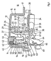
- circuit breaker according to FIG. 1, which has the reference number 10 in its entirety is only with respect to the components switch lock, actuating element, thermal and magnetic release and contact point shown. terminals and the extinguishing chamber are not shown for the sake of simplicity.
- the circuit breaker has a housing 11 in which a contact point (see below) is used.
- the housing 11 has the line protection circuit Usual outer contour with a front side 12, from which a formed as a push button 13 Actuator protrudes; the front wall 12 is parallel to the floor surface aligned, which in a known but not shown here a Has recess for snapping onto a top-hat rail.
- Perpendicular to the Front wall 12 run two side wall sections 14 and 15, which are parallel to the bottom wall or pass over to the front wall sections 16 and 17 which Have openings, not shown, through which the clamping screws of terminals are accessible.
- an electromagnetic trigger 18 is used, the The central axis of the coil 19 of the trigger 18 runs approximately parallel to the front wall 12.
- the Electromagnetic trigger 18 has a striking armature 20 that emerges from the web 21 of a U-shaped yoke 22 which projects a first leg 23 and one has second leg 24, which also run parallel to the front wall 12.
- the Leg 23 has tabs 25 bent towards the front wall, in which the Axis of rotation 26 of an L-shaped striking lever 27 is mounted.
- the longer web 28 of the Impact lever runs parallel to the web 21 and overlaps or projects over it, whereas the short web 29, which projects in the same direction from the longer web 28 as the leg 23, the axis of rotation 26 carries.
- the impact anchor 20 is designed in this way or arranged so that it against the longer leg 28 of the striking lever 27th comes to rest and when triggered or responding about its axis 26 swiveled clockwise.
- Extensions 30 are formed on the leg 24 and extend in the longitudinal direction of the coil 19 run and protrude beyond it.
- a thermal release 34 is on the extension 30 attached in the form of a thermal bimetal.
- At 31 is an adjustment device for the Thermal bimetal 34 referred to, which is not described here.
- the bimetallic strip 34 runs parallel to the longitudinal axis of the coil 19 and projects above it Bridge 21.
- a release lever 36 can be rotated via an axis of rotation 37 stored, which rests with a nose 38 against the bimetal 34 on the side, in which deflects the bimetal 34.
- a projection 39 is connected to the axis 37, such that when the lever 36 rotates counterclockwise is that the bimetal 34 presses against the nose 38, the projection 39th strikes against a projection 40 which is integrally formed on the leg 28, so that at Rotate the release lever 36 clockwise over the projection 39 of the striking lever 27 is rotated about the axis 26.
- the movement of the push button 13 is perpendicular to the front wall 12.
- the push button has a cylindrical portion 42 in which a blind hole 43 of the side opposite the pressing surface 44 is introduced; in this A blind spring 43 has a compression spring 45.
- An elongated hole 95 is made in the push button 13, which is perpendicular to the front wall 12 and runs in the direction of movement of the push button 13.
- the key switch comprises a transmission bracket 60 which with a leg 59 in the slot 95 engages and that with the other leg 61 with the lever arm 62 a contact carrier 63 designed here as a contact shaft is connected, in which a Contact lever 64 is rotatably mounted with the movable contact piece 65.
- the contact lever 64 also has one on the opposite side of the contact point Actuating arm 66 which, as shown below, is triggered when triggered the pin 67 of a locking arm 68 strikes, so that the locking arm 68 in the drawing Fig. 1 can be moved to the left.
- the movable contact piece 65 acts with one Fixed contact piece 69 together.
- the pawl lever 90 is L-shaped and has a first leg 91 which is parallel to the Direction of movement of the push button 13 extends. He also has a web 92, the is aligned parallel to the front wall 12 and furthermore an extension 93 which complements the latch lever 90 to a U-shape, with the open side of the U-shape to Front wall 12 is executed.
- the extension 93 acts with the leg 28 of the striking lever 27 together.
- a nose 94 is formed, and the latch lever 90 is pressed to the right by means of the spring 45; the nose 94 serves as a stop for the leg 59 of the bracket 60, the arm 62 of the contact carrier at the other end 63 is articulated.
- the thermal bimetal 34 bends counterclockwise due to an overcurrent and pivots the arm 36 and over the projection 39, the striking lever 27 pivoted clockwise about the axis 26, whereby the pawl lever 90th is pivoted counterclockwise; the switch is released, the bracket 60 is released and moves upward in the slot or slot 95, whereby the contact carrier 63 can go into the switched-off position with the contact lever 64.
- the push button 13 is drawn again in FIG. 3 with its cylindrical section 42, the surface lying at the top in the drawing (at 44) being the pressing surface which is not visible.
- a first projection 114 and a second projection 115 adjoin the opposite circular surface 113 of the cylindrical section 42; the second projection 115 has an approximately rectangular shape and carries a sliding surface arrangement 116 on one of the broad sides.
- the sliding surface arrangement 116 has a first sliding surface 117 running approximately parallel to the direction of movement of the push button 13 and a second sliding surface 118 running parallel to it, in its region on the pressure surface side are connected to one another via a connection point 119 and also via a connection point 120 on the back surface side.
- both sliding surfaces 117 and 118 are at different distances: the first sliding surface rises slightly from the connection point 120 to one in the area of the connection point 119 located saddle surface 121, which drops to the actual connection point 119 via a step 122. Via a further step 123, the connecting point 119 drops to the second sliding surface 118, which rises up to the connecting point 120 in relation to this reference plane, so that a third step 124 is provided at the connecting point 120 between the second sliding surface 118 and the first sliding surface 117. over which the second sliding surface 118 drops to the first sliding surface 117.
- connection point 119 Between the sliding surfaces 118 and 117 there is a dividing wall 125, which is provided with a latching bag 126 on the connection point 119, that is to say the connection point 119 close to the pressing surface. If a nose 135 resiliently transverse to the sliding surfaces 117 and 118 (see below) slides along the sliding surfaces 117 and 118, then it first slides in the direction of the arrow P 1 (relative movement) on the sliding surface 117 upwards to the saddle surface 121 and slips from there the step 122 on the connection point 119 and in the rest bag 126, whereby the push button 13 is held in the pressed-in position.
- the connection point 119 of the two sliding surfaces 117 and 118 is closed at the top, i.e.
- step 127 running perpendicular to it, which extends at an angle of 45 ° to the direction of movement of the push button and merges into step 122, the step 127 or boundary wall 127 runs parallel to the V surface 128 of the rest bag 126 adjacent to the sliding surface 118. If the push button 13 is pushed in further, the locking lug moves in the direction of the arrow P 2 and is deflected via the step 127 and the further step 123 towards the second sliding surface 118 and then slides on the second sliding surface when the push button slides up again 118 to the second connection point 120 and snaps back onto the first slideway 117 via the step 124.
- the latching nose is therefore guided on the one hand by the partition 125, the step 127 and a boundary wall 129 running parallel to the partition 125, between which the second sliding surface 118 runs.
- the boundary wall 129 has in the area of the connection point 120 an arc 130 inclined towards the sliding surface 117.
- the locking lug is guided between the boundary wall 129 with the arch 130 and the partition wall 125 on the sliding surface 118.
- the locking element thus makes a movement perpendicular to the reference plane and also a rotation about an axis of rotation that is perpendicular runs to the reference plane.
- a spring arrangement is provided, which continues is described in more detail below.
- the reference plane for the slideway 116 runs parallel to the central axis of the cylindrical region 42 of the push button and parallel to Elongated hole 95, the direction of breakthrough of the elongated hole 114 also parallel runs to the reference surface for the slideway 116.
- the push button 13 continuously upwards suppressed.
- the push-in movement is the movement in the direction of arrow E and the push-out movement is the movement in the direction of arrow A. Movement E is manual and the movement A due to the compression spring in the bore 133.
- Between a space 115a is provided for the two projections 114 and 115, in which the pawl lever 90 is received.
- the gap 115a begins certain extent into the bore 43 into it, so that part of the ratchet lever 90 also extends into the cylindrical part 42 of the push button 13.
- To recognize is a transverse bore in the extension 115 which the axis 46 for the pawl lever 90th receives.
- This locking element 134 has one Nose 135, which runs approximately parallel to the direction of movement of the push button 13 Arm 68 is formed, which is connected to the transverse bolt 67 is; the pin 67 is displaceable in its axial direction, so that the Arm 68 is slidable; in addition, the bolt 67 is also rotatable about its Longitudinal axis, so that the arm 68 is pivotable about the pin axis 67.
- a spring 67a is provided, which is designed as a helical spring and against it Pushing force of the bolts 67 with the locking arm 68, from the actuating arm 66 of the contact lever 64 driven when switching off, is displaceable so that the nose 135 is lifted off the sliding arrangement 116.
- the spring 67a is with her, the Locking arm 68 remote end mounted stationary. So z. B. with a free trip (see also below) the nose 135 raised above the partition 125 are so that they slide from the sliding surface 117 on the sliding surface 118 and against the boundary wall 129 can come to rest.
- the spring 67a is with her end near the latch arm with a bend 67b in a receiving hole 68a in the latch arm 68 inserted so that it also serves as a torsion spring for the bolt 67 and the locking arm 68 serves, with which the bolt 67 is acted on so that the nose 135 always counter clockwise on the slide assembly or slideway 116 around the partition 125 runs around when the push button 13 is actuated.
- the axis of rotation 138 Contact shaft 63 is rotatably mounted with the contact lever 64, which is the movable Contact piece 65 and on the opposite side has a stop 66 which bears against the end face of the bolt 67.
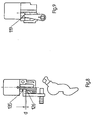
- FIG. 4 and 5 show the arrangements in the off position, that is when Push button 13 completely protrudes from the switching device.
- the detent 135 is located itself at the connection point 120.
- the movable contact piece 65 is in its Off position.
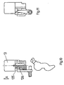
- push button 13 is pressed in the direction of arrow E, whereby via the bracket 60 (Fig. 1), the contact shaft 63 and the movable contact lever 64 comes into contact with a fixed contact piece 69.
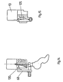
- the Locking element 135 is still on the sliding surface 117 at a certain distance to the connection point 119. If the push button 13 is pushed in further, then the locking lug 135 is in the area of the connection point 119 in the locking sack 126 snap; can be seen in Fig.
- the locking element is also moved via the movable contact lever 64 whose actuating arm 66 out of the sliding surface 117 against the pressure of the spring 67a pushed out and by the torque of the spring 67a over the partition 125th pressed against the boundary wall 129, causing the push button to lock 13 in the on position and a latching of the switch prevented and is avoided.
Landscapes
- Breakers (AREA)
- Input Circuits Of Receivers And Coupling Of Receivers And Audio Equipment (AREA)
- Circuits Of Receivers In General (AREA)
- Exchange Systems With Centralized Control (AREA)
- Push-Button Switches (AREA)
Claims (14)
- Appareil de commutation pour installations, en particulier disjoncteur de protection de ligne, avec un pôle avec un déclencheur magnétique (18) et un déclencheur thermique (34) associés, avec un système de contacts (65, 69), avec une chambre de soufflage d'arc et avec des bornes de connexion, dans lequel il est prévu comme élément d'actionnement un bouton-poussoir (13) sur lequel est monté un levier à cliquet (90) actionnable par les déclencheurs thermique (34) et électro-magnétique (18), qui, avec un élément de couplage (60) lié à un levier de contact (64), forme un point d'encliquetage sur le bouton-poussoir, de telle sorte que lors du déclenchement, le levier de contact (64) pivote dans le sens de la coupure, caractérisé en ce qu'un trou oblong (95) qui s'étend dans la direction de déplacement du bouton-poussoir (13) est aménagé dans le bouton-poussoir (13), en ce qu'une extrémité de l'élément de couplage (60) est guidée dans le trou oblong (95), en ce qu'il est prévu sur le levier à cliquet (90) une dent (94) qui, avec l'élément de couplage (60), forme le point d'encliquetage, en ce que l'élément de couplage (60) est un étrier en forme de U, dont une branche (59) est guidée dans le trou oblong (95) et dont l'autre branche (61) est couplée au levier de contact (64), en ce que le levier à cliquet (90) coopère avec un organe de transmission (27) conformé en levier battant actionné par les déclencheurs électro-magnétique et thermique (18, 34).
- Appareil de commutation pour installations selon la revendication 1, caractérisé en ce que le levier de contact (64) est monté dans un arbre de contact (63) rotatif, stationnaire, et traverse celui-ci transversalement et en ce que l'étrier (60) en forme de U est couplé à l'arbre de contact (63).
- Appareil de commutation pour installations selon une des revendications 1 ou 2, caractérisé en ce que le levier à cliquet (90) monté pivotant sur le bouton poussoir (13) a une forme de L, dont une aile (91) est sensiblement parallèle à la direction de déplacement du bouton-poussoir (13) et l'autre aile (92), perpendiculaire à la première, est reliée au levier battant (27).
- Appareil de commutation pour installations selon la revendication 3, caractérisé en ce que l'autre aile (92) présente un prolongement (93) sensiblement perpendiculaire qui définit avec la première aile (91) une forme de U et en ce que le prolongement est en appui sur le levier battant.
- Appareil de commutation pour installations selon la revendication 4, caractérisé en ce que le prolongement forme un angle obtus avec l'autre aile.
- Appareil de commutation pour installations selon une des revendications précédentes, caractérisé en ce que le levier à cliquet (90) est soumis de manière permanente à la pression d'un ressort (45) qui s'exerce en direction du levier battant (27).
- Appareil de commutation pour installations selon la revendication 6, caractérisé en ce que le ressort (45) est logé à l'intérieur du bouton-poussoir (13).
- Appareil de commutation pour installations selon la revendication 7, caractérisé en ce que le ressort est logé dans un trou borgne aménagé dans la partie cylindrique du bouton-poussoir.
- Appareil de commutation pour installations selon une des revendications précédentes, caractérisé en ce que le levier battant (27) couvre l'armature mobile (20) du système d'électro-aimant et peut être actionné par le déclencheur thermique par l'intermédiaire chaque fois d'un élément de transmission.
- Appareil de commutation pour installations selon une des revendications précédentes, caractérisé en ce que l'élément d'encliquetage (134) glisse en étant appliqué élastiquement sur un agencement de surfaces de glissement (117, 118) sur le bouton-poussoir (13), en ce que l'agencement de surfaces de glissement (117, 118) comprend deux surfaces (117, 118) sensiblement parallèles qui s'étendent dans la direction de coulissement et forment une piste de glissement fermée, entre lesquelles est prévue une cloison de séparation (125), l'élément d'encliquetage (134) glissant sur la première surface de glissement (117) lorsqu'on enfonce le bouton-poussoir (13) et sur la seconde surface de glissement (118) lors du mouvement de sortie du bouton-poussoir (13), et en ce qu'il est prévu dans la cloison de séparation (125), sur le trajet de glissement, au niveau du point de rencontre (119) des surfaces de glissement (117, 118) voisin de la surface de pression, un cran d'encliquetage (126), dans lequel l'élément d'encliquetage (134) s'enclenche lorsqu'on enfonce le bouton-poussoir (13) et qui retient celui-ci dans la seconde position enfoncée stable.
- Appareil de commutation pour installations selon la revendication 10, caractérisé en ce que les surfaces de glissement (117, 118) présentent des distances différentes par rapport à une surface de référence, un troisième gradin (124) d'une surface de glissement à l'autre (117, 118) étant prévu au niveau du point de rencontre (120) entre les surfaces de glissement éloigné de la surface de pression, lequel gradin empêche que l'élément d'encliquetage (134) arrive sur la deuxième surface de glissement lorsqu'on presse le bouton-poussoir (13).
- Appareil de commutation pour installations selon une des revendications précédentes, caractérisé en ce que l'élément d'encliquetage (134) comporte un levier de maintien (bras 136) pourvu d'une dent (135) perpendiculaire, qui pivote autour d'un axe perpendiculaire aux plans des surfaces de glissement et peut être déplacé sur le même axe par la pièce de contact mobile (65), à l'encontre de la force d'un ressort et ainsi être décollé des surfaces de glissement (117, 118).
- Appareil de commutation pour installations selon la revendication 12, caractérisé en ce que le levier de maintien (68) est monté sur un axe (67) tournant, sur la face frontale duquel appuie le levier de contact (64) portant la pièce de contact mobile (65).
- Appareil de commutation pour installations selon la revendication 12 ou 13, caractérisé en ce que le levier de maintien (68) est sollicité élastiquement en rotation autour de l'axe (67), de telle sorte que la dent soit repoussée de la première surface de glissement (117) dans le cran d'encliquetage (126), puis de nouveau sur la deuxième surface de glissement (118).
Applications Claiming Priority (2)
| Application Number | Priority Date | Filing Date | Title |
|---|---|---|---|
| DE19653265A DE19653265A1 (de) | 1996-12-20 | 1996-12-20 | Installationsschaltgerät |
| DE19653265 | 1996-12-20 |
Publications (2)
| Publication Number | Publication Date |
|---|---|
| EP0851449A1 EP0851449A1 (fr) | 1998-07-01 |
| EP0851449B1 true EP0851449B1 (fr) | 2002-10-23 |
Family
ID=7815511
Family Applications (1)
| Application Number | Title | Priority Date | Filing Date |
|---|---|---|---|
| EP97121578A Expired - Lifetime EP0851449B1 (fr) | 1996-12-20 | 1997-12-08 | Appareil de commutation pour une installation électrique |
Country Status (3)
| Country | Link |
|---|---|
| EP (1) | EP0851449B1 (fr) |
| AT (1) | ATE226757T1 (fr) |
| DE (2) | DE19653265A1 (fr) |
Families Citing this family (1)
| Publication number | Priority date | Publication date | Assignee | Title |
|---|---|---|---|---|
| CN108461357A (zh) * | 2018-03-21 | 2018-08-28 | 上海良信电器股份有限公司 | 一种断路器操作装置的分合闸指示装置 |
Family Cites Families (9)
| Publication number | Priority date | Publication date | Assignee | Title |
|---|---|---|---|---|
| DD15750A (fr) * | ||||
| FR963947A (fr) * | 1947-09-16 | 1950-07-26 | ||
| DE1051948B (de) * | 1957-01-19 | 1959-03-05 | Elektroinstallation Annaberg V | Schaltmechanismus fuer elektrische Kleinselbstschalter |
| US3142737A (en) * | 1960-09-09 | 1964-07-28 | Wood Electric Corp | Heat responsive wire circuit breaker |
| CH409091A (de) * | 1964-06-01 | 1966-03-15 | Weber Ag Fab Elektro | Selbstschalter |
| DE1513323C3 (de) * | 1965-10-15 | 1974-01-31 | Ellenberger & Poensgen Gmbh, 8503 Altdorf | Druckknopfbetätigter thermischer Überstromschalter |
| DE2417330A1 (de) * | 1974-04-09 | 1975-11-06 | Mecanismos Aux Ind | Umschalter |
| FR2703822B1 (fr) * | 1993-04-07 | 2002-01-25 | Merlin Gerin | Disjoncteur multipolaire à assemblage modulaire . |
| DE69501321T2 (de) * | 1995-06-06 | 1998-04-16 | Signal Lux Spa | Sicherheitsschalter, insbesondere für elektrische Haushaltsgeräte |
-
1996
- 1996-12-20 DE DE19653265A patent/DE19653265A1/de not_active Withdrawn
-
1997
- 1997-12-08 AT AT97121578T patent/ATE226757T1/de not_active IP Right Cessation
- 1997-12-08 EP EP97121578A patent/EP0851449B1/fr not_active Expired - Lifetime
- 1997-12-08 DE DE59708556T patent/DE59708556D1/de not_active Expired - Lifetime
Also Published As
| Publication number | Publication date |
|---|---|
| ATE226757T1 (de) | 2002-11-15 |
| DE19653265A1 (de) | 1998-06-25 |
| EP0851449A1 (fr) | 1998-07-01 |
| DE59708556D1 (de) | 2002-11-28 |
Similar Documents
| Publication | Publication Date | Title |
|---|---|---|
| EP0543208B1 (fr) | Disjoncteur de protection avec bascule | |
| EP1760747B1 (fr) | Disjoncteur électrique | |
| EP1760748B1 (fr) | Appareil de commutation électrique | |
| EP0111662B1 (fr) | Interrupteur électrique | |
| WO2003007322A1 (fr) | Appareil de connexion a verrouillage de connexion | |
| EP1728260B1 (fr) | Mecanisme de commutation pour appareil de distribution d'installation electrique | |
| EP0303965A2 (fr) | Appareil de commutation électrique | |
| EP1884976B1 (fr) | Dispositif de commutation doté d'un élément d'actionnement | |
| EP0391086A1 (fr) | Dispositeur de protection à courant excessif commandé par un bouton-poussoir | |
| DE10216439A1 (de) | Hilfsschalter | |
| DE2616554C2 (de) | Elektrischer Installationsschalter, insbesondere Leitungsschutzschalter mit Fehlerstromschutzeinrichtung | |
| EP0851449B1 (fr) | Appareil de commutation pour une installation électrique | |
| EP0849759B1 (fr) | Appareil de coupure pour une installation électrique | |
| DE3119165A1 (de) | Selbstschalter als baueinheit aus einem leitungsschutzschalter sowie hilfs- und signalschaltern | |
| EP0091040A2 (fr) | Disjoncteur de protection à courant excessif | |
| DE7541613U (de) | Schalter mit einem kippbaren Schalthebel | |
| DE102010005345B4 (de) | Elektrisches Schaltgerät in modularer Bauweise | |
| DE19507605C1 (de) | Verklinkungseinrichtung für elektrische Schalter | |
| EP0310943B1 (fr) | Appareil de commutation électrique | |
| DE3734396A1 (de) | Elektrisches schaltgeraet | |
| EP1659604B1 (fr) | Appareil de commutation pour une installation électrique | |
| DE3808012C2 (fr) | ||
| DE102006036194B4 (de) | Schaltvorrichtung mit Schaltstellenpaar | |
| DE3530635C2 (fr) | ||
| EP0491250A2 (fr) | Appareillage d'installation |
Legal Events
| Date | Code | Title | Description |
|---|---|---|---|
| PUAI | Public reference made under article 153(3) epc to a published international application that has entered the european phase |
Free format text: ORIGINAL CODE: 0009012 |
|
| AK | Designated contracting states |
Kind code of ref document: A1 Designated state(s): AT BE DE ES FR GB IT PT |
|
| AX | Request for extension of the european patent |
Free format text: AL;LT;LV;MK;RO;SI |
|
| 17P | Request for examination filed |
Effective date: 19980723 |
|
| AKX | Designation fees paid |
Free format text: AT BE DE ES FR GB IT PT |
|
| AXX | Extension fees paid |
Free format text: SI PAYMENT 980723 |
|
| RBV | Designated contracting states (corrected) |
Designated state(s): AT BE DE ES FR GB IT PT |
|
| 17Q | First examination report despatched |
Effective date: 20010814 |
|
| RAP1 | Party data changed (applicant data changed or rights of an application transferred) |
Owner name: ABB PATENT GMBH |
|
| GRAG | Despatch of communication of intention to grant |
Free format text: ORIGINAL CODE: EPIDOS AGRA |
|
| GRAG | Despatch of communication of intention to grant |
Free format text: ORIGINAL CODE: EPIDOS AGRA |
|
| GRAH | Despatch of communication of intention to grant a patent |
Free format text: ORIGINAL CODE: EPIDOS IGRA |
|
| GRAH | Despatch of communication of intention to grant a patent |
Free format text: ORIGINAL CODE: EPIDOS IGRA |
|
| GRAA | (expected) grant |
Free format text: ORIGINAL CODE: 0009210 |
|
| AK | Designated contracting states |
Kind code of ref document: B1 Designated state(s): AT BE DE ES FR GB IT PT |
|
| AX | Request for extension of the european patent |
Free format text: SI PAYMENT 19980723 |
|
| REF | Corresponds to: |
Ref document number: 226757 Country of ref document: AT Date of ref document: 20021115 Kind code of ref document: T |
|
| REG | Reference to a national code |
Ref country code: GB Ref legal event code: FG4D Free format text: NOT ENGLISH |
|
| RIN1 | Information on inventor provided before grant (corrected) |
Inventor name: WIELAND, RALF,DIPL-ING. Inventor name: SCHMITT, VOLKER Inventor name: EPPE, KLAUS-PETER,DIPL-ING. Inventor name: GOEHLE, ROLF,DIPL-ING. Inventor name: POPA, HEINZ, DR.-ING. Inventor name: MOESSNER, GERHARD,DIPL.-ING. |
|
| REF | Corresponds to: |
Ref document number: 59708556 Country of ref document: DE Date of ref document: 20021128 |
|
| PG25 | Lapsed in a contracting state [announced via postgrant information from national office to epo] |
Ref country code: AT Free format text: LAPSE BECAUSE OF NON-PAYMENT OF DUE FEES Effective date: 20021208 |
|
| GBT | Gb: translation of ep patent filed (gb section 77(6)(a)/1977) |
Effective date: 20021120 |
|
| PG25 | Lapsed in a contracting state [announced via postgrant information from national office to epo] |
Ref country code: BE Free format text: LAPSE BECAUSE OF NON-PAYMENT OF DUE FEES Effective date: 20021231 |
|
| PG25 | Lapsed in a contracting state [announced via postgrant information from national office to epo] |
Ref country code: PT Free format text: LAPSE BECAUSE OF FAILURE TO SUBMIT A TRANSLATION OF THE DESCRIPTION OR TO PAY THE FEE WITHIN THE PRESCRIBED TIME-LIMIT Effective date: 20030123 |
|
| PG25 | Lapsed in a contracting state [announced via postgrant information from national office to epo] |
Ref country code: ES Free format text: LAPSE BECAUSE OF FAILURE TO SUBMIT A TRANSLATION OF THE DESCRIPTION OR TO PAY THE FEE WITHIN THE PRESCRIBED TIME-LIMIT Effective date: 20030429 |
|
| ET | Fr: translation filed | ||
| BERE | Be: lapsed |
Owner name: *ABB PATENT G.M.B.H. Effective date: 20021231 |
|
| PLBE | No opposition filed within time limit |
Free format text: ORIGINAL CODE: 0009261 |
|
| STAA | Information on the status of an ep patent application or granted ep patent |
Free format text: STATUS: NO OPPOSITION FILED WITHIN TIME LIMIT |
|
| 26N | No opposition filed |
Effective date: 20030724 |
|
| PGFP | Annual fee paid to national office [announced via postgrant information from national office to epo] |
Ref country code: GB Payment date: 20061221 Year of fee payment: 10 |
|
| PGFP | Annual fee paid to national office [announced via postgrant information from national office to epo] |
Ref country code: IT Payment date: 20061231 Year of fee payment: 10 |
|
| PGFP | Annual fee paid to national office [announced via postgrant information from national office to epo] |
Ref country code: FR Payment date: 20061212 Year of fee payment: 10 |
|
| GBPC | Gb: european patent ceased through non-payment of renewal fee |
Effective date: 20071208 |
|
| REG | Reference to a national code |
Ref country code: FR Ref legal event code: ST Effective date: 20081020 |
|
| PG25 | Lapsed in a contracting state [announced via postgrant information from national office to epo] |
Ref country code: GB Free format text: LAPSE BECAUSE OF NON-PAYMENT OF DUE FEES Effective date: 20071208 |
|
| PG25 | Lapsed in a contracting state [announced via postgrant information from national office to epo] |
Ref country code: FR Free format text: LAPSE BECAUSE OF NON-PAYMENT OF DUE FEES Effective date: 20071231 |
|
| PG25 | Lapsed in a contracting state [announced via postgrant information from national office to epo] |
Ref country code: IT Free format text: LAPSE BECAUSE OF NON-PAYMENT OF DUE FEES Effective date: 20071208 |
|
| PGFP | Annual fee paid to national office [announced via postgrant information from national office to epo] |
Ref country code: DE Payment date: 20101222 Year of fee payment: 14 |
|
| REG | Reference to a national code |
Ref country code: DE Ref legal event code: R119 Ref document number: 59708556 Country of ref document: DE Effective date: 20120703 |
|
| PG25 | Lapsed in a contracting state [announced via postgrant information from national office to epo] |
Ref country code: DE Free format text: LAPSE BECAUSE OF NON-PAYMENT OF DUE FEES Effective date: 20120703 |