EP0143296A2 - Druckventil für Kraftstoffeinspritzpumpen - Google Patents
Druckventil für Kraftstoffeinspritzpumpen Download PDFInfo
- Publication number
- EP0143296A2 EP0143296A2 EP84112337A EP84112337A EP0143296A2 EP 0143296 A2 EP0143296 A2 EP 0143296A2 EP 84112337 A EP84112337 A EP 84112337A EP 84112337 A EP84112337 A EP 84112337A EP 0143296 A2 EP0143296 A2 EP 0143296A2
- Authority
- EP
- European Patent Office
- Prior art keywords
- valve
- closing member
- bore
- longitudinal
- pressure
- Prior art date
- Legal status (The legal status is an assumption and is not a legal conclusion. Google has not performed a legal analysis and makes no representation as to the accuracy of the status listed.)
- Granted
Links
- 238000002347 injection Methods 0.000 title claims abstract description 15
- 239000007924 injection Substances 0.000 title claims abstract description 15
- 239000000446 fuel Substances 0.000 title claims abstract description 14
- 230000006835 compression Effects 0.000 claims description 8
- 238000007906 compression Methods 0.000 claims description 8
- 238000002485 combustion reaction Methods 0.000 claims description 3
- 238000009434 installation Methods 0.000 claims 1
- 230000036316 preload Effects 0.000 abstract 1
- 238000004519 manufacturing process Methods 0.000 description 2
- 238000000034 method Methods 0.000 description 2
- 238000003466 welding Methods 0.000 description 2
- 210000002445 nipple Anatomy 0.000 description 1
- 238000003825 pressing Methods 0.000 description 1
- 238000005096 rolling process Methods 0.000 description 1
- 238000007789 sealing Methods 0.000 description 1
- 239000000243 solution Substances 0.000 description 1
Images

Classifications
-
- F—MECHANICAL ENGINEERING; LIGHTING; HEATING; WEAPONS; BLASTING
- F02—COMBUSTION ENGINES; HOT-GAS OR COMBUSTION-PRODUCT ENGINE PLANTS
- F02M—SUPPLYING COMBUSTION ENGINES IN GENERAL WITH COMBUSTIBLE MIXTURES OR CONSTITUENTS THEREOF
- F02M59/00—Pumps specially adapted for fuel-injection and not provided for in groups F02M39/00 -F02M57/00, e.g. rotary cylinder-block type of pumps
- F02M59/44—Details, components parts, or accessories not provided for in, or of interest apart from, the apparatus of groups F02M59/02 - F02M59/42; Pumps having transducers, e.g. to measure displacement of pump rack or piston
- F02M59/46—Valves
- F02M59/462—Delivery valves
Definitions
- the invention is based on a pressure valve according to the preamble of the main claim.
- a pressure valve known from DE-OS 32 02 405 has a valve closing member, on which a cap is placed on the side of the compression spring, within which the closing member of the check valve and its return spring are located.
- This attached cap engages around a pin-shaped part of the valve closing member and has a snap connection with it.
- the attached cap which, like the valve closing element of the check valve, is acted upon by the pressures of the reflected pressure waves, allows fuel to pass through at its connection to the valve closing element, unless this connection is designed to be completely tight.
- the proposal was further made to connect the attached cap so tightly to the valve closing member by welding the cap on using an electron welding process. However, this entails considerable manufacturing costs.
- the known pressure valve also has the disadvantage that the desired stand pressure of the check valve must be set with the aid of washers which must be inserted between the return spring and the support. This also requires an expensive assembly and adjustment effort.
- the pressure valve according to the invention with the characterizing features of the main claim has the advantage that the valve closing member has an extremely simple structure, that a complicated shaped cap overlapping the valve closing member is omitted and that, above all, the stand pressure of the check valve is continuously adjustable and adjustable. This results in significantly cheaper manufacturing costs with a safe function of the check valve, low mass of the valve closing member and the most precise setting option.
- the figure shows a longitudinal section through a pressure valve 1, which is screwed into the housing 2 of a fuel injection pump, not shown, and sits in a delivery line 4 between the pump work chamber, not shown, of the fuel injection pump and an injection valve 3 of the internal combustion engine to be supplied, not shown.
- the pressure valve has a connecting piece 5 which is screwed into a threaded bore 7 of the housing 2.
- the connecting piece has an axial cylindrical recess 8 which is open towards the screw-in side and essentially has the shape of a blind hole. Coaxial to the cylindrical recess 8 there is a connection bore 6, which opens into a connection nipple 11 of the connecting piece and connects the recess 8 to the delivery line 4.
- a tubular valve body 9 is inserted into the axial recess 8, which has a collar 10 at its pump-side end, via which it is held on a shoulder 12 of the threaded bore 7 by the pump-side end face 11 of the connecting piece.
- the delivery line 4 leads from the pump-side end of the threaded bore 7 to the pump work space.
- the tubular valve body has a valve seat 14 on which a conical sealing surface 15 of a valve closing member 16 of the pressure valve comes to rest.
- the valve closing member has, in a known manner, wing-shaped guide surfaces 17 which are guided in the inner bore 19 of the valve body 9 and between which fuel can pass to the valve seat. Project into a part of the recess 8 on the connection bore side
- the shoulder 22 of the valve closing member is attacked by a compression spring 20 which, on the other hand, is supported by a spring plate 21 at the end of the recess 8 on the connection bore side.
- the valve closing member 16 also has a longitudinal channel 23, which is connected on the pump side via a transverse bore 24 to the inner bore 19 and on the other hand opens into a cylindrical longitudinal bore 26 of larger diameter, which is located in the region of a guide pin 28 which is connected to the shoulder 22 extends into the axial recess 8 and also serves to guide the compression spring 20.
- the longitudinal bore 26 is closed by a plug 29, which is pressed in there.
- the stopper has a passage opening 30 which widens towards the inside of the longitudinal bore 26 to form a valve seat 31, which serves for the abutment of a spherical closing member 32 of a check valve 33.
- the closing member 32 is mounted in a spring plate 34, between which and the end of the longitudinal bore 22 a return spring 35 is clamped.
- valve closing member 16 is opened under the pressure of the fuel supplied via the delivery line 4.
- the valve closing member returns to its valve seat 14.
- the injection valve closes at the end of the delivery line.
- pressure waves run back and forth in the enclosed volume between the pressure valve and the injection valve, which pressure waves are able to repeat the injection valve at a later point in time open briefly.
- the pressure level in the delivery line can also be reduced after the valve closing member has closed, namely to a standing pressure which is determined by the pretension of the return spring of the check valve.
- the standing pressure of the check valve can now be set extremely precisely by pressing the plug 29 in more or less far. There is no need to insert washers in increments between the return spring and its support on the valve closing element and after this process measure the opening pressure again until the desired value is reached. Due to the design described, any connection from the pressure side in the delivery pressure line 4 to the pump-side delivery line 4 is interrupted after the check valve is closed. The longitudinal channel 23 is closed tightly with respect to the axial cylindrical recess.
- the pressure valve described can be manufactured in a very simple manner with little additional effort . a pressure valve without check valve.
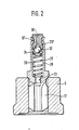
- FIG. 2 shows a second exemplary embodiment of the pressure valve with respect to its essential parts which differ from FIG. 1.
- the plug 29 ′ has an annular groove 37 on its cylindrical outer surface.
- This annular groove allows, in the case of a thin design of the wall of the guide pin 28 in the region of the longitudinal bore, to determine the press-in depth of the plug 29 'after adjustment, so that the plug is held not only by frictional engagement but also by positive engagement.
- the deformation can be done with a rolling or flanging tool.
- Flanks for positive locking can of course also be realized in another form. So the stopper z. B. also have several grooves or be embraced on its end faces.
Landscapes
- Engineering & Computer Science (AREA)
- Chemical & Material Sciences (AREA)
- Combustion & Propulsion (AREA)
- Mechanical Engineering (AREA)
- General Engineering & Computer Science (AREA)
- Fuel-Injection Apparatus (AREA)
Abstract
Description
- Die Erfindung geht von einem Druckventil nach der Gattung des Hauptanspruchs aus. Ein solches durch die DE-OS 32 02 405 bekanntes Druckventil weist ein Ventilschließglied auf, dem auf der Seite der Druckfeder eine Kappe aufgesetzt ist, innerhalb der sich das Schließglied des Rückschlagventils und dessen Rückstellfeder befinden. Diese aufgesetzte Kappe umgreift ein zapfenförmiges Teil des Ventilschließglieds und besitzt mit diesem zusammen eine Schnappverbindung. Im Betrieb eines solchen Ventils hat es sich jedoch gezeigt, daß die aufgesetzte Kappe, die genauso wie das Ventilschließglied des Rückschlagventils von den Drücken der reflektierten Druckwellen beaufschlagt wird, Kraftstoff an seiner Verbindung mit dem Ventilschließglied durchläßt, sofern diese Verbindung nicht völlig dicht gestaltet ist. Die dort durchfließende Kraftstoffmenge beeinflußt den einzustellenden Standdruck in der Kraftstofförderleitung zwischen Druckventil und Einspritzstelle insbesondere auch dann, wenn nach dem Erreichen des gewollten Standdruckes das Rückschlagventil beständig in Schließstellung ist. Das führt zu Streuungen und Fehlern bezüglich der Einspritzmenge. Es wurde weiterhin der Vorschlag gemacht, die aufgesetzte Kappe derart dicht mit dem Ventilschließglied zu Verbinden, indem die Kappe mit einem Elektronenschweißverfahren angeschweißt wird. Dies zieht jedoch erhebliche Herstellungskosten nach sich. Das bekannte Druckventil hat ferner den Nachteil, daß der gewünschte Standdruck des Rückschlagventils mit Hilfe von Zwischenscheiben eingestellt werden muß, die zwischen Rückstellfeder und Auflage eingelegt werden müssen. Auch dieses erfordert einen kostspieligen Montage- und Einstellaufwand.
- Das erfindungsgemäße Druckventil mit den kennzeichnenden Merkmalen des Hauptanspruchs hat demgegenüber den Vorteil, daß das Ventilschließglied einen äußerst einfachen Aufbau aufweist, daß eine kompliziert geformte das Ventilschließglied übergreifende Kappe entfällt und daß vor allen Dingen der Standdruck des Rückschlagventils kontinuierlich verstellbar und justierbar ist. Damit ergeben sich erheblich günstigere Fertigungskosten bei einer sicheren Funktion des Rückschlagventils, geringer Masse des Ventilschließgliedes und genauester Einstellmöglichkeit.
- Durch die in den Unteransprüchen aufgeführten Maßnahmen ist eine vorteilhafte Weiterbildung der im Hauptanspruch gekennzeichneten Lösung gegeben.
- Zwei Ausführungsbeispieß der Erfindung ist in der Zeichnung dargestellt und wird im folgenden näher beschrieben.
- Die Figur zeigt einen Längsschnitt durch ein Druckventil 1, das in das Gehäuse 2 einer nicht weiter dargestellten Kraftstoffeinspritzpumpe eingeschraubt ist und in einer Förderleitung 4 zwischen dem nicht dargestellten Pumpenarbeitsraum der Kraftstoffeinspritzpumpe und einem Einspritzventil 3 der zu versorgenden, nicht dargestellten Brennkraftmaschine sitzt. Das Druckventil weist dabei einen Anschlußstutzen 5 auf, der in eine Gewindebohrung 7 des Gehäuses 2 eingeschraubt ist. Der Anschlußstutzen besitzt eine axiale zylindrische Ausnehmung 8, die zur Einschraubseite hin offen ist und im wesentlichen die Form einer Sackbohrung hat. Koaxial zur zylindrischen Ausnehmung 8 geht von dieser eine Anschlußbohrung 6 ab, die in einem Anschlußnippel 11 des Anschlußstutzens mündet und die Ausnehmung 8 mit der Förderleitung 4 verbindet.
- Vom pumpenseitigen Ende her ist in die axiale Ausnehmung 8 ein rohrförmiger Ventilkörper 9 eingesetzt, der an seinem pumpenseitigen Ende einen Bund 10 aufweist, über den er durch die pumpenseitige Stirnseite 11 des Anschlußstutzens an einer Schulter 12 der Gewindebohrung 7 gehalten wird. Vom pumpenseitigen Ende der Gewindebohrung 7 führt die Förderleitung 4 zum Pumpenarbeitsraum. Am in die axiale Ausnehmung 8 ragenden stirnseitigen Ende weist der rohrförmige Ventilkörper einen Ventilsitz 14 auf, auf dem eine kegelförmige Dichtfläche 15 eines Ventilschließgliedes 16 des Druckventils zur Anlage kommt. Das Ventilschließglied weist in bekannter Weise flügelförmige Führungsflächen 17 auf, die in der Innenbohrung 19 des Ventilkörpers 9 geführt werden und zwischen denen Kraftstoff zum Ventilsitz hin durchtreten kann. Auf einer in den anschlußbohrungsseitigenTeil der Ausnehmung 8 ragenden Schulter 22 des Ventilschließglieds greift eine Druckfeder 20 an, die sich andererseits über einen Federteller 21 am anschlußbohrungsseitigen Ende der Ausnehmung 8 abstützt.
- Das Ventilschließglied 16 weist ferner einen Längskanal 23 auf, der pumpenseitig über eine Querbohrung 24 mit der Innenbohrung 19 verbunden ist und andererseits in eine zylindrische Längsbohrung 26 von größerem Durchmesser mündet, die sich im Bereich eines Führungszapfens 28 befindet, der sich im Anschluß an die Schulter 22 in die axiale Ausnehmung 8 erstreckt und auch zur Führung der Druckfeder 20 dient. Stirnseitig ist die Längsbohrung 26 durch einen Stopfen 29, der dort eingepreßt ist, verschlossen. Der Stopfen weist dabei eine Durchtrittsöffnung 30 auf, die sich zum Innern der Längsbohrung 26 zu einem Ventilsitz 31 erweitert, der der Anlage eines kugelförmigen Schließgliedes 32 eines Rückschlagventils 33 dient. Das Schließglied 32 ist in einem Federteller 34 gelagert, zwischen dem und dem Ende der Längsbohrung 22 eine Rückstellfeder 35 eingespannt ist.
- Wird beim Betrieb einer Kraftstoffeinspritzpumpe, in die das oben beschriebene Druckventil eingebaut ist, Kraftstoff zur Brennkraftmaschine gefördert, so wird unter dem Druck des über die Förderleitung 4 zugeführten Kraftstoffes das Ventilschließglied 16 geöffnet. Am Ende der Kraftstofförderung kehrt das Ventilschließglied zu seinem Ventilsitz 14 zurück. Zugleich schließt das Einspritzventil am Ende der Förderleitung. Im Anschluß an dieses schlagartige Unterbrechen der Förderung laufen in dem eingeschlossenen Volumen zwischen Druckventil und Einspritzventil Druckwellen hin und her, die in der Lage sind, das Einspritzventil zu einem späteren Zeitpunkt nochmals kurzzeitig zu öffnen. Durch das Rückschlagventil kann jedoch das Druckniveau in der Förderleitung auch nach Schließen des Ventilschließgliedes abgebaut werden, und zwar auf einem Standdruck, der durch die Vorspannung der Rückstellfeder des Rückschlagventils bestimmt ist. Mit der oben beschriebenen Anordnung läßt sich nun der Standdruck des Rückschlagventils äußerst genau durch entsprechend mehr oder weniger weites Einpressen des Stopfens 29 einstellen. Es entfällt hier die Notwendigkeit, in Abstufungen Unterlegscheiben zwischen der Rückstellfeder und ihrer Auflage am Ventilschließglied einzubringen und nach diesem Vorgang den Öffnungsdruck nochmals zu messen, bis der gewünschte Wert erreicht ist. Durch die beschriebene Gestaltung wird nach dem Schließen des Rückschlagventils jegliche Verbindung von der Druckseite in der Förderdruckleitung 4 zur pumpenseitigen Förderleitung 4 unterbrochen. Der Längskanal 23 ist dicht gegenüber die axiale zylindrische Ausnehmung verschlossen. Das beschriebene Druckventil läßt sich in sehr einfacher Weise hergestellen mit nur geringem Mehraufwand gegenüber.einem Druckventil ohne Rückschlagventil.
- Ein zweites Ausführungsbeispiel des Druckventils bezüglich seiner wesentlichen von Figur 1 abweichenden Teile zeigt Figur 2. Dort weist der Stopfen 29' eine Ringnut 37 an seiner zylindrischen Mantelfläche auf. Diese Ringnut erlaubt es, bei dünner Ausgestaltung der Wand des Führungszapfens 28 im Bereich der Längsbohrung die Einpreßtiefe des Stopfens 29' nach erfolgter Justierung festzulegen, so daß der Stopfen nicht allein durch Reibschluß sondern auch durch Formschluß gehalten wird. Die Verformung kann mit einem Roll- oder Bördelwerkzeug erfolgen. Flanken für den Formschluß können natürlich auch in anderer Form verwirklicht werden. So kann der Stopfen z. B. auch mehrere Rillen aufweisen oder an seinen Stirnseiten umfaßt werden.
Claims (5)
Applications Claiming Priority (4)
| Application Number | Priority Date | Filing Date | Title |
|---|---|---|---|
| DE3341576 | 1983-11-17 | ||
| DE3341576 | 1983-11-17 | ||
| DE3422017 | 1984-06-14 | ||
| DE19843422017 DE3422017A1 (de) | 1983-11-17 | 1984-06-14 | Druckventil fuer kraftstoffeinspritzpumpen |
Publications (3)
| Publication Number | Publication Date |
|---|---|
| EP0143296A2 true EP0143296A2 (de) | 1985-06-05 |
| EP0143296A3 EP0143296A3 (en) | 1985-07-03 |
| EP0143296B1 EP0143296B1 (de) | 1988-01-27 |
Family
ID=25815692
Family Applications (1)
| Application Number | Title | Priority Date | Filing Date |
|---|---|---|---|
| EP19840112337 Expired EP0143296B1 (de) | 1983-11-17 | 1984-10-13 | Druckventil für Kraftstoffeinspritzpumpen |
Country Status (3)
| Country | Link |
|---|---|
| EP (1) | EP0143296B1 (de) |
| JP (1) | JPS60119366A (de) |
| DE (2) | DE3422017A1 (de) |
Cited By (4)
| Publication number | Priority date | Publication date | Assignee | Title |
|---|---|---|---|---|
| GB2202595A (en) * | 1987-03-27 | 1988-09-28 | Diesel Kiki Co | Pressure-relieving delivery valve for fuel injection system |
| EP0383075A1 (de) * | 1989-02-15 | 1990-08-22 | Robert Bosch Gmbh | Gleichdruckentlastungsventil für Kraftstoffeinspritzanlagen |
| FR2680389A1 (fr) * | 1991-08-14 | 1993-02-19 | Bosch Gmbh Robert | Soupape de decharge a equipression pour appareils d'injection de carburant, a monter dans la conduite de refoulement d'une pompe d'injection et l'injecteur. |
| US9168498B2 (en) | 2005-11-04 | 2015-10-27 | Abbvie Deutschland Gmbh & Co Kg | Method and device for producing very fine particles and coating such particles |
Families Citing this family (15)
| Publication number | Priority date | Publication date | Assignee | Title |
|---|---|---|---|---|
| JPS62243965A (ja) * | 1986-04-12 | 1987-10-24 | Diesel Kiki Co Ltd | 等圧弁 |
| JPH059499Y2 (de) * | 1988-01-18 | 1993-03-09 | ||
| JP2841510B2 (ja) * | 1989-08-02 | 1998-12-24 | 株式会社デンソー | 燃料噴射ポンプ |
| JP2636483B2 (ja) * | 1990-09-12 | 1997-07-30 | 株式会社デンソー | 燃料噴射ポンプ用吐出弁 |
| DE4037465A1 (de) * | 1990-10-31 | 1992-05-07 | Daimler Benz Ag | Kraftstoffeinspritzpumpe fuer brennkraftmaschinen |
| JPH0693886A (ja) * | 1992-07-31 | 1994-04-05 | Nippondenso Co Ltd | 燃料噴射ポンプ用遠心力ガバナ |
| JP4998837B2 (ja) | 2009-12-10 | 2012-08-15 | 株式会社デンソー | 高圧ポンプ |
| US9181944B2 (en) | 2011-03-31 | 2015-11-10 | Denso Corporation | High pressure pump having unitary discharge and relief valve |
| JP5553176B2 (ja) * | 2011-08-31 | 2014-07-16 | 株式会社デンソー | 高圧ポンプ |
| CN103437930B (zh) * | 2013-08-13 | 2018-05-29 | 南京威孚金宁有限公司 | 等压阀性能的控制方法 |
| JP5920636B2 (ja) * | 2013-09-13 | 2016-05-18 | 株式会社デンソー | 高圧ポンプ |
| JP5644926B2 (ja) * | 2013-10-11 | 2014-12-24 | 株式会社デンソー | 高圧ポンプ |
| DE102014208891B3 (de) | 2014-05-12 | 2015-09-24 | Continental Automotive Gmbh | Druckbegrenzungsventil und Bauteil für ein Kraftstoffeinspritzsystem sowie Verfahren zur Herstellung eines Druckbegrenzungsventils |
| CN108317031B (zh) * | 2018-02-09 | 2020-07-17 | 中国第一汽车股份有限公司 | 燃料供给保持阀 |
| GB2620930B (en) * | 2022-07-25 | 2024-12-25 | Phinia Delphi Luxembourg Sarl | Pump |
Family Cites Families (3)
| Publication number | Priority date | Publication date | Assignee | Title |
|---|---|---|---|---|
| GB399858A (en) * | 1932-04-12 | 1933-10-12 | Bryce Ltd | Improvements in and relating to delivery valves of reciprocating pumps |
| GB566957A (en) * | 1942-04-01 | 1945-01-22 | Bendix Aviat Corp | Improvement in fuel injection apparatus |
| JPS56115849A (en) * | 1980-02-15 | 1981-09-11 | Nippon Denso Co Ltd | Fuel injection pump for internal combustion engine |
-
1984
- 1984-06-14 DE DE19843422017 patent/DE3422017A1/de not_active Withdrawn
- 1984-10-13 EP EP19840112337 patent/EP0143296B1/de not_active Expired
- 1984-10-13 DE DE8484112337T patent/DE3469052D1/de not_active Expired
- 1984-11-13 JP JP59237718A patent/JPS60119366A/ja active Granted
Cited By (5)
| Publication number | Priority date | Publication date | Assignee | Title |
|---|---|---|---|---|
| GB2202595A (en) * | 1987-03-27 | 1988-09-28 | Diesel Kiki Co | Pressure-relieving delivery valve for fuel injection system |
| GB2202595B (en) * | 1987-03-27 | 1991-03-27 | Diesel Kiki Co | Valve structure of a fuel discharge valve in a fuel injection pump |
| EP0383075A1 (de) * | 1989-02-15 | 1990-08-22 | Robert Bosch Gmbh | Gleichdruckentlastungsventil für Kraftstoffeinspritzanlagen |
| FR2680389A1 (fr) * | 1991-08-14 | 1993-02-19 | Bosch Gmbh Robert | Soupape de decharge a equipression pour appareils d'injection de carburant, a monter dans la conduite de refoulement d'une pompe d'injection et l'injecteur. |
| US9168498B2 (en) | 2005-11-04 | 2015-10-27 | Abbvie Deutschland Gmbh & Co Kg | Method and device for producing very fine particles and coating such particles |
Also Published As
| Publication number | Publication date |
|---|---|
| JPH0552429B2 (de) | 1993-08-05 |
| EP0143296A3 (en) | 1985-07-03 |
| DE3469052D1 (en) | 1988-03-03 |
| DE3422017A1 (de) | 1985-05-30 |
| JPS60119366A (ja) | 1985-06-26 |
| EP0143296B1 (de) | 1988-01-27 |
Similar Documents
| Publication | Publication Date | Title |
|---|---|---|
| EP0143296A2 (de) | Druckventil für Kraftstoffeinspritzpumpen | |
| DE3341575C2 (de) | Druckventil für Kraftstoffeinspritzpumpen | |
| DE2710216A1 (de) | Kraftstoffeinspritzduese | |
| EP0147591A2 (de) | Druckventil für Kraftstoffeinspritzpumpen | |
| EP0302068B1 (de) | Rückschlagventil | |
| DE2903907A1 (de) | Druckregler fuer einspritzanlagen bei verbrennungsmotoren | |
| EP0390881B1 (de) | Druckventil | |
| DE69107405T2 (de) | Hochdruck-Dichtungssystem für das Steuerventil eines elektromagnetischen Brennstoffeinspritzventils für Verbrennungsmotoren. | |
| DE4413190A1 (de) | Druckbegrenzungsventil und Verfahren zum Einstellen eines Öffnungsdruckes an dem Druckbegrenzungsventil | |
| DE3307735C2 (de) | Vorrichtung zur Ölversorgung einer Kraftstoffeinspritzpumpe | |
| CH686845A5 (de) | Steueranordnung fuer ein Einspritzventil fuer Verbrennungskraftmaschinen. | |
| EP0626303B1 (de) | Ventilanordnung | |
| DE1805024C2 (de) | Aus einer Baueinheit aus Einspritzpumpe und Einspritzventil bestehende Kraftstoffeinspritzvorrichtung für Brennkraftmaschinen | |
| DE1526637C3 (de) | ||
| DE7925377U1 (de) | Kraftstoffeinspritzpumpe fuer brennkraftmaschinen | |
| DE1526637B2 (de) | Brennstoffeinspritzvorrichtung fuer brennkraftmaschinen | |
| DE19839821A1 (de) | Rückschlagventil und Ventilsitzkörper | |
| DE19940558C2 (de) | Vorrichtung zum Verzögern des Auslenkens der Düsennadel eines Kraftstoffeinspritzventils | |
| DE4240303C2 (de) | Druckventil | |
| EP0698182A1 (de) | Einspritzdüse für brennkraftmaschinen | |
| DE3725566A1 (de) | Ventilaufbau | |
| DE3325451A1 (de) | Kraftstoffeinlassventil fuer brennkraftmaschinen | |
| DE8333049U1 (de) | Druckventil fuer kraftstoffeinspritzpumpen | |
| DE3912106C2 (de) | Kraftstoffeinspritzvorrichtung | |
| DE1526637C2 (de) | Brennstoffeinspritzvorrichtung für Brennkraftmaschinen |
Legal Events
| Date | Code | Title | Description |
|---|---|---|---|
| PUAI | Public reference made under article 153(3) epc to a published international application that has entered the european phase |
Free format text: ORIGINAL CODE: 0009012 |
|
| PUAL | Search report despatched |
Free format text: ORIGINAL CODE: 0009013 |
|
| 17P | Request for examination filed |
Effective date: 19841013 |
|
| AK | Designated contracting states |
Designated state(s): DE FR GB |
|
| AK | Designated contracting states |
Designated state(s): DE FR GB |
|
| 17Q | First examination report despatched |
Effective date: 19860220 |
|
| GRAA | (expected) grant |
Free format text: ORIGINAL CODE: 0009210 |
|
| AK | Designated contracting states |
Kind code of ref document: B1 Designated state(s): DE FR GB |
|
| REF | Corresponds to: |
Ref document number: 3469052 Country of ref document: DE Date of ref document: 19880303 |
|
| GBT | Gb: translation of ep patent filed (gb section 77(6)(a)/1977) | ||
| ET | Fr: translation filed | ||
| PLBE | No opposition filed within time limit |
Free format text: ORIGINAL CODE: 0009261 |
|
| STAA | Information on the status of an ep patent application or granted ep patent |
Free format text: STATUS: NO OPPOSITION FILED WITHIN TIME LIMIT |
|
| 26N | No opposition filed | ||
| REG | Reference to a national code |
Ref country code: GB Ref legal event code: IF02 |
|
| PGFP | Annual fee paid to national office [announced via postgrant information from national office to epo] |
Ref country code: GB Payment date: 20020919 Year of fee payment: 19 |
|
| PGFP | Annual fee paid to national office [announced via postgrant information from national office to epo] |
Ref country code: FR Payment date: 20021018 Year of fee payment: 19 |
|
| PGFP | Annual fee paid to national office [announced via postgrant information from national office to epo] |
Ref country code: DE Payment date: 20021127 Year of fee payment: 19 |
|
| PG25 | Lapsed in a contracting state [announced via postgrant information from national office to epo] |
Ref country code: GB Free format text: LAPSE BECAUSE OF NON-PAYMENT OF DUE FEES Effective date: 20031013 |
|
| PG25 | Lapsed in a contracting state [announced via postgrant information from national office to epo] |
Ref country code: DE Free format text: LAPSE BECAUSE OF NON-PAYMENT OF DUE FEES Effective date: 20040501 |
|
| GBPC | Gb: european patent ceased through non-payment of renewal fee |
Effective date: 20031013 |
|
| PG25 | Lapsed in a contracting state [announced via postgrant information from national office to epo] |
Ref country code: FR Free format text: LAPSE BECAUSE OF NON-PAYMENT OF DUE FEES Effective date: 20040630 |
|
| REG | Reference to a national code |
Ref country code: FR Ref legal event code: ST |