EP0142656B1 - Vorrichtung zum Binden eines langgestreckten Gegenstandes, beispielsweise eines Kabelbaums - Google Patents
Vorrichtung zum Binden eines langgestreckten Gegenstandes, beispielsweise eines Kabelbaums Download PDFInfo
- Publication number
- EP0142656B1 EP0142656B1 EP84110841A EP84110841A EP0142656B1 EP 0142656 B1 EP0142656 B1 EP 0142656B1 EP 84110841 A EP84110841 A EP 84110841A EP 84110841 A EP84110841 A EP 84110841A EP 0142656 B1 EP0142656 B1 EP 0142656B1
- Authority
- EP
- European Patent Office
- Prior art keywords
- pin
- band
- lock
- bore
- lock body
- Prior art date
- Legal status (The legal status is an assumption and is not a legal conclusion. Google has not performed a legal analysis and makes no representation as to the accuracy of the status listed.)
- Expired
Links
- 238000005728 strengthening Methods 0.000 claims 1
- 239000011324 bead Substances 0.000 description 5
- 230000003014 reinforcing effect Effects 0.000 description 5
- 239000004952 Polyamide Substances 0.000 description 4
- 239000000463 material Substances 0.000 description 4
- 229920002647 polyamide Polymers 0.000 description 4
- 230000000694 effects Effects 0.000 description 2
- 230000005489 elastic deformation Effects 0.000 description 2
- 230000008719 thickening Effects 0.000 description 2
- 101100008048 Caenorhabditis elegans cut-4 gene Proteins 0.000 description 1
- 238000010521 absorption reaction Methods 0.000 description 1
- 230000001154 acute effect Effects 0.000 description 1
- 230000005540 biological transmission Effects 0.000 description 1
- 238000005553 drilling Methods 0.000 description 1
- 239000003365 glass fiber Substances 0.000 description 1
- 230000002093 peripheral effect Effects 0.000 description 1
- 239000004033 plastic Substances 0.000 description 1
- 230000000717 retained effect Effects 0.000 description 1
Images
Classifications
-
- B—PERFORMING OPERATIONS; TRANSPORTING
- B65—CONVEYING; PACKING; STORING; HANDLING THIN OR FILAMENTARY MATERIAL
- B65D—CONTAINERS FOR STORAGE OR TRANSPORT OF ARTICLES OR MATERIALS, e.g. BAGS, BARRELS, BOTTLES, BOXES, CANS, CARTONS, CRATES, DRUMS, JARS, TANKS, HOPPERS, FORWARDING CONTAINERS; ACCESSORIES, CLOSURES, OR FITTINGS THEREFOR; PACKAGING ELEMENTS; PACKAGES
- B65D63/00—Flexible elongated elements, e.g. straps, for bundling or supporting articles
- B65D63/10—Non-metallic straps, tapes, or bands; Filamentary elements, e.g. strings, threads or wires; Joints between ends thereof
- B65D63/14—Joints produced by application of separate securing members
-
- F—MECHANICAL ENGINEERING; LIGHTING; HEATING; WEAPONS; BLASTING
- F16—ENGINEERING ELEMENTS AND UNITS; GENERAL MEASURES FOR PRODUCING AND MAINTAINING EFFECTIVE FUNCTIONING OF MACHINES OR INSTALLATIONS; THERMAL INSULATION IN GENERAL
- F16L—PIPES; JOINTS OR FITTINGS FOR PIPES; SUPPORTS FOR PIPES, CABLES OR PROTECTIVE TUBING; MEANS FOR THERMAL INSULATION IN GENERAL
- F16L3/00—Supports for pipes, cables or protective tubing, e.g. hangers, holders, clamps, cleats, clips, brackets
- F16L3/14—Hangers in the form of bands or chains
-
- Y—GENERAL TAGGING OF NEW TECHNOLOGICAL DEVELOPMENTS; GENERAL TAGGING OF CROSS-SECTIONAL TECHNOLOGIES SPANNING OVER SEVERAL SECTIONS OF THE IPC; TECHNICAL SUBJECTS COVERED BY FORMER USPC CROSS-REFERENCE ART COLLECTIONS [XRACs] AND DIGESTS
- Y10—TECHNICAL SUBJECTS COVERED BY FORMER USPC
- Y10T—TECHNICAL SUBJECTS COVERED BY FORMER US CLASSIFICATION
- Y10T24/00—Buckles, buttons, clasps, etc.
- Y10T24/14—Bale and package ties, hose clamps
- Y10T24/1457—Metal bands
- Y10T24/1459—Separate connections
- Y10T24/1473—Wedging parts
-
- Y—GENERAL TAGGING OF NEW TECHNOLOGICAL DEVELOPMENTS; GENERAL TAGGING OF CROSS-SECTIONAL TECHNOLOGIES SPANNING OVER SEVERAL SECTIONS OF THE IPC; TECHNICAL SUBJECTS COVERED BY FORMER USPC CROSS-REFERENCE ART COLLECTIONS [XRACs] AND DIGESTS
- Y10—TECHNICAL SUBJECTS COVERED BY FORMER USPC
- Y10T—TECHNICAL SUBJECTS COVERED BY FORMER US CLASSIFICATION
- Y10T24/00—Buckles, buttons, clasps, etc.
- Y10T24/14—Bale and package ties, hose clamps
- Y10T24/1498—Plastic band
-
- Y—GENERAL TAGGING OF NEW TECHNOLOGICAL DEVELOPMENTS; GENERAL TAGGING OF CROSS-SECTIONAL TECHNOLOGIES SPANNING OVER SEVERAL SECTIONS OF THE IPC; TECHNICAL SUBJECTS COVERED BY FORMER USPC CROSS-REFERENCE ART COLLECTIONS [XRACs] AND DIGESTS
- Y10—TECHNICAL SUBJECTS COVERED BY FORMER USPC
- Y10T—TECHNICAL SUBJECTS COVERED BY FORMER US CLASSIFICATION
- Y10T292/00—Closure fasteners
- Y10T292/48—Seals
- Y10T292/491—Distorted shackle
-
- Y—GENERAL TAGGING OF NEW TECHNOLOGICAL DEVELOPMENTS; GENERAL TAGGING OF CROSS-SECTIONAL TECHNOLOGIES SPANNING OVER SEVERAL SECTIONS OF THE IPC; TECHNICAL SUBJECTS COVERED BY FORMER USPC CROSS-REFERENCE ART COLLECTIONS [XRACs] AND DIGESTS
- Y10—TECHNICAL SUBJECTS COVERED BY FORMER USPC
- Y10T—TECHNICAL SUBJECTS COVERED BY FORMER US CLASSIFICATION
- Y10T292/00—Closure fasteners
- Y10T292/48—Seals
- Y10T292/506—Rigid disk, distorted shackle
Definitions
- the invention relates to a device for binding an elongated object, for example a cable bundle, with a band to be tensioned around the object and a lock connecting the band ends, which has a through opening for at least one band end and a transverse bore that passes through the contains in the through-hole band to be driven pin, the pin and the bore are provided with the pin in its end position securing, cooperating projections and recesses.
- the tape is shaped like a potty around the end of the pin when the pin is driven through.
- the pin is secured in the closed position in that it is crimped like a rivet head at its preceding end together with the surrounding deep-drawn tape within an enlarged part of the bore and thus assumes a diameter that is larger than the diameter in the part behind it Drilling.
- the band and the pin is usually somewhat resilient, for example in the case of production from polyamide, the thickening is carried out vigorously in practice, since there is otherwise the risk that the pin will slide back under high band tension with a corresponding expansion of the lock body.
- irregularities can occur when the strap closure is closed, which can result in the thickening of the pin being less severe than is actually desired, the risk cannot be ruled out that a closure sometimes has insufficient strength due to insufficient pin deformation.
- the invention has for its object to provide a device of the type mentioned, which has a higher locking security, in particular regardless of the care with which the closure was carried out.
- the solution according to the invention is that the pin and the bore have on their side facing the object to be bound against the release direction of the pin one behind the other locking edges which are arranged so that they are held more securely in engagement with increasing tape tension.
- the invention is based on the idea that in this arrangement the pin is pressed by the band forces on the side of the bore facing the object to be bound and that a locking connection provided on this side is therefore not only by the elastic forces of the material used but rather by the Band forces are held together.
- the lock body is deformed under the belt tension in the area of the locking edges, the more secure the mutual engagement of the locking edges.
- Such a deformation can primarily be attributed to the fact that the lock body is exposed to a tension widening it due to the ends of the strap which diverge from it in the opposite direction.
- the lock is reinforced on the side of the object to be bound, preferably by means of ribs provided on the object side of the lock body on the object side.
- the end of the band to be secured in the lock becomes almost 90 ° when it enters the through opening redirected. Because of the short distances, the tensile stresses occurring on the outside of the bend also have an effect in the area in which it is deformed by the pin, in that they can amplify the forces which force the pin in the release direction.
- the deflection angle of the band is reduced when it enters the through-openings in that the contact surface of the lock body, which bears directly on the object to be bound or via the band, mediates an angle of more to the direction of the through-opening than 90 ° on the side of the band entering the through opening.
- the aforementioned reinforcing ribs are expediently used to form this contact surface.
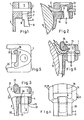
- the lock body 1 of the embodiment according to FIGS. 1 and 2 which is to be presented in a square shape, has a flat through opening 2 of constant cross section, which is similar to that of the band 3, which is made in one piece with the lock body 1, for example from polyamide.
- the lock body 1 Transversely to the through opening 2, the lock body 1 contains a bore, the lower section 4 of which has a somewhat narrower cross section than its upper section 5.
- the pin 6 is inserted with its head 7 into the bore section 4 approximately fittingly, so that it is retained therein due to its friction.
- the foot 8 of the pin 6 is offset from the head 7 at 9 steps.
- the pen is narrower than the tape in the direction transverse to the plane of the drawing.
- the band 3 is wrapped around the object 10 to be bound; its end 11 is guided through the through opening 2; there is tension; then the pin 6 is pushed into the lock body by a force acting in the direction of the arrow 12.
- the band 3 is drawn in a potty-shaped manner around the head 7 of the pin 6 in the region 13, so that it encloses the head 7 of the pin 6 on five sides.
- the pin is pressed into the lock body until its level 9 reaches behind the level 14 of the lock body. Due to the tension in the band 3 indicated by arrows, the pin 6 is pulled to the left in FIG. 2, so that the stages 9 and 14 fully engage with one another.
- the securing forces are therefore always greater than those forces of the band 3, which act on the pin in the release direction (against the direction of arrow 12).
- the lock body 1 has an approximately quadratic outer shape. It is integrally connected to it on its underside on its edge of the band 3 facing the object 10 to be bound, said edge being composed of two bead-shaped edges 20 and a thinner middle part 21.
- the bead edges 20 project in cross section on the side facing the object to be bound. They pass on the lock body to the side of the through opening 2 into reinforcing ribs 22, which form the contact surfaces 23 with which the lock body rests on the surface of the object 10 to be bound.
- the direction of these contact surfaces 23 includes an angle with the direction of the through opening 2, which is greater than 90 ° on the side of the band to be inserted into the through opening, so that, as can be seen in FIG. 6, a curvature of less than 90 ° suffers when entering the through opening.
- the tensile forces exerted by the band 3 from its end integrally connected to the lock on the lock body thanks to these reinforcing ribs, are not only introduced into that part of the lock body that lies below the through opening 2, but also into the part above it 24, which can be additionally strengthened by a bead 25 so as to withstand deformation under the tension of the strip end entering the passage opening 2.
- the bore is concentrically cylindrical, the upper section 5 having a larger diameter for receiving the deep-drawn region 13 of the band 3.
- the pin has a concentrically cylindrical shape over its entire length, its diameter being the same as that of the lower section 4 of the bore.
- it has an annular projection 26 which, at least on its lower side, forms a latching edge or stop surface 27 which extends at right angles to the other pin surface. It is expedient, as shown, to have the same design on its upper and lower sides, so that the pin does not have to be oriented in a certain way when it is inserted into the bore.
- the Ring projection 26 is designed so that it can be driven in the direction of arrow 12 through the lower section 4 of the bore with elastic deformation of the pin and the lock body until the stop surface 27 lies above the opposite stop surface 28 of the lock body in the through opening 2.
- the annular projection 26 with the stop surface 27 forms in cooperation with the bore cut 4 and the stop surface 28 delimiting it, a latching connection, which opposes a release movement of the pin against the direction of the arrow 12 considerable resistance, which only by deformation of the Abbey and / or the castle can be overcome.
- this is pulled up a little at an acute angle against the release direction of the pin 6, as can be seen in FIG.
- the reinforcing ribs 22 and the bead 25 and generally the deformation-resistant design of the lock body on its side facing the object 10 to be bound also help to keep the engagement conditions of the abutment surfaces 27, 28 largely free of deformations even under conditions of heavy use, so that the Intervention of the stop surfaces is not endangered.
- the directional projection can be replaced by a plurality of projections, with the number and arrangement of these projections only having to ensure that at least one projection must be located in the peripheral region of the pin 6 which points to the left in FIG. 6 and in which the Pin circumference is pulled against the circumference of the hole by pulling the tape.
- the surface 23 of the ribs 22 which is in contact with the object 10 to be bound should continuously merge into the surface of the bead edges 20 of the band 3, as can be seen in FIG. 3, in order to ensure uniform contact with the object to be bound, and thus to ensure an even power transmission.
- This may be necessary, for example, if the object to be bound is a flexible sleeve that is to be tightly adapted to a nozzle over its entire circumference. This also prevents the band 3 from being strongly bent in the region in which it integrally merges into the lock body 1, which could impair both the strength of the band and the mechanical properties of the lock body.
- this can be concavely curved in accordance with the average curvature of the objects to be bound, as can be seen in FIG. 3.
- the pin 6 can be made of more resistant material so that the ring projection is not damaged when the pin is pressed into the lock body. If the lock body is made of polyamide, the pin can for example consist of glass fiber reinforced polyamide.
- the ring projection on its leading side and / or the input side of the bore can also be provided with a chamfer or chamfer in order to facilitate the elastic deformation when the pin is pressed in.
Landscapes
- Engineering & Computer Science (AREA)
- Mechanical Engineering (AREA)
- General Engineering & Computer Science (AREA)
- Package Frames And Binding Bands (AREA)
- Clamps And Clips (AREA)
- Basic Packing Technique (AREA)
Applications Claiming Priority (2)
| Application Number | Priority Date | Filing Date | Title |
|---|---|---|---|
| DE8327158U DE8327158U1 (de) | 1983-09-21 | 1983-09-21 | Vorrichtung zum Binden eines langestreckten Gegenstands wie eines Kabelbuendels |
| DE8327158U | 1983-09-21 |
Publications (2)
| Publication Number | Publication Date |
|---|---|
| EP0142656A1 EP0142656A1 (de) | 1985-05-29 |
| EP0142656B1 true EP0142656B1 (de) | 1987-02-04 |
Family
ID=6757257
Family Applications (1)
| Application Number | Title | Priority Date | Filing Date |
|---|---|---|---|
| EP84110841A Expired EP0142656B1 (de) | 1983-09-21 | 1984-09-12 | Vorrichtung zum Binden eines langgestreckten Gegenstandes, beispielsweise eines Kabelbaums |
Country Status (7)
| Country | Link |
|---|---|
| US (1) | US4607414A (enExample) |
| EP (1) | EP0142656B1 (enExample) |
| JP (1) | JPS6099809A (enExample) |
| DE (2) | DE8327158U1 (enExample) |
| ES (1) | ES281519Y (enExample) |
| HK (1) | HK26588A (enExample) |
| SG (1) | SG43487G (enExample) |
Families Citing this family (3)
| Publication number | Priority date | Publication date | Assignee | Title |
|---|---|---|---|---|
| US4883295A (en) * | 1985-09-06 | 1989-11-28 | Kesselman David A | Tamper deterrent assembly |
| US5743574A (en) * | 1996-12-06 | 1998-04-28 | Pci-Products Company International, Inc. | One-piece pierce-lock double-engagement cable-seal |
| US20240360922A1 (en) | 2023-04-28 | 2024-10-31 | Hellermanntyton Corporation | Cable Tie Cradle Mount Fixings |
Family Cites Families (17)
| Publication number | Priority date | Publication date | Assignee | Title |
|---|---|---|---|---|
| US193320A (en) * | 1877-07-24 | Improvement in metallic seals | ||
| US149468A (en) * | 1874-04-07 | Improvement in cotton-bale ties | ||
| US961069A (en) * | 1909-09-21 | 1910-06-07 | John L Carpenter | Seal. |
| US1107935A (en) * | 1912-10-14 | 1914-08-18 | Mechanical Process Mfg Company | Glassware re-forming mechanism. |
| US3015865A (en) * | 1960-05-24 | 1962-01-09 | John J Rapuzzi | Universal inserted ball type buckle |
| US2988391A (en) * | 1960-08-08 | 1961-06-13 | J F Rhodes Co | Injection molded seal device |
| US3107935A (en) * | 1961-11-13 | 1963-10-22 | J F Rhodes Co | Injection molded seal device |
| DE1279801B (de) * | 1963-04-26 | 1968-10-10 | Hellermann Gmbh P | Verfahren und Vorrichtungen zum Binden von Kabelbaeumen od. dgl. mit einem herumgelegten Band, dessen Enden von einem Schloss gehalten werden |
| US3226882A (en) * | 1964-01-02 | 1966-01-04 | Lichtenthaler James Paul | Tree tie |
| US3353227A (en) * | 1965-04-09 | 1967-11-21 | Hellermann Gmbh P | Device for tieing cable harnesses |
| US3457598A (en) * | 1968-08-09 | 1969-07-29 | Thomas & Betts Corp | Self-clinching bundling strap |
| DE2054520A1 (de) * | 1970-11-05 | 1972-05-10 | Hellermann Gmbh P | Vorrichtung und Verfahren zum Binden von Gegenständen wie Kabelbäumen, Installationsleitungen oder dgl |
| DE2608704A1 (de) * | 1976-03-03 | 1977-09-08 | Hellermann Gmbh P | Vorrichtung zum halten von langgestreckten gegenstaenden wie kabelbaeumen |
| JPS5518301U (enExample) * | 1978-07-22 | 1980-02-05 | ||
| FR2486172A1 (fr) * | 1980-07-07 | 1982-01-08 | Seperef | Collier de serrage, notamment pour elements tubulaires |
| GB2081798B (en) * | 1980-07-24 | 1984-06-06 | American Casting & Manufacturi | Improvements in security seals |
| FR2513328A1 (fr) * | 1981-09-23 | 1983-03-25 | Legrand Sa | Collier de serrage |
-
1983
- 1983-09-21 DE DE8327158U patent/DE8327158U1/de not_active Expired
-
1984
- 1984-09-12 EP EP84110841A patent/EP0142656B1/de not_active Expired
- 1984-09-12 DE DE8484110841T patent/DE3462322D1/de not_active Expired
- 1984-09-14 US US06/650,434 patent/US4607414A/en not_active Expired - Lifetime
- 1984-09-19 ES ES1984281519U patent/ES281519Y/es not_active Expired
- 1984-09-21 JP JP59199319A patent/JPS6099809A/ja active Granted
-
1987
- 1987-05-11 SG SG434/87A patent/SG43487G/en unknown
-
1988
- 1988-04-14 HK HK265/88A patent/HK26588A/xx not_active IP Right Cessation
Also Published As
| Publication number | Publication date |
|---|---|
| ES281519U (es) | 1986-01-01 |
| JPS6099809A (ja) | 1985-06-03 |
| EP0142656A1 (de) | 1985-05-29 |
| SG43487G (en) | 1987-11-13 |
| DE8327158U1 (de) | 1983-11-10 |
| JPH057267B2 (enExample) | 1993-01-28 |
| ES281519Y (es) | 1986-07-16 |
| HK26588A (en) | 1988-04-22 |
| DE3462322D1 (en) | 1987-03-12 |
| US4607414A (en) | 1986-08-26 |
Similar Documents
| Publication | Publication Date | Title |
|---|---|---|
| DE2901061C2 (de) | Verschlußplombe | |
| DE3033886C2 (enExample) | ||
| DE3447693A1 (de) | Selbstsperrendes flaches klemmband | |
| DE1926222A1 (de) | Vorrichtung zur loesbaren Verbindung von flexiblen Materialbahnen | |
| EP3602709B1 (de) | Leitungsführungseinrichtung | |
| EP1961094B1 (de) | Befestigungsschiene für einen langgestreckten gegenstand | |
| DE112006000124T5 (de) | Schließe | |
| CH677010A5 (enExample) | ||
| DE2626920A1 (de) | Haken | |
| AT394978B (de) | Reifenkette | |
| WO2009149777A1 (de) | Verkürzungsringgabel zum verkürzen eines kettenstrangs | |
| DE2708538B2 (de) | Verbindung zwischen den Kettengliedern einer Gleiskette | |
| EP0142656B1 (de) | Vorrichtung zum Binden eines langgestreckten Gegenstandes, beispielsweise eines Kabelbaums | |
| EP0130138B1 (de) | Bauteil für Rundgliederketten | |
| CH684293A5 (de) | Verbindungs- und Anschlussstück für Wellrohre. | |
| DE3049066A1 (de) | Kabelband aus flexiblem, hartelastischem kunststoff | |
| DE4410706C2 (de) | Wellenschlauch | |
| DE102017131237A1 (de) | Kabelbinder | |
| EP2059453B1 (de) | Kabelbinder | |
| DE4207565C1 (en) | Releasable arrester for plug connectors, cable tension relief or similar - has deformable arresting spring strip in jaw region of pivotable arresting hook and pin | |
| DE2721357A1 (de) | Abspannklemme | |
| EP1777791A2 (de) | Abschluss- und/oder Verbindungsstück | |
| DE2524631A1 (de) | Kunststoffverschluss fuer spannringe | |
| DE3619809A1 (de) | Kabelbinder | |
| DE574043C (de) | Befestigung fuer Draht- oder Kabelenden, insbesondere fuer Luftfahrzeuge |
Legal Events
| Date | Code | Title | Description |
|---|---|---|---|
| PUAI | Public reference made under article 153(3) epc to a published international application that has entered the european phase |
Free format text: ORIGINAL CODE: 0009012 |
|
| AK | Designated contracting states |
Designated state(s): DE FR GB IT NL SE |
|
| 17P | Request for examination filed |
Effective date: 19850329 |
|
| 17Q | First examination report despatched |
Effective date: 19860117 |
|
| GRAA | (expected) grant |
Free format text: ORIGINAL CODE: 0009210 |
|
| AK | Designated contracting states |
Kind code of ref document: B1 Designated state(s): DE FR GB IT NL SE |
|
| REF | Corresponds to: |
Ref document number: 3462322 Country of ref document: DE Date of ref document: 19870312 |
|
| ITF | It: translation for a ep patent filed | ||
| ET | Fr: translation filed | ||
| PLBE | No opposition filed within time limit |
Free format text: ORIGINAL CODE: 0009261 |
|
| STAA | Information on the status of an ep patent application or granted ep patent |
Free format text: STATUS: NO OPPOSITION FILED WITHIN TIME LIMIT |
|
| 26N | No opposition filed | ||
| ITTA | It: last paid annual fee | ||
| EAL | Se: european patent in force in sweden |
Ref document number: 84110841.8 |
|
| REG | Reference to a national code |
Ref country code: GB Ref legal event code: IF02 |
|
| PGFP | Annual fee paid to national office [announced via postgrant information from national office to epo] |
Ref country code: GB Payment date: 20030821 Year of fee payment: 20 |
|
| PGFP | Annual fee paid to national office [announced via postgrant information from national office to epo] |
Ref country code: NL Payment date: 20030917 Year of fee payment: 20 |
|
| PGFP | Annual fee paid to national office [announced via postgrant information from national office to epo] |
Ref country code: FR Payment date: 20030918 Year of fee payment: 20 |
|
| PGFP | Annual fee paid to national office [announced via postgrant information from national office to epo] |
Ref country code: SE Payment date: 20030923 Year of fee payment: 20 |
|
| PGFP | Annual fee paid to national office [announced via postgrant information from national office to epo] |
Ref country code: DE Payment date: 20031121 Year of fee payment: 20 |
|
| PG25 | Lapsed in a contracting state [announced via postgrant information from national office to epo] |
Ref country code: GB Free format text: LAPSE BECAUSE OF EXPIRATION OF PROTECTION Effective date: 20040911 |
|
| PG25 | Lapsed in a contracting state [announced via postgrant information from national office to epo] |
Ref country code: NL Free format text: LAPSE BECAUSE OF EXPIRATION OF PROTECTION Effective date: 20040912 |
|
| REG | Reference to a national code |
Ref country code: GB Ref legal event code: PE20 |
|
| NLV7 | Nl: ceased due to reaching the maximum lifetime of a patent |
Effective date: 20040912 |
|
| EUG | Se: european patent has lapsed |