EP0140412A1 - Spleissvorrichtungen für das mechanische Spleissen von Textilgarnen, und mechanische Spleissvorrichtung, die derartige Vorrichtungen benutzt - Google Patents
Spleissvorrichtungen für das mechanische Spleissen von Textilgarnen, und mechanische Spleissvorrichtung, die derartige Vorrichtungen benutzt Download PDFInfo
- Publication number
- EP0140412A1 EP0140412A1 EP84201306A EP84201306A EP0140412A1 EP 0140412 A1 EP0140412 A1 EP 0140412A1 EP 84201306 A EP84201306 A EP 84201306A EP 84201306 A EP84201306 A EP 84201306A EP 0140412 A1 EP0140412 A1 EP 0140412A1
- Authority
- EP
- European Patent Office
- Prior art keywords
- yarns
- splicer
- textile yarns
- yarn
- mechanical
- Prior art date
- Legal status (The legal status is an assumption and is not a legal conclusion. Google has not performed a legal analysis and makes no representation as to the accuracy of the status listed.)
- Granted
Links
Images


Classifications
-
- B—PERFORMING OPERATIONS; TRANSPORTING
- B65—CONVEYING; PACKING; STORING; HANDLING THIN OR FILAMENTARY MATERIAL
- B65H—HANDLING THIN OR FILAMENTARY MATERIAL, e.g. SHEETS, WEBS, CABLES
- B65H69/00—Methods of, or devices for, interconnecting successive lengths of material; Knot-tying devices ;Control of the correct working of the interconnecting device
- B65H69/06—Methods of, or devices for, interconnecting successive lengths of material; Knot-tying devices ;Control of the correct working of the interconnecting device by splicing
-
- B—PERFORMING OPERATIONS; TRANSPORTING
- B65—CONVEYING; PACKING; STORING; HANDLING THIN OR FILAMENTARY MATERIAL
- B65H—HANDLING THIN OR FILAMENTARY MATERIAL, e.g. SHEETS, WEBS, CABLES
- B65H2701/00—Handled material; Storage means
- B65H2701/30—Handled filamentary material
- B65H2701/31—Textiles threads or artificial strands of filaments
Definitions
- This invention concerns splicer devices of a type able to obtain a splice of two yarns by the removal I and reapplication of twists in such yarns, the whole process being carried out mechanically.
- the invention therefore concerns improvements to splicer devices for the mechanical splicing of textile yarns.
- the invention also concerns a mechanical splicer device which employs such improvements.
- Splicer devices working by means of air are known and use a turbulence chamber in which the fibres of the yarns are disassembled and intermingled, so that the yarns are then spliced.
- European Patent EP-A-39609 discloses a device in which the untwisting and retwisting of yarns positioned parallel to or crossed over each other are performed by a pair of counterrotating disks, the end parts of the segments of yarn forming the splice being controlled by the device constantly.
- application No.83447 A/82 for a patent in Italy discloses a procedure for the mechanical splicing of textile yarns by untwisting, coupling together and thereafter retwisting the yarns thus coupled, excessive tail ends of the yarns being eliminated.
- This patent application discloses also a mechanical splicer device that performs such procedure.
- This splicer device comprises two facing opposed ring means, of which at least one can be displaced in relation to the other and between which the yarns to be spliced are positioned.
- Such splicer device comprises also:
- Such improvements envisage that such remaining tails of yarn are obtained by firstly making substantially parallel the fibres to be plucked and/or torn and by thereafter performing a substantially axial plucking and/or tearing action on the yarns, by which action the taper of the remaining tails of the yarns reaches the neighbourhood of the periphery of the retwisting rings.
- the resultant remaining tails are controlled and positioned alongside the yarns before the action to reimpart the required retwisting is begun.
- This splicer device comprises:
- This splicer device includes also:
- the purpose of the above cited means to balance twists is to create a controlled segment of yarn tail, in which segment is accumulated a number of twists substantially equal to and having a sign opposite to the number of twists which are accumulated in the segment of yarn tail contained between the inner clamping means and the outer periphery of the rings.
- Control of the number of twists thus accumulated in the tail ends of the yarns is made possible by conditioning the momentary phase of actuation of such means to balance twists or possibly by conditioning the length of the segment of yarn controlled outside the rings.
- the results are a thinner splice and better cooperation between the fibres of the two yarns; the consequent splice, moreover, can hardly be distinguished from the rest of the yarn.
- a purpose of the present invention is to provide improvements for splicer devices for the mechanical splicing of textile yarns, such improvements being able to obtain not only the procedure described in the cited patent application No.IT 83358 A/83 but also, in a variant, the procedure disclosed in the cited patent application IT 83443 A/83, and also able to provide effects according to various combinations so as to make the result suitable for individual requirements.
- This invention also has the aim of improving the functional nature of the means to balance twists and of the plucking and/or tearing means, both of such means being already comprised in the devices developed earlier by the present applicant.
- the adjustment of the means to balance twists can be performed in a very simple manner, for it is enough to regulate one single means to balance twists, the other means to balance twists being moved by and being synchronized with the first means through a suitable transmission.
- the improvements of the invention concern also the means to pluck and/or tear excessive tail I ends of yarn.
- the wording "pluck and/or tear” means that the operation for removal of such tail I ends may include an aspect of plucking or tearing; there will be plucking in the event of short fibres and tearing in the event of longer fibres, and there may be an aspect of plucking in conjunction with tearing in intermediate cases.
- the engagement of the yarn by the plucking and/or tearing means takes place in such a way that it does not upset the parallelism nor the correct diametral positioning of the yarns. This is accomplished by arranging that the movable parts, or jaws, of such plucking and/or tearing means are able to move in opposite directions and in correspondence with the points of engagement of the yarn which are located at diametrically opposite parts of the plate means.
- the present invention has the additional purpose of rationalising all the actuation systems so as to provide various advantages such as working economy through a lower motive power requirement, ease of maintenance and technical service, reduction of stocks of spare parts, easy regulation to suit various operating requirements and ease of timing.
- one of the plates has its forward movement adjustable by means of an appropriate adjustment cam during rotation.
- the other plate has its backward movement adjustable during counterrotation.
- the adjustment of forward movement of one of the plates enables the moment of the start of contact between the plates to be graduated during rotation and therefore enables the untwisting to be regulated as required.
- the device can be adapted to every type of yarn by merely regulating the quantity of negative twists imparted and the quantity of positive twists imparted independently of each other so as to obtain the best splicing result.
- the improvements of the invention provide also for spacer means able to lessen friction between the opposed surfaces of the plate means in reciprocal movement.
- Such spacer means which in one embodiment consist of facing friction-resistant surfaces sliding against each other, for instance metallic surfaces, keep the minimum distance between the working surfaces of the plate means at a desired value, which may possibly be made adjustable and be such as to make such surfaces act on the yarn located between them without coming into reciprocal sliding contact.
- a reduction in such pressure on the yarn entails also a better and more regular rolling of the yarn and improves its outward appearance as well.
- spacer means as means to exert a pre-set control of the forward movement of the plates, and such means can form a part of the means which actuate the foward movement of such plates.
- actuation means consist preferably of cams.
- cams act preferably within the arc of one revolution of the shaft from which the device gets its motion.
- the actuation of the rotation of the plate means is controlled by two separate cam tracks respectively.
- the improvements of the invention arrange for means able to carry out a controlled graduatable drawing of the yarn during the untwisting step according to the procedure disclosed in patent application IT 83443 A/83.
- Such drawing can be carried out not only on the tail ends to be plucked and/or torn but also on segments of yarn which are not to be plucked and/or torn.
- a controlled thinning effect is obtained in this way, particularly in the central zone in relation to the retwisting disk means.
- tensioner means located at a suitable distance from the outer- periphery of the rings are employed to tension the tail ends to be plucked and/or torn so as to obtain the required drawing, such tensioner means can also perform the function of means to balance twists.
- tensioner means it is possible according to the invention to arrange for such tensioner means to cooperate with the means to balance twists or to operate also as means to balance twists.
- a first tensioning can be carried out initially, during at least part of the untwisting, not only on the ta i I ends of the yarn but also on segments of yarn which arc not to be plucked and/or torn, such tensioning accomplishing thereby the required effect of making the yarns thin.
- the segment of yarn not to be plucked and/or torn can then be released.
- tail end of yarn to be plucked and/or torn can be further tensioned, for instance by means of an additional travel of the means which can engage the tail end itself and which form a part of the tensioner means.
- This invention is therefore obtained with improvements to splicer devices for the mechanical splicing of textile yarns, by which improvements such splice is made by coupling two single untwisted yarns and by reimparting the twists thereafter and a part of such single yarns is untwisted until twists of an opposite sign to the original twists have been imparted, and by which improvements such yarns can be subjected to a drawing action at least momentarily during untwisting and are then coupled, remaining small tails of the yarns being obtained, and a desired twist is imparted to the coupled segment of yarn by retwisting, such splicer devices comprising:
- inner clamp means which act at least momentarily on the two yarns and also means to balance twists which act at least momentarily on the excessive tail ends being possibly also comprised, such improvements being characterized by including at least one of the following aspects:
- the invention is embodied also with a splicer device which disassembles and recomposes the yarn mechanically and is characterized by employing improvements as disclosed above.
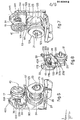
- a splicer device 10 has a carrying frame 11, which in this example is substantially U-shaped and consists of a base 111 and two side plates 211 and 311 in which various components are fitted and positioned.
- the device 10 On its front and rear in Figs.1 and 2 the device 10 has shields 12 and 112 respectively.
- the shields 12-112 comprise positioner notches 212, which are suitably shaped and serve to enable two yarns which are to be spliced 77-78 to be inserted and positioned in the device 10.
- Positioner rods 312 are included in cooperation with the positioner notches 212.
- rods 312 are solidly fixed to plate means 13 (Fig.3) marked with lines of dashes in Figs.1 and 2 so as to allow means 15-115 which balance twists to be seen.
- the device 10 comprises means 14 to discharge yarn, which in this example include two arms, 114 and 214 respectively, with shaped ends; in this case the arms 114-214 can be actuated by a machine (not shown here) to which the device 10 is fitted, but could also be actuated by the device 10 itself.
- one or both of the arms 114-214 can also perform the function of inserting the yarn, perhaps in cooperation with auxiliary yarn-insertion means located on the machine to which the device 10 is fitted.
- actuation takes place by means of a rod 16 comprising teeth.
- This rod 16 is actuated at its lower end at 116 (Fig.3), as said above, by the machine to which the device 10 is fitted, and engages with its upper portion a toothed segment of a shaft 216 which bears the arms 114-214 at its ends.
- a torsion spring 316 in this example returns the shaft 216 and therewith the arms 114-214 to the position shown for discharge of the yarn.
- the yarns 77-78 are inserted in the device 10 through the positioner notches 212, so that the yarns 77-78 become positioned between plate means 17 and 18, - which are opened at the beginning of the splicing procedure.
- the yarns 77-78 are positioned substantially parallel (see also Figs.14 to 19).
- the means 15-115 to balance twists are also shown in Figs.l and 2.
- these means 15-115 comprise a pressure jaw 56-156 and a yielding jaw 57-157, both jaws being pivoted at 58.
- the yielding jaw 57-157 is returned by spring means 59 and includes a small block 60 which can rotate through a certain angle on or in its support seating in both directions for an excellent engagement of the yarn, the block 60 being able to adapt itself to the working profile of the pressure jaw 56-156.
- the pressure jaw 56-156 is actuated by a connecting rod 61-161, which is connected rotatably to an adjustment plate 62, the position of which can be adjusted in relation to a lever 90 by screw means 162 and can be read by means of nicks 262 or equivalent means (Figs.1 and la).
- Such plate 62 is moved, by means of a pin 362, by a lug 246 of a lever 46, which is actuated by a track 27 on a drum 21 (Fig.6), such track 27 acting on a lug 146.
- the lever 46 is installed so as to idle on a shaft 89.
- Motion is transmitted by the plate 62 to the lever 90, to which the plate 62 is solidly fixed momentarily.
- the lever 90 in its turn rotates the shaft 89 and therewith a lever 190 relative to the other means 115 that balances twists.
- the levers 90-190 are solidly fixed to the opposite ends of the shaft 89.
- one single adjustment plate 62 serves both the means 15-115 that balance twists and thus facilitates the adjustment and timing, which in this way are performed at one single point; thus the actuation, setting, adjustment and timing of the means 15-115 are simplified.
- lever 46 is also called a "release lever” since it cooperates with projections 149 to release grippers 42-142 (see Figs.11-12).
- the track 27 acts on the lug 146 of the lever 46 and causes rotation of the levers 90-190 and therefore actuation of the jaws 56-156 by means of the arms or connecting rods 61-161.
- the tail end 177-178 (see Fig.18) of the engaged yarn 77-78 is now put under tension, such tension being made axial by an abutment formed by the edge of the positioner notch 212, and undergoes also an action which can also be a pre-plucking action and which facilitates the next operation of the plucking and/or tearing means 42-142.
- the tensioning of the tail ends 177-178 by the means 15-115 that balance twists has the purpose of enabling the twists in the zone between untwisting and retwisting rings 63-64 and inner clamp means 73 to be balanced with the twists in the zone located outside the rings 63-64 and stretching up to the point of engagement of the yarn between the jaw 56-156 and the block 60.
- twist-balancing means 15-115 has the result that it is possible to determine as required the moment at which, during or at the end of untwisting, a segment of yarn with controlied twists is created in the segment of tail end of yarn outside the rings 63-64.
- the actuation of the twist-balancing means 15-115 may provide a slight further travel, which has the function of tensioning the yarn. This facilitates compensation between the opposite twists contained in the segments of yarn in question.
- Motion to actuate the device 10 enters in a known manner with the required characteristics by means of a motion-input wheel 19 having an axis of rotation 20.
- Such motion-input wheel 19 transmits rotation to the drum-type cam or drum 21 and to a cam 22 which actuates fins 52-53, such cam 22 being coaxial with the drum-type cam 21 (see Figs.11-13).
- Such drum-type cam 21 comprises in this example six paths or tracks, which can be seen in particular in Figs.6 and 7.
- a track 23 on the front of the drum 21 controls the rotation of one 18 of the plate means 17-18.
- Another track 123 which in this example is identical to the track 23 but which can have another conformation, is machined on the opposite face of the drum 21 (see Fig.7).
- Such track 123 acts on a lug 128 of a lever 28 which rotates the plate means 17-18 and which is'oscillated on an axis 29 (Fig.9).
- the lever 28 that rotates the plate means 17 comprises a toothed sector 228 that meshes with a motion-inversion gear wheel 32, which in turn transmits motion to a gear wheel 33 of the plate means 17.
- Rotation of the outer plate 18 is obtained by means of an analogous lever 30 (Fig.10) pivoted at 31.
- a lug 130 on such lever 30 is engaged in the track 23 (see Fig.6).
- the lever 30 with a toothed sector 230 actuates a gear wheel 34 of the plate 18 directly.
- a track 24 (see Figs.6 and 7) serves to move the plate means 17 forward towards the plate means 18 and, in this example, to govern part of the reciprocal interactions between the plate means 17-18.
- Such track 24 contains a cutaway portion 124 in correspondence with which the actuation of the plate 17 is controlled by a separate adjustable cam 37 (see Fig.9).
- a track 25 contains a cutaway portion 125 corresponding to actuation by a separate cam 38 (see Figs.7 and 10).
- cam 38 controls the start of the retreat of the plate 18 at the end of retwisting.
- cams 37-38 By adjusting such cams 37-38 separately it is possible to determine separately the angle of rotation to which the start of untwisting corresponds, and also the angle of counterrotation to which the end of retwisting corresponds, so as to obtain the best splicing results in each individual case.
- the track 24 on the cam 21 acts on a lug 139 on a U-shaped lever 39 which can rotate about an axis 239.
- Such lever 39 acts with its lug 339 on a lug-lodgement recess 133 comprised in cooperation with the gear wheel 33 solidly fixed to the plate means 17.
- the lug 339 comprises an eccentric means 439 with a locknut to pre-set the forward movement of the plate 17.
- the track 25 acts on a lug 141 of a U-shaped lever 41 having an axis 241 (see Fig.7).
- the lever 41 governs the forward movement of the plate 18 by means of a lug 341 cooperating with a lug-lodgement recess 134 analogous to the recess 133.
- the lug 341 too comprises an adjustment means 441 wholly analogous to the adjustable eccentric 439 of the U-shaped lever 39.
- the lever 41 is kept pressed against the track 25 by a spring means 87 (see Fig.6) which rests at its opposite ends against the lever 41 and lever 39 respectively.
- the cams 37-38 are solidly fixed to adjustable sectors 35-36 having analogous natures and located on the side plates 311 and 211 respectively and capable of being clamped by screw means at the required angle.
- Such angle can be read with indicators such as reference notches or the like (Figs.1-2-3).
- Figs.4 and 5 and, in greater detail; Figs.11 and 12 show the plucking and/or tearing means 42-142, which will also be called the grippers 42-142 hereinafter for the sake of brevity.
- such grippers 42-142 are actuated by means of a U-shaped lever 43, of which a lug 143 is engaged in a track 26 on the drum 21.
- Such U-shaped lever 43 comprises, in correspondence with each gripper 42-142, an actuation pin or projection 243, which engages a lever means 44; the grippers 42-142 are fitted so as to idle on a shaft 45.
- the release of the grippers 42-142 is governed by the release lever 46, which actuates in a coordinated manner also the movement of the twist-balancing means 15-115, as described earlier (see Fig.1a).
- the structure of the grippers 42-142 makes it possible to obtain an action of engagement of the yarn 77-78 such that the yarns always remain in a direction along a diameter of the plates 17-18.
- the structure of the grippers 42-142 is shown in particular in Figs.11-12. In these figures it is possible to see that the grippers 42-142 have a stationary portion 48-148 and a movable portion 47-147.
- the stationary portion 48-148 abuts against an abutment 93-193 comprised on the actuation lever 41 (see Fig.10), and a further displacement of the pin 243 causes rotation of the lever 44 about its fulcrum 144.
- the lever 44 is engaged in this way by a hook means 49 with a spring 249.
- the movable portion 47-147 is guided at 50 by a pin/slot coupling.
- the resilient yielding of the ring 151 determines the clamping force exerted on the tail end 177-178.
- Axial plucking of the tail ends of yarn is actuated by the fin-actuation cam 22, which is coaxial with the drum 21 and acts on a lever 153 of the fin 53 (Fig.13). Such lever 153 in its turn acts on a lever 152 of the fin 52.
- the fins 52-53 are rotatably anchored to the side plates 211-311 respectively at 54-154.
- the fin 52 comprises a projection 252 connected to return spring means 55.
- the steps in the movement of the grippers 42-142 therefore, include at least:
- the opening of the grippers 42-142 is performed by an active movement of the lever 46 driven by the track 27.
- Such movements can be conditioned and coordinated as required according to the conformation and timing applied to the track 26 and to the fin-actuation cam 22.
- Figs. 14 to 19 show in particular the plate means 17-18, which can be the same as each other or be differently specialised and/or dimensioned.
- the dimensions of the plate means 17-18 and their characteristics and special features can also be varied to suit variations in the type of yarn and/or in the average length of the fibres.
- both of the plate means 17-18 comprise advantageously an untwist-retwist ring means 63 and 64 respectively and a retwist disk means or disk 65 and 66 respectively.
- the ring 64 is made in cooperation with and is solidly fixed to the disk 66.
- the ring means 63-64 and disks 65-66 are provided with means which prevent them from rotating and being unintentionally separated from containment casings 67-68; the latter means are known and we shall I not dwell I upon them.
- the disk 65, ring 63 and the ring 64/disk 66 assemblage are kept in position by spring means 69, which here are compression springs.
- the position of rest of the disks 65-66 and rings 63-64 is determined by the heads of screws 83-84.
- the retwist means or disks 65-66 can be flat, as in fig.14, or can be equipped with specialized operational means 70 to suit the specific requirements, as in Fig.16.
- the operational means 70 are conformed advantageously in stripes with a development opposite in one half f of the retwist means 66 to that of the other half, the stripes being formed in spirals.
- Such stripes are advantageously such as to contain spaces between one operational means 70 and its neighbour, so as to provide a lengthwise drawing action on the fibres and hairs on the outside of the yarn.
- the operational means 70 can lie substantially on one plane but can lie also on an undulating or curved surface so as to obtain special effects.
- the surfaces 70 of one disk and/or ring can be conjugate with the corresponding and/or facing surfaces of the opposite disk and/or ring. In a variant they can also be differentiated.
- the retwist means 65 and/or 66 comprise means 71-72 to couple the yarns and also inner means 73 to clamp the yarns 77-78.
- the means 71-72 to couple the yarns are provided in a desired position inside the inner periphery of the rings 63-64, such position perhaps being adjustable.
- the means 71-72 to couple the yarns consist, in this example, of pairs of pins, and we shall I use that name in the following text for the sake of brevity.
- the inner clamp means 73 in this case consist of an end surface of a projection 173 (see Fig.15), and such surface 73 clamps the yarns 77-78 against the retwist means 66 in the central zone of the latter 66.
- Such retwist means 66 includes in this instance an insert 172 which coincides with the area where the yarns are clamped, and faces and is opposite to the surface 73.
- inner clamp means 73 in required radial positions, which possibly may be adjustable.
- Clamp means 73 can also be provided which can be adjusted separately for each yarn 77-78.
- the pins 72 are solidly fixed to the disk 66 and can move with the same in an axial direction as well.
- the pins 71 likewise are solidly fixed to the disk 65.
- pins 71-72 lie on different circumferences but could also lie on the same or neighbouring circumferences.
- the projection 173 is immovably fixed to a plate 74 solidly secured to the casing 67, and therefore a relative axial displacement takes place between the projection 173 and the disk 65 when the reciprocal axial positions of the casing'67 and disk 65 are varied.
- the plate 17 comprises also means 75 to cause approach of small remaining tails of yarn, such means consisting here of combs; such means 75 will be called combs hereinafter.
- Such combs 75 are normally closed (position 75A of Fig.14) at a position below the plane on which the working surfaces lie, and are opened by the action of a prong 176 of a finned lever 76 on a lever 175 that opens the combs 75, before the excessive tail ends of yarn 177-178 are plucked and/or torn.
- the prong 176 engages the lever 175 that opens the combs 75, and thus causes the combs 75 to open.
- Such closure is governed by the gripper 142, which in its movement about its axis 45, towards the end of its travel, engages a protrusion 276 of the finned lever 76.
- the finned lever 76 is then rotated outwards, overcoming the resistance of spring means 376.
- the lever 175 that opens the combs 75 is thus released and causes the closure of the combs 75 by spring means 275 (see Fig.14).
- Fig.14 shows in particular the combs 75 arranged so as to counterrotate on their axis 79 and normally kept in their closed position 75A by the spring means 275. tn Fig.14 the combs 75 are shown open for greater clarity.
- a lever 80 to couple the combs 75 with its pivot at 180 comprises two pins 280 on opposite sides of the pivot 180. Such pins 280 are engaged in corresponding recesses in the combs 75.
- spacer means 91 are comprised which have the purpose of pre-setting a free gap between the opposed surfaces of the plates 17-18, as we said earlier in another part of this description.
- such means 91 include slide blocks 191 cooperating with the disk 65 and also with the ring means 63.
- the height of the slide blocks 191, which can be replaced and/or adjusted, and the depth of the slide paths 219 are chosen so as to leave a pre-set gap between the working surfaces of the disks 65-66 and of the rings 63-64 respectively.
- the width of such gap is determined in such a way that the surfaces can press against yarns 77-78 placed between them but never come into contact with each other, thus obviating occurrence of wear and considerable friction and also, as said earlier, avoiding an excessive undesired pressure on the yarn.
- Fig.15 shows the step of insertion of yarns 77-78;
- Fig.17 shows the untwisting action;
- Fig.18 shows the action of clamping the yarns 77-78;
- Fig.19 shows the start of the retwisting action.
- Rotatio6 of the wheel 19 sets in rotation the drum 21, which acts on the various means in relation to the procedure.
- the pins 71-72 have brought the untwisted yarns 77-78 together in the meantime, thus enabling the central zone of the yarns 77-78, which are substantially parallel and in contact with each other, to be controlled.
- the pins 71-72 are lodged in circumferential hollows 82-81 respectively made in the disks 66-65 respectively.
- the projection 173, and also an insert 172 in this case, are shaped so as not to interrupt the continuity of such hollows 81-82.
- the combs 75 which are already in a circumferential position corresponding to the yarns 77-78 at the end of untwisting, are opened by the action of the finned lever 76 on the lever 175 that opens the combs 75.
- Such combs 75 are caused to protrude through circumferential slots 85 in the disk 65 and ring 63 when the plates 17-18 are thrust against each other, as shown in Fig.18.
- the yarns 77-78 are clamped in this way between the surfaces 73-172 in their central .segment coinciding with the clamp means 73 but are not constrained by the surfaces of the disks 65-66 or rings 63-64.
- twist-balancing means 15-115 in the meanwhile have engaged the excessive tail ends 177-178, as shown diagrammatically in Fig.18.
- Such means 15-115 carry out tensioning of the yarns 77-78 to the required degree, enabling the twists to be cancelled in the segments of yarn involved, as we said earlier.
- the gripper means 42-142 engage the yarns 77-78.
- the casings 67-68 are in circumferential contact with each other, but the cutaway portions 167-168 respectively (see Figs.6-7) permit the tail ends 177-178 to be plucked and/or torn and leave a passage free for such tail ends.
- means 86 that clamp twists constrain the portions of the yarns 77-78 which are not to be torn, against the outer edge of-the ring 63 (Fig. 18) and prevent the negative twists comprised in the segment of the yarns 77-78 contained between the outer periphery of the ring means 63-64 and the inner clamp means 73 from becoming lost by spreading along the yarns 77-78 through the cutaway portions 167-168 and outwards beyond the ring means 63-64, and from being cancelled owing to the presence of the positive twists existing outside the rings 63-64.
- the clamping produced by the inner clamp means 73 has the effect that the small remaining ta.ils 277-278 of yarn are tapered from a position of greatest thickness in the neighbourhood of the clamp means 73 to an end position of smallest thickness in the neighbourhood of the outer periphery of the rings 63-64.
- the grippers 42-142 perform the plucking and/or tearing action with a combination of movements conditioned by the track 26 and cam 22 after the twist-balancing means 15-115 have been opened.
- the gripper 142 presses against the protrusion 276 of the finned lever 76 and thus causes release of the lever 175 by the finned lever 76 itself, with a resultant closure of the combs 75.
- the combs 75 then bring the remaining small tails 277-278 near the yarns 78-77 respectively.
- the grippers 42-142 are opened by the action of the release lever 46 on the projections 149.
- the plucked tai) I ends 177-178 are discharged by known means when the grippers 42-142 are opened.
- the combs 75 move backwards with the retreat of the casing 67, to which they are solidly fixed axially, below the surface of the disk 65, thus freeing the remaining tails 277-278 and yarns 78-77, which have now been positioned adjacent to each other.
- the yarns 77-78 are therefore now controlled along the whole extent of the disks 65-66 and rings 63-64.
- Fig.19 shows the start of the retwisting step, with the means 73 no longer clamping the yarns 77-78 and with the disks 65-66 and rings 63-64 pressing against the yarns 77-78.
- both the ring means 63-64 and the respective retwist disk means 65-66 cooperate in obtaining the required degree of retwisting.
- the pins 71-72 move away from each other, running within their respective hollows 82-81 and ensuring lack of contact with the coupled yarns.
- the plates 17-18 move apart from each other, such movement being conditioned by the adjustable cam 38, which acts on the plate 18.
- the means 14 which discharge yarn expel the spliced yarn from the device 10.
- Figs.20 and 21 show a possible embodiment of means 101 to tension yarns.
- a rocker arm 98 is drawn by the lug 246 of the lever 46 by means of a movable pin or pivot 198 (see Fig.1a).
- This arm 98 which can rotate about such pivot 198, actuates a crank 97 by means of an actuation lug 298.
- An inclined slot 197 in the crank 97 cooperates with the lug 298.
- An adjustable cam 9.6 conditions the radial position of the lug 298 in relation to an axis 89 of rotation.
- Such travel determines the value of the traction which the yarns 77-78 undergo after being engaged between the jaw 94 and a block 160 on a yielding jaw 95.
- An abutment 195 establishes the initial position of such jaw 95.
- Fig.20 shows how the end of the movable yielding jaw 95 and the block 160 have a width such as to enable both the yarns 77-78, which are positioned by means of the positioner notch 212 and positioner rod 312, to be engaged.
- Fig.21 shows a variant suitable for performing tensioning of the tail I ends to be plucked and/or torn in two stages, whereas the segments of yarn to be left integral are tensioned once only.
- two movable jaws one to "tension yarn” 194 and one to “tension a tail end” 294, are provided. Both these jaws 194-294 are pivoted at 58.
- the method of working is as follows.
- the crank 97 initially actuates the jaw 194 by means of the connecting rod 261.
- the jaw 194 pulls the jaw 294 by means of an entraining pin 494.
- the overall travel of the jaws 194-294 is determined by the adjustment imparted to the cam 96, such adjustment taking place in the same way as in Fig.20.
- the jaws 194-294 engage the tail I end 177 and the yarn 78 against the block 160.
- the track 27 on the drum 21, being suitably conformed for this specific case, causes the return of the crank 97 and thus of the jaw 194.
- the jaw 294 remains in its closure position with the tail I end 177 engaged against the block 160, this jaw 294 being held by the hook 99.
- This hook 100 can then engage the jaw 294 in correspondence with a recess 394.
- jaws 194-294 only the jaw 294 can take the tail end 177 for further tensioning, whereas the jaw 194, being further to the rear, can no longer engage the yarn 78 that is to be left integral.
- This second forward travel takes place after the opening of the rings 63-64 and disks 65-66, with the yarns 77-78 clamped by the inner clamp means 73.
- the jaw 294 and hook 100 are now re-positioned reciprocally and take up their reciprocal I positions of Fig. 21.
- Both the jaws 194-294 take up once more their initial positions owing to the act ion of the crank 97 and connecting rod 261.
- the variant of Fig.21 enables the device to be used also with a method of working analogous to that of the variant of Fig.20. For this purpose it is enough to clamp the hook 99 in its initial position 99A with known means.
- the hook 100 cannot trip since the jaws 194-294 do not take up the staggered positions caused by the clamping of the jaw 294 by the hook 99.
- jaws 194-294 act in a manner wholly analogous to the jaw 94 of Fig.20.
Landscapes
- Spinning Or Twisting Of Yarns (AREA)
- Auxiliary Weaving Apparatuses, Weavers' Tools, And Shuttles (AREA)
Applications Claiming Priority (2)
| Application Number | Priority Date | Filing Date | Title |
|---|---|---|---|
| IT8346983 | 1983-10-04 | ||
| IT83469/83A IT1175131B (it) | 1983-10-04 | 1983-10-04 | Perfezionamenti ai giuntafili per la giunzione meccanica di fili tessili e giuntafili meccanico adottante tali perfezionamenti |
Publications (2)
| Publication Number | Publication Date |
|---|---|
| EP0140412A1 true EP0140412A1 (de) | 1985-05-08 |
| EP0140412B1 EP0140412B1 (de) | 1987-11-19 |
Family
ID=11322327
Family Applications (1)
| Application Number | Title | Priority Date | Filing Date |
|---|---|---|---|
| EP84201306A Expired EP0140412B1 (de) | 1983-10-04 | 1984-09-11 | Spleissvorrichtungen für das mechanische Spleissen von Textilgarnen, und mechanische Spleissvorrichtung, die derartige Vorrichtungen benutzt |
Country Status (5)
| Country | Link |
|---|---|
| US (1) | US4637205A (de) |
| EP (1) | EP0140412B1 (de) |
| JP (1) | JP2518812B2 (de) |
| DE (2) | DE140412T1 (de) |
| IT (1) | IT1175131B (de) |
Cited By (10)
| Publication number | Priority date | Publication date | Assignee | Title |
|---|---|---|---|---|
| WO2007048466A1 (de) * | 2005-10-29 | 2007-05-03 | Oerlikon Textile Gmbh & Co. Kg | Fadenverbindungsvorrichtung |
| CN112093584A (zh) * | 2019-06-18 | 2020-12-18 | 卓郎纺织解决方案两合股份有限公司 | 用于无结连接两个纱线头的纱线连接装置 |
| CN112093586A (zh) * | 2019-06-18 | 2020-12-18 | 卓郎纺织解决方案两合股份有限公司 | 用于无结连接两个纱线头的纱线连接装置 |
| DE102019116483A1 (de) * | 2019-06-18 | 2020-12-24 | Saurer Spinning Solutions Gmbh & Co. Kg | Reibscheiben für eine Fadenverbindungsvorrichtung |
| DE102019116484A1 (de) * | 2019-06-18 | 2020-12-24 | Saurer Spinning Solutions Gmbh & Co. Kg | Fadenverbindungsvorrichtung zum knotenfreien Verbinden zweier Fadenenden |
| DE102019116485A1 (de) * | 2019-06-18 | 2020-12-24 | Saurer Spinning Solutions Gmbh & Co. Kg | Reibscheiben für eine Fadenverbindungsvorrichtung |
| DE102019116479A1 (de) * | 2019-06-18 | 2020-12-24 | Saurer Spinning Solutions Gmbh & Co. Kg | Reibscheiben für eine Fadenverbindungsvorrichtung |
| DE102019116488A1 (de) * | 2019-06-18 | 2020-12-24 | Saurer Spinning Solutions Gmbh & Co. Kg | Fadenverbindungsvorrichtung zum knotenfreien Verbinden zweier Fadenenden |
| DE102019116481A1 (de) * | 2019-06-18 | 2020-12-24 | Saurer Spinning Solutions Gmbh & Co. Kg | Reibscheiben für eine Fadenverbindungsvorrichtung |
| DE102019116482A1 (de) * | 2019-06-18 | 2020-12-24 | Saurer Spinning Solutions Gmbh & Co. Kg | Fadenverbindungsvorrichtung zum knotenfreien Verbinden zweier Fadenenden |
Families Citing this family (10)
| Publication number | Priority date | Publication date | Assignee | Title |
|---|---|---|---|---|
| ES8705935A1 (es) * | 1986-06-11 | 1987-05-16 | Pujol Isern Carlos | Procedimiento y dispositivo para empalmar dos hilos textiles |
| ES2021390B3 (es) * | 1986-06-11 | 1991-11-01 | Carlos Pujol-Isern | Procedimiento y dispositivo para anudar dos hilos textiles. |
| CH670661A5 (de) * | 1987-02-20 | 1989-06-30 | Mesdan Spa | |
| DE4426753A1 (de) | 1994-07-28 | 1996-02-01 | Bayer Ag | Mittel zur Bekämpfung von Pflanzenschädlingen |
| DE102004051038A1 (de) * | 2004-10-20 | 2006-04-27 | Saurer Gmbh & Co. Kg | Fadenspleißvorrichtung |
| DE102006000824A1 (de) * | 2006-01-05 | 2007-07-12 | Saurer Gmbh & Co. Kg | Fadenspleißvorrichtung für eine Kreuzspulen herstellende Textilmaschine |
| IT201900021060A1 (it) * | 2019-11-13 | 2021-05-13 | Hayabusa S R L | Perfezionamenti ad un dispositivo di giunzione di fili tessili e relativo dispositivo |
| IT201900021258A1 (it) * | 2019-11-15 | 2021-05-15 | Hayabusa S R L | Dispositivo di giunzione di fili tessili e relativo metodo di giunzione |
| IT202100020276A1 (it) | 2021-07-29 | 2023-01-29 | Hayabusa S R L | Dispositivo di giunzione di fili tessili e relativo metodo di giunzione |
| EP4328162A1 (de) | 2022-08-26 | 2024-02-28 | Savio Macchine Tessili S.p.A. | Fadenspleissvorrichtung mit verbesserten endreissmitteln und zugehöriges betriebsverfahren |
Citations (3)
| Publication number | Priority date | Publication date | Assignee | Title |
|---|---|---|---|---|
| EP0039609A1 (de) * | 1980-05-05 | 1981-11-11 | Officine Savio S.p.A. | Verfahren und Vorrichtung zum Verbinden von zwei gesponnenen Fasergarnen |
| GB2083090A (en) * | 1980-08-02 | 1982-03-17 | Reiners Verwaltungs Gmbh | Apparatus for connecting textile threads by splicing by means of compressed air |
| EP0078778A2 (de) * | 1981-11-04 | 1983-05-11 | Officine Savio S.p.A. | Verfahren und Vorrichtung zum mechanischen Verbinden von textilem Garn |
Family Cites Families (10)
| Publication number | Priority date | Publication date | Assignee | Title |
|---|---|---|---|---|
| US2028144A (en) * | 1931-04-23 | 1936-01-21 | John F Cavanagh | Thread splicing device |
| GB548423A (en) * | 1941-04-07 | 1942-10-09 | Cook & Co Manchester Ltd | Improvements in and relating to apparatus for joining pieces of yarn |
| US3307339A (en) * | 1966-06-27 | 1967-03-07 | Clarence H Porter | Apparatus for joining threads |
| US3633352A (en) * | 1969-12-19 | 1972-01-11 | Thomas E Marriner | Splicer for nonwoven fibers |
| CH623290A5 (de) * | 1978-06-12 | 1981-05-29 | Fomento Inversiones Ind | |
| CH646209A5 (de) * | 1980-07-23 | 1984-11-15 | Zellweger Uster Ag | Verfahren und vorrichtung zur erzeugung einer verbindung von faserverbaenden. |
| CH646210A5 (de) * | 1980-07-23 | 1984-11-15 | Zellweger Uster Ag | Verfahren und vorrichtung zur erzeugung einer verbindung von faserverbaenden. |
| CH646208A5 (de) * | 1980-07-23 | 1984-11-15 | Zellweger Uster Ag | Verfahren und vorrichtung zur verminderung abrupten querschnittverlaufs bei der verbindung von faserverbaenden. |
| JPS6013941B2 (ja) * | 1980-12-13 | 1985-04-10 | 村田機械株式会社 | 糸捲機における異常糸継防止方法 |
| IT1168553B (it) * | 1981-11-04 | 1987-05-20 | Savio Spa | Dispositivo di pinzatura e strappo per splicer |
-
1983
- 1983-10-04 IT IT83469/83A patent/IT1175131B/it active
-
1984
- 1984-09-11 DE DE198484201306T patent/DE140412T1/de active Pending
- 1984-09-11 EP EP84201306A patent/EP0140412B1/de not_active Expired
- 1984-09-11 DE DE8484201306T patent/DE3467558D1/de not_active Expired
- 1984-09-17 US US06/651,333 patent/US4637205A/en not_active Expired - Fee Related
- 1984-10-04 JP JP59209018A patent/JP2518812B2/ja not_active Expired - Lifetime
Patent Citations (3)
| Publication number | Priority date | Publication date | Assignee | Title |
|---|---|---|---|---|
| EP0039609A1 (de) * | 1980-05-05 | 1981-11-11 | Officine Savio S.p.A. | Verfahren und Vorrichtung zum Verbinden von zwei gesponnenen Fasergarnen |
| GB2083090A (en) * | 1980-08-02 | 1982-03-17 | Reiners Verwaltungs Gmbh | Apparatus for connecting textile threads by splicing by means of compressed air |
| EP0078778A2 (de) * | 1981-11-04 | 1983-05-11 | Officine Savio S.p.A. | Verfahren und Vorrichtung zum mechanischen Verbinden von textilem Garn |
Cited By (12)
| Publication number | Priority date | Publication date | Assignee | Title |
|---|---|---|---|---|
| WO2007048466A1 (de) * | 2005-10-29 | 2007-05-03 | Oerlikon Textile Gmbh & Co. Kg | Fadenverbindungsvorrichtung |
| CN101291863B (zh) * | 2005-10-29 | 2012-04-25 | 欧瑞康纺织有限及两合公司 | 纱线连结装置 |
| CN112093584A (zh) * | 2019-06-18 | 2020-12-18 | 卓郎纺织解决方案两合股份有限公司 | 用于无结连接两个纱线头的纱线连接装置 |
| CN112093586A (zh) * | 2019-06-18 | 2020-12-18 | 卓郎纺织解决方案两合股份有限公司 | 用于无结连接两个纱线头的纱线连接装置 |
| DE102019116483A1 (de) * | 2019-06-18 | 2020-12-24 | Saurer Spinning Solutions Gmbh & Co. Kg | Reibscheiben für eine Fadenverbindungsvorrichtung |
| DE102019116484A1 (de) * | 2019-06-18 | 2020-12-24 | Saurer Spinning Solutions Gmbh & Co. Kg | Fadenverbindungsvorrichtung zum knotenfreien Verbinden zweier Fadenenden |
| DE102019116485A1 (de) * | 2019-06-18 | 2020-12-24 | Saurer Spinning Solutions Gmbh & Co. Kg | Reibscheiben für eine Fadenverbindungsvorrichtung |
| DE102019116479A1 (de) * | 2019-06-18 | 2020-12-24 | Saurer Spinning Solutions Gmbh & Co. Kg | Reibscheiben für eine Fadenverbindungsvorrichtung |
| DE102019116488A1 (de) * | 2019-06-18 | 2020-12-24 | Saurer Spinning Solutions Gmbh & Co. Kg | Fadenverbindungsvorrichtung zum knotenfreien Verbinden zweier Fadenenden |
| DE102019116481A1 (de) * | 2019-06-18 | 2020-12-24 | Saurer Spinning Solutions Gmbh & Co. Kg | Reibscheiben für eine Fadenverbindungsvorrichtung |
| DE102019116486A1 (de) * | 2019-06-18 | 2020-12-24 | Saurer Spinning Solutions Gmbh & Co. Kg | Fadenverbindungsvorrichtung zum knotenfreien Verbinden zweier Fadenenden |
| DE102019116482A1 (de) * | 2019-06-18 | 2020-12-24 | Saurer Spinning Solutions Gmbh & Co. Kg | Fadenverbindungsvorrichtung zum knotenfreien Verbinden zweier Fadenenden |
Also Published As
| Publication number | Publication date |
|---|---|
| EP0140412B1 (de) | 1987-11-19 |
| US4637205A (en) | 1987-01-20 |
| DE140412T1 (de) | 1985-09-26 |
| IT8383469A0 (it) | 1983-10-04 |
| JPS60122669A (ja) | 1985-07-01 |
| IT1175131B (it) | 1987-07-01 |
| JP2518812B2 (ja) | 1996-07-31 |
| DE3467558D1 (en) | 1987-12-23 |
Similar Documents
| Publication | Publication Date | Title |
|---|---|---|
| US4637205A (en) | Splicer device for the mechanical splicing of textile yarns | |
| US4641688A (en) | Weft thread braking mechanism having a stepwise controllable braking effect | |
| EP0078778B1 (de) | Verfahren und Vorrichtung zum mechanischen Verbinden von textilem Garn | |
| US3428096A (en) | Machine for tying coils and packs of iron for instance of rolled iron with wire | |
| US4583356A (en) | Splicer device to disassemble and recompose yarn mechanically | |
| EP0120523B1 (de) | Spleissvorrichtung zur mechanischen Spleissverbindung von Textilfäden | |
| US4494367A (en) | Splicer device to disassemble and recompose yarn mechanically | |
| US2730142A (en) | Apparatus for binding piles of sheets | |
| US3347282A (en) | Weft thread-cutting mechanism for shuttleless looms | |
| KR100248532B1 (ko) | 그립퍼 및 투사 직기용 위사 공급기 | |
| US3974551A (en) | Thread clamp for warp end tying-in machines | |
| NO168457B (no) | Middel til vasking og skylling av haar. | |
| DE440743C (de) | Antriebsvorrichtung der Zange von Flachkaemmaschinen | |
| JPH0446874B2 (de) | ||
| JPH0410440B2 (de) | ||
| SU1123063A1 (ru) | Устройство дл скрутки электрических проводов | |
| DE453115C (de) | Flachkaemmaschine mit umlaufender Trommel | |
| SU575386A1 (ru) | Крутильно-мотальный механизм пр дильно-крутильной машины | |
| JP2643992B2 (ja) | コイルばねの供給方法 | |
| EP0043393A1 (de) | Drahtknotmaschine | |
| US1639146A (en) | Wrapping wire | |
| US1572181A (en) | Knotter device | |
| US1605650A (en) | Roll-holder for wrapping machines | |
| US1273299A (en) | Heilmann-type comber. | |
| JPH0428617B2 (de) |
Legal Events
| Date | Code | Title | Description |
|---|---|---|---|
| PUAI | Public reference made under article 153(3) epc to a published international application that has entered the european phase |
Free format text: ORIGINAL CODE: 0009012 |
|
| AK | Designated contracting states |
Designated state(s): CH DE FR GB LI |
|
| EL | Fr: translation of claims filed | ||
| DET | De: translation of patent claims | ||
| 17P | Request for examination filed |
Effective date: 19851015 |
|
| 17Q | First examination report despatched |
Effective date: 19860515 |
|
| GRAA | (expected) grant |
Free format text: ORIGINAL CODE: 0009210 |
|
| AK | Designated contracting states |
Kind code of ref document: B1 Designated state(s): CH DE FR GB LI |
|
| REF | Corresponds to: |
Ref document number: 3467558 Country of ref document: DE Date of ref document: 19871223 |
|
| ET | Fr: translation filed | ||
| PLBE | No opposition filed within time limit |
Free format text: ORIGINAL CODE: 0009261 |
|
| STAA | Information on the status of an ep patent application or granted ep patent |
Free format text: STATUS: NO OPPOSITION FILED WITHIN TIME LIMIT |
|
| 26N | No opposition filed | ||
| REG | Reference to a national code |
Ref country code: CH Ref legal event code: PUE Owner name: SAVIO S.P.A. |
|
| REG | Reference to a national code |
Ref country code: FR Ref legal event code: CD |
|
| REG | Reference to a national code |
Ref country code: GB Ref legal event code: 732 |
|
| PGFP | Annual fee paid to national office [announced via postgrant information from national office to epo] |
Ref country code: FR Payment date: 19950818 Year of fee payment: 12 |
|
| PGFP | Annual fee paid to national office [announced via postgrant information from national office to epo] |
Ref country code: GB Payment date: 19950908 Year of fee payment: 12 |
|
| PGFP | Annual fee paid to national office [announced via postgrant information from national office to epo] |
Ref country code: DE Payment date: 19950912 Year of fee payment: 12 |
|
| PGFP | Annual fee paid to national office [announced via postgrant information from national office to epo] |
Ref country code: CH Payment date: 19951012 Year of fee payment: 12 |
|
| PG25 | Lapsed in a contracting state [announced via postgrant information from national office to epo] |
Ref country code: GB Effective date: 19960911 |
|
| PG25 | Lapsed in a contracting state [announced via postgrant information from national office to epo] |
Ref country code: LI Effective date: 19960930 Ref country code: FR Effective date: 19960930 Ref country code: CH Effective date: 19960930 |
|
| GBPC | Gb: european patent ceased through non-payment of renewal fee |
Effective date: 19960911 |
|
| REG | Reference to a national code |
Ref country code: CH Ref legal event code: PL |
|
| PG25 | Lapsed in a contracting state [announced via postgrant information from national office to epo] |
Ref country code: DE Effective date: 19970603 |
|
| REG | Reference to a national code |
Ref country code: FR Ref legal event code: ST |
|
| REG | Reference to a national code |
Ref country code: FR Ref legal event code: ST |