EP0139085A1 - Procédé et brûleur pour la combustion des combustibles liquides ou gazeux avec diminution de la formation de NOx - Google Patents
Procédé et brûleur pour la combustion des combustibles liquides ou gazeux avec diminution de la formation de NOx Download PDFInfo
- Publication number
- EP0139085A1 EP0139085A1 EP84106790A EP84106790A EP0139085A1 EP 0139085 A1 EP0139085 A1 EP 0139085A1 EP 84106790 A EP84106790 A EP 84106790A EP 84106790 A EP84106790 A EP 84106790A EP 0139085 A1 EP0139085 A1 EP 0139085A1
- Authority
- EP
- European Patent Office
- Prior art keywords
- air
- guide tube
- burner
- combustion
- air box
- Prior art date
- Legal status (The legal status is an assumption and is not a legal conclusion. Google has not performed a legal analysis and makes no representation as to the accuracy of the status listed.)
- Granted
Links
Images

Classifications
-
- F—MECHANICAL ENGINEERING; LIGHTING; HEATING; WEAPONS; BLASTING
- F23—COMBUSTION APPARATUS; COMBUSTION PROCESSES
- F23C—METHODS OR APPARATUS FOR COMBUSTION USING FLUID FUEL OR SOLID FUEL SUSPENDED IN A CARRIER GAS OR AIR
- F23C7/00—Combustion apparatus characterised by arrangements for air supply
- F23C7/008—Flow control devices
-
- F—MECHANICAL ENGINEERING; LIGHTING; HEATING; WEAPONS; BLASTING
- F23—COMBUSTION APPARATUS; COMBUSTION PROCESSES
- F23C—METHODS OR APPARATUS FOR COMBUSTION USING FLUID FUEL OR SOLID FUEL SUSPENDED IN A CARRIER GAS OR AIR
- F23C9/00—Combustion apparatus characterised by arrangements for returning combustion products or flue gases to the combustion chamber
- F23C9/006—Combustion apparatus characterised by arrangements for returning combustion products or flue gases to the combustion chamber the recirculation taking place in the combustion chamber
-
- F—MECHANICAL ENGINEERING; LIGHTING; HEATING; WEAPONS; BLASTING
- F23—COMBUSTION APPARATUS; COMBUSTION PROCESSES
- F23D—BURNERS
- F23D17/00—Burners for combustion conjointly or alternatively of gaseous or liquid or pulverulent fuel
- F23D17/002—Burners for combustion conjointly or alternatively of gaseous or liquid or pulverulent fuel gaseous or liquid fuel
Definitions
- the invention relates to a method and a burner with the features of the preamble of claim 1 or 8.
- the combustion air can be fed in in partial flows, the combustion being carried out in a reducing manner in a first combustion zone.
- the combustion air is supplied via concentrically arranged channels, the outlet cross sections of which lie essentially on the same plane.
- it is also known to return flue gas and to mix the combustion air as a whole or a partial stream (DE-OS 23 06 537, DE-OS 31 10 186).
- An oil burner is known (US-PS 40 04 875), in which the partial flows of the combustion air are supplied at intervals along the burner axis.
- the proportion of primary air is less than the proportion of secondary air, so that an initial flame with insufficient UV radiation can set in.
- this burner a portion of the incompletely burned reaction products formed in the primary combustion zone is sucked back and returned to the primary combustion zone.
- the known burner is therefore particularly unsuitable for the combustion of heavy heating oil.
- the invention has for its object a method and a burner for the combustion of liquid. and / or to create gaseous fuels with the aid of which the formation of NO during combustion can be effectively suppressed if the flame is properly monitored and the burner is not contaminated.
- the combustion air is supplied in two or more stages via concentric channels, the openings of which follow at intervals along the burner axis.
- a gradual mixing of the combustion air with the oil or gas flame is achieved, so that delayed combustion with a reduced flame temperature is achieved, by which the formation of NOX is effectively suppressed.
- the return of flue gas via an injector intake by means of the primary air flow serves to further suppress NO formation.
- the flue gas is the Removed the combustion chamber, where it is largely burned out, so that coking and contamination are avoided.
- the high proportion of primary air creates an initial flame with sufficient UV radiation, which ensures perfect flame monitoring by means of a UV photo cell.
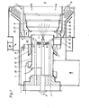
- the burner arrangement consists of an air box 1 through which a burner lance 2 for oil and several burner lances for gas are passed.
- the gas burner lances 3 are arranged around the oil burner lance 2.
- An impeller 4 is attached to the oil burner lance 2.
- the burner lance 2, 3 are surrounded by a first guide tube 5, the inlet opening 6 of which is inside the air box 1 and the outlet opening 7 of which is inside the burner mouth, which is represented by the burner throat 8.
- a combustion chamber 9 connects to the burner groove 8.
- the air box 1 is separated from the burner groove 8 by a cover plate 10 through which the first guide tube 5 projects.
- a swirl device 11 and an air guide tube 12 are provided in front of its inlet opening 6.
- the air guide tube 12 is axially adjustable via a linkage 13 guided to the outside. In one end position, the air guide tube 12 covers the air inlet cross section on the swirl device 11. In the other end position. position of the air guide tube 12, the air inlet cross section on the swirl device 11 is released and the rest of the inlet cross section to the first guide tube 5 is covered.
- the first-mentioned position of the air guide tube 12 is shown in the upper part and the other position is shown in the lower part of FIG. 1. Intermediate positions between the two end positions are also possible.
- a second guide tube 14 is arranged within the burner groove 8 in the longitudinal axis of the burner at an axial distance from the outlet opening 7 of the first guide tube 5 and the cover plate 10 of the air box 1.
- the second guide tube 14 preferably consists of a conically widening section which is adjoined by a cylindrical section.
- the second guide tube 14 is surrounded by a third guide tube 16 within the burner groove 8 at a distance, forming an annular channel 15.
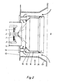
- This third guide tube 16 like the other two guide tubes 5, 14, can be metallic. Depending on the the temperatures to be expected, the third guide tube 16 can also consist of a refractory ceramic material. According to FIG. 1, the third guide tube 16 can extend into the transition of the burner groove 8 into the combustion chamber 9 or, according to FIG. 2, also end shortly before the transition. The outlet cross section of the third guide tube 16 is closer to the combustion chamber 9 than the outlet cross section of the second guide tube 14.
- the second guide tube 14 projects further into the burner groove 8 than the third guide tube 16.
- the second guide tube 14 contains an outwardly directed deflection edge 28.
- the second guide tube 14 can be provided with lateral bores 17, through which a connection between the ring channel 15 between the guide tubes 14, 16 and the interior of the second guide tube 14 is made.
- the second guide tube 14 can also be extended by a tube section 18 which partially surrounds the second guide tube 14 within the third guide tube 16. In the direction of the combustion chamber 9, the inlet opening of this pipe section 18 is present and its outlet opening behind the outlet opening of the second guide pipe 14.
- the annular channel 15 has thus been given two outlet cross sections one behind the other.
- the ring channel 15 is closed at its end facing the air box 1 and connected to the air box 1 via connecting pipes 19.
- the connecting pipes 19 can open into an air inlet chamber 20 which is formed within the air box 1 and which is open via an inlet opening to the air box 1.
- the inlet opening of the air inlet chamber 20 is adjustable via a drum slide 21 which can be axially displaced with the aid of a linkage 22. In the upper part of FIG. 1, the drum slide 21 has opened the inlet opening of the air inlet chamber 20, while in the lower part of FIG. 1 this inlet opening is closed.
- the connecting pipes open directly into the air box.
- the air inlet chamber 20 with the opening that can be adjusted via the drum slide 21 is then not present.
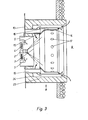
- the third guide tube 16 is arranged at a radial distance from the wall 23 of the burner groove 8 and at an axial distance from the cover plate 10 of the air box 1. In this way, an annular connecting channel 24 is created, via which the combustion chamber 9 is connected to the interior of the second guide tube 14.
- the wall 23 of the burner groove 8 can be formed by cooling pipes (FIG. 2) or be fireproof-lined (FIG. 3). Training with cooling pipes is recommended if the burner is connected to a steam generator operated in forced flow.
- the wall 23 of the burner groove 8 is surrounded by an annular chamber 25.
- the annular chamber 25 is provided with an air connection 26, through which air is conveyed into the annular chamber 25 with the aid of a pressure-increasing blower.
- the annular chamber 25 is connected to the air box 1.
- An angled baffle 27 serves to limit the annular chamber 25 laterally and is arranged at a distance from the wall 23 of the burner groove 8, the guide of the air stream cooling the wall 23.
- the ring line 29 is provided with nozzles through which water is sprayed into the connecting channel 24.
- cooling air is blown through the annular duct 15 when the burner is at a standstill.
- a cooling air line 30 is accommodated in the air box 1, which is supplied with cooling air from outside the air box 1.
- the cooling air line can also be designed as a distribution box which is connected to the annular chamber 25 shown in FIG. 1 for cooling the wall 23 of the burner groove 8.
- the cooling air line 30 is provided with pipe sockets 31 which protrude into the connecting pipes 19. The cooling air line 30 is only supplied with cooling air when the burner is at a standstill.
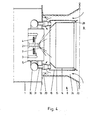
- the embodiment shown in FIG. 5 can be operated both with air as the combustion medium using the intake of combustion gas from the combustion chamber 9 and with exhaust gas from a gas turbine as the combustion medium.
- the air or the exhaust gas are optionally supplied to the air box 1.
- a drum slide 32 is arranged in the air box 1 and can be displaced in the longitudinal direction of the burner.
- the cover plate 10 ver the air box 1 to the burner groove 8 closes, is provided with an annular opening 33. This opening 33 is provided in the extension of the connecting channel 24.
- the position of the drum slide 32 shown in the lower part of FIG. 5 is selected for the operation of the burner with air as the combustion medium. In this position, the drum slide 32 closes the opening 33, as a result of which combustion gases are sucked in from the combustion chamber 9 through the connecting duct 24 in the manner described so far by the injector action of the primary air.
- the drum slide 32 When operating with exhaust gas from a gas turbine, the drum slide 32 is brought into the position shown in the upper part of FIG. 5. The drum slide 32 now opens the opening 33 so that the exhaust gas can flow through the connecting channel 24 in addition to the first guide tube 5 and the annular channel 15. In this way, a sufficiently large flow cross section is made available to the exhaust gas.
- the air volume is controlled by a control element located in the supply line.
- the combustion air is divided into a primary air component and a secondary air component.
- the primary air flows through the inner guide tube 5 and burns the fuel emerging from the oil burner lance 2 or the gas lances 3 in a flame under substoichiometric conditions.
- the secondary air enters the annular duct 15 between the first and the second guide tubes 14, 16 via the connecting tubes 19.
- the secondary air is at an axial distance via the outlet opening of the second guide tube 14 abandoned behind the primary air.
- the embodiments of the second guide tube 14 shown in FIGS. 1 and 2 split the secondary air again and add it to the flame in two successive stages.
- the secondary air emerging from the annular duct 15 is directed outwards through the deflection edge 28, ie. H. distracted away from the flame. In this way, the mixing of the secondary air with the flame gases is further delayed.
- the proportion of primary air in the total combustion air is greater than the proportion of secondary air and is between 60 and 80%, preferably about 70%.
- the quantitative division of the combustion air takes place via the drum slide 21 or by dimensioning the flow cross-sections in accordance with the division.
- the primary air is only swirled or only swirled axially or partially and partly axially parallel to the burner mouth.
- Fixed swirl devices are also possible in the path of the secondary air, so that secondary air can be supplied in an axially parallel flow or also swirled.
- the injector effect which is exerted by the primary air flowing out of the first guide tube 5, means that burned-out smoke gases are sucked out of the combustion chamber 9. These flue gases are led through the connecting channel 24 and the space between the inlet opening of the second guide tube 14 and the cover plate 10 of the air box 1 into the interior of the second guide tube 14. They come to the beginning of the flame between the primary air task and the secondary air task.
- the sucked-in flue gases can be cooled in the interior of the second guide tube 14 before they are mixed with the flame gases.
- the cooling takes place by injecting water from the ring line 29 into the flow of the sucked-in flue gases. This cooling causes the flame temperature to rise less and thus contributes to a further reduction in the formation of NO.
Landscapes
- Engineering & Computer Science (AREA)
- Chemical & Material Sciences (AREA)
- Combustion & Propulsion (AREA)
- Mechanical Engineering (AREA)
- General Engineering & Computer Science (AREA)
Priority Applications (1)
| Application Number | Priority Date | Filing Date | Title |
|---|---|---|---|
| AT84106790T ATE27854T1 (de) | 1983-07-30 | 1984-06-14 | Verfahren und brenner zum verbrennen von fluessigen oder gasfoermigen brennstoffen unter verminderter bildung von nox. |
Applications Claiming Priority (2)
| Application Number | Priority Date | Filing Date | Title |
|---|---|---|---|
| DE3327597 | 1983-07-30 | ||
| DE19833327597 DE3327597A1 (de) | 1983-07-30 | 1983-07-30 | Verfahren und brenner zum verbrennen von fluessigen oder gasfoermigen brennstoffen unter verminderter bildung von nox |
Publications (3)
| Publication Number | Publication Date |
|---|---|
| EP0139085A1 true EP0139085A1 (fr) | 1985-05-02 |
| EP0139085B1 EP0139085B1 (fr) | 1987-06-16 |
| EP0139085B2 EP0139085B2 (fr) | 1993-08-18 |
Family
ID=6205376
Family Applications (1)
| Application Number | Title | Priority Date | Filing Date |
|---|---|---|---|
| EP84106790A Expired - Lifetime EP0139085B2 (fr) | 1983-07-30 | 1984-06-14 | Procédé et brûleur pour la combustion des combustibles liquides ou gazeux avec diminution de la formation de NOx |
Country Status (5)
| Country | Link |
|---|---|
| US (1) | US4575332A (fr) |
| EP (1) | EP0139085B2 (fr) |
| JP (1) | JPH0713527B2 (fr) |
| AT (1) | ATE27854T1 (fr) |
| DE (2) | DE3327597A1 (fr) |
Cited By (7)
| Publication number | Priority date | Publication date | Assignee | Title |
|---|---|---|---|---|
| DE3600665C1 (de) * | 1986-01-13 | 1987-07-16 | Leobersdorfer Maschf | Brenner zum Verbrennen von fluessigem und/oder gasfoermigem Brennstoff unter verminderter Bildung von Stickoxiden |
| EP0386732A2 (fr) * | 1989-03-10 | 1990-09-12 | Oertli Wärmetechnik Ag | Dispositif de combustion pour brûleur à deux combustibles |
| EP0391858A1 (fr) * | 1989-04-07 | 1990-10-10 | BALSIGER, Benno | Dispositif pour la recirculation du gaz de fumée dans des brûleurs à huile et à gaz |
| WO1992016793A1 (fr) * | 1991-03-12 | 1992-10-01 | Lawrence Edward Helyer | Bruleur a faible emission de no¿x? |
| EP0525734A2 (fr) * | 1991-08-01 | 1993-02-03 | Institute of Gas Technology | Combustion cyclonique |
| EP0527565A2 (fr) * | 1991-08-09 | 1993-02-17 | Robert David Eden | Brûleur pour gaz d'échappement |
| CN106196043A (zh) * | 2016-08-31 | 2016-12-07 | 福建铁拓机械有限公司 | 用于沥青搅拌站的高效点火及燃烧的煤粉燃烧器 |
Families Citing this family (78)
| Publication number | Priority date | Publication date | Assignee | Title |
|---|---|---|---|---|
| DE3666625D1 (en) * | 1985-02-21 | 1989-11-30 | Tauranca Ltd | Fluid fuel fired burner |
| ATE42821T1 (de) * | 1985-03-04 | 1989-05-15 | Siemens Ag | Brenneranordnung fuer feuerungsanlagen, insbesondere fuer brennkammern von gasturbinenanlagen sowie verfahren zu ihrem betrieb. |
| DE3706234A1 (de) * | 1987-02-26 | 1988-09-08 | Sonvico Ag Ing Bureau | Brenner zum verbrennen von fluessigen oder gasfoermigen brennstoffen |
| US5062789A (en) * | 1988-06-08 | 1991-11-05 | Gitman Gregory M | Aspirating combustion system |
| DE3822004A1 (de) * | 1988-06-30 | 1990-01-04 | Babcock Werke Ag | Brenner |
| DE3825291A1 (de) * | 1988-07-26 | 1990-02-01 | Ver Kesselwerke Ag | Verfahren und feuerungsanlage zur verbrennung fossiler brennstoffe unter reduzierter bildung von stickoxiden |
| US4989549A (en) * | 1988-10-11 | 1991-02-05 | Donlee Technologies, Inc. | Ultra-low NOx combustion apparatus |
| US5135387A (en) * | 1989-10-19 | 1992-08-04 | It-Mcgill Environmental Systems, Inc. | Nitrogen oxide control using internally recirculated flue gas |
| US5044932A (en) * | 1989-10-19 | 1991-09-03 | It-Mcgill Pollution Control Systems, Inc. | Nitrogen oxide control using internally recirculated flue gas |
| SE464542B (sv) * | 1989-11-01 | 1991-05-06 | Aga Ab | Saett och anordning foer foerbraenning av foeretraedesvis flytande eller gasformigt fossilt braensle |
| US5275554A (en) * | 1990-08-31 | 1994-01-04 | Power-Flame, Inc. | Combustion system with low NOx adapter assembly |
| US5174743A (en) * | 1990-09-05 | 1992-12-29 | Wayne/Scott Fetzer Company | Power fuel oil burner |
| US5098282A (en) * | 1990-09-07 | 1992-03-24 | John Zink Company | Methods and apparatus for burning fuel with low NOx formation |
| US5269678A (en) * | 1990-09-07 | 1993-12-14 | Koch Engineering Company, Inc. | Methods and apparatus for burning fuel with low NOx formation |
| US5154596A (en) * | 1990-09-07 | 1992-10-13 | John Zink Company, A Division Of Koch Engineering Company, Inc. | Methods and apparatus for burning fuel with low NOx formation |
| US5092761A (en) * | 1990-11-19 | 1992-03-03 | Exxon Chemical Patents Inc. | Flue gas recirculation for NOx reduction in premix burners |
| US5096412A (en) * | 1991-01-28 | 1992-03-17 | The United States Of America As Represented By The Secretary Of The Army | Combustion chamber for multi-fuel fired ovens and griddles |
| US5462430A (en) * | 1991-05-23 | 1995-10-31 | Institute Of Gas Technology | Process and apparatus for cyclonic combustion |
| WO1992020964A1 (fr) * | 1991-05-24 | 1992-11-26 | Sci Mercimmo | Procede pour la combustion faiblement polluante d'un combustible |
| US5209187A (en) * | 1991-08-01 | 1993-05-11 | Institute Of Gas Technology | Low pollutant - emission, high efficiency cyclonic burner for firetube boilers and heaters |
| US5603906A (en) * | 1991-11-01 | 1997-02-18 | Holman Boiler Works, Inc. | Low NOx burner |
| US5257927A (en) * | 1991-11-01 | 1993-11-02 | Holman Boiler Works, Inc. | Low NOx burner |
| US5284438A (en) * | 1992-01-07 | 1994-02-08 | Koch Engineering Company, Inc. | Multiple purpose burner process and apparatus |
| US5238395A (en) * | 1992-03-27 | 1993-08-24 | John Zink Company | Low nox gas burner apparatus and methods |
| US5195884A (en) * | 1992-03-27 | 1993-03-23 | John Zink Company, A Division Of Koch Engineering Company, Inc. | Low NOx formation burner apparatus and methods |
| RU2089785C1 (ru) * | 1993-03-22 | 1997-09-10 | Холман Бойлер Уокс, Инк. | Горелка, приспособленная для снижения выделения ядовитых газов (варианты) и способ оптимизации сгорания |
| US5518395A (en) * | 1993-04-30 | 1996-05-21 | General Electric Company | Entrainment fuel nozzle for partial premixing of gaseous fuel and air to reduce emissions |
| US5350293A (en) * | 1993-07-20 | 1994-09-27 | Institute Of Gas Technology | Method for two-stage combustion utilizing forced internal recirculation |
| DE4336095A1 (de) * | 1993-10-22 | 1995-04-27 | Abb Research Ltd | Verbrennungsverfahren für atmosphärische Feuerungen und Vorrichtung zur Durchführung des Verfahrens |
| US5363782A (en) * | 1993-12-06 | 1994-11-15 | Praxair Technology, Inc. | Apparatus and process for combusting fluid fuel containing solid particles |
| US5393220A (en) * | 1993-12-06 | 1995-02-28 | Praxair Technology, Inc. | Combustion apparatus and process |
| US5636977A (en) * | 1994-10-13 | 1997-06-10 | Gas Research Institute | Burner apparatus for reducing nitrogen oxides |
| US5573391A (en) * | 1994-10-13 | 1996-11-12 | Gas Research Institute | Method for reducing nitrogen oxides |
| US5649819A (en) * | 1995-05-25 | 1997-07-22 | Gordon-Piatt Energy Group, Inc. | Low NOx burner having an improved register |
| US5709541A (en) * | 1995-06-26 | 1998-01-20 | Selas Corporation Of America | Method and apparatus for reducing NOx emissions in a gas burner |
| US5813848A (en) * | 1996-09-19 | 1998-09-29 | Loqvist; Kaj-Ragnar | Device for boilers |
| US6164956A (en) * | 1997-02-11 | 2000-12-26 | Ge Energy & Environmental Research Corporation | System and method for removing ash deposits in a combustion device |
| FR2766557B1 (fr) * | 1997-07-22 | 1999-10-22 | Pillard Chauffage | Bruleurs a combustible liquide et gazeux a faible emission d'oxydes d'azote |
| AU4694099A (en) * | 1998-06-17 | 2000-01-05 | John Zink Company Llc | Low no chi and low co burner and method for operating same |
| US20010034001A1 (en) * | 2000-02-24 | 2001-10-25 | Poe Roger L. | Low NOx emissions, low noise burner assembly and method for reducing the NOx content of furnace flue gas |
| DE10021039C2 (de) * | 2000-04-28 | 2003-04-03 | Ltg Mailaender Gmbh | Brenner sowie Verfahren zu seinem Betreiben |
| US6616442B2 (en) * | 2000-11-30 | 2003-09-09 | John Zink Company, Llc | Low NOx premix burner apparatus and methods |
| US6499990B1 (en) | 2001-03-07 | 2002-12-31 | Zeeco, Inc. | Low NOx burner apparatus and method |
| US6663380B2 (en) | 2001-09-05 | 2003-12-16 | Gas Technology Institute | Method and apparatus for advanced staged combustion utilizing forced internal recirculation |
| US7476099B2 (en) * | 2002-03-16 | 2009-01-13 | Exxonmobil Chemicals Patents Inc. | Removable light-off port plug for use in burners |
| US6893252B2 (en) | 2002-03-16 | 2005-05-17 | Exxonmobil Chemical Patents Inc. | Fuel spud for high temperature burners |
| US6890172B2 (en) | 2002-03-16 | 2005-05-10 | Exxonmobil Chemical Patents Inc. | Burner with flue gas recirculation |
| US6887068B2 (en) | 2002-03-16 | 2005-05-03 | Exxonmobil Chemical Patents Inc. | Centering plate for burner |
| US6869277B2 (en) * | 2002-03-16 | 2005-03-22 | Exxonmobil Chemical Patents Inc. | Burner employing cooled flue gas recirculation |
| US20030175634A1 (en) * | 2002-03-16 | 2003-09-18 | George Stephens | Burner with high flow area tip |
| US6893251B2 (en) | 2002-03-16 | 2005-05-17 | Exxon Mobil Chemical Patents Inc. | Burner design for reduced NOx emissions |
| US6902390B2 (en) * | 2002-03-16 | 2005-06-07 | Exxonmobil Chemical Patents, Inc. | Burner tip for pre-mix burners |
| US6881053B2 (en) * | 2002-03-16 | 2005-04-19 | Exxonmobil Chemical Patents Inc. | Burner with high capacity venturi |
| US6846175B2 (en) * | 2002-03-16 | 2005-01-25 | Exxonmobil Chemical Patents Inc. | Burner employing flue-gas recirculation system |
| US6866502B2 (en) | 2002-03-16 | 2005-03-15 | Exxonmobil Chemical Patents Inc. | Burner system employing flue gas recirculation |
| US6986658B2 (en) | 2002-03-16 | 2006-01-17 | Exxonmobil Chemical Patents, Inc. | Burner employing steam injection |
| US7322818B2 (en) * | 2002-03-16 | 2008-01-29 | Exxonmobil Chemical Patents Inc. | Method for adjusting pre-mix burners to reduce NOx emissions |
| AU2003225834A1 (en) * | 2002-03-16 | 2003-10-08 | Exxonmobil Chemical Patents Inc. | Improved burner with low nox emissions |
| US20030175635A1 (en) * | 2002-03-16 | 2003-09-18 | George Stephens | Burner employing flue-gas recirculation system with enlarged circulation duct |
| US6672859B1 (en) * | 2002-08-16 | 2004-01-06 | Gas Technology Institute | Method and apparatus for transversely staged combustion utilizing forced internal recirculation |
| US6755359B2 (en) | 2002-09-12 | 2004-06-29 | The Boeing Company | Fluid mixing injector and method |
| US6802178B2 (en) * | 2002-09-12 | 2004-10-12 | The Boeing Company | Fluid injection and injection method |
| US6775987B2 (en) | 2002-09-12 | 2004-08-17 | The Boeing Company | Low-emission, staged-combustion power generation |
| US7422427B2 (en) * | 2004-02-25 | 2008-09-09 | Coen Company, Inc. | Energy efficient low NOx burner and method of operating same |
| US7901204B2 (en) * | 2006-01-24 | 2011-03-08 | Exxonmobil Chemical Patents Inc. | Dual fuel gas-liquid burner |
| US8075305B2 (en) * | 2006-01-24 | 2011-12-13 | Exxonmobil Chemical Patents Inc. | Dual fuel gas-liquid burner |
| US7909601B2 (en) * | 2006-01-24 | 2011-03-22 | Exxonmobil Chemical Patents Inc. | Dual fuel gas-liquid burner |
| ITMI20061636A1 (it) * | 2006-08-22 | 2008-02-23 | Danieli & C Officine Meccaniche Spa | Bruciatore |
| KR100969857B1 (ko) * | 2008-11-21 | 2010-07-13 | 한국생산기술연구원 | 연료 연소장치 |
| US20120129111A1 (en) * | 2010-05-21 | 2012-05-24 | Fives North America Combustion, Inc. | Premix for non-gaseous fuel delivery |
| US20120012036A1 (en) * | 2010-07-15 | 2012-01-19 | Shaw John R | Once Through Steam Generator |
| US9593847B1 (en) | 2014-03-05 | 2017-03-14 | Zeeco, Inc. | Fuel-flexible burner apparatus and method for fired heaters |
| EP3129708B1 (fr) | 2014-04-10 | 2021-03-31 | Sofinter S.p.A. | Brûleur |
| US9593848B2 (en) | 2014-06-09 | 2017-03-14 | Zeeco, Inc. | Non-symmetrical low NOx burner apparatus and method |
| KR101931968B1 (ko) * | 2016-12-21 | 2018-12-24 | 두산중공업 주식회사 | 연도 가스 재순환 연소기를 포함하는 터빈. |
| US11353212B2 (en) | 2019-09-12 | 2022-06-07 | Zeeco, Inc. | Low NOxburner apparatus and method |
| CN217131272U (zh) * | 2020-11-25 | 2022-08-05 | 百得股份公司 | 减少排放的工业燃烧器和设备 |
| IT202000028394A1 (it) * | 2020-11-25 | 2022-05-25 | Baltur S P A | Bruciatore e apparato industriale a ridotte emissioni |
Citations (1)
| Publication number | Priority date | Publication date | Assignee | Title |
|---|---|---|---|---|
| DE2511500A1 (de) * | 1975-03-15 | 1976-09-23 | Smit Nijmegen Bv | Brenner fuer die stoechiometrische verbrennung von fluessigen brennstoffen |
Family Cites Families (14)
| Publication number | Priority date | Publication date | Assignee | Title |
|---|---|---|---|---|
| US2918117A (en) * | 1956-10-04 | 1959-12-22 | Petro Chem Process Company Inc | Heavy fuel burner with combustion gas recirculating means |
| US3781162A (en) * | 1972-03-24 | 1973-12-25 | Babcock & Wilcox Co | Reducing nox formation by combustion |
| JPS509822A (fr) * | 1973-05-31 | 1975-01-31 | ||
| US4004875A (en) * | 1975-01-23 | 1977-01-25 | John Zink Company | Low nox burner |
| JPS5218233A (en) * | 1975-08-02 | 1977-02-10 | Kawasaki Heavy Ind Ltd | Burning gas circulation-type pre-combustion chamber |
| JPS5222134A (en) * | 1975-08-12 | 1977-02-19 | Borukano Kk | Burner |
| JPS5244902U (fr) * | 1975-09-26 | 1977-03-30 | ||
| JPS5248842A (en) * | 1975-10-17 | 1977-04-19 | Fujisash Co | Suppressing process for oxidized nitrogen, and burner |
| US4130388A (en) * | 1976-09-15 | 1978-12-19 | Flynn Burner Corporation | Non-contaminating fuel burner |
| US4347052A (en) * | 1978-06-19 | 1982-08-31 | John Zink Company | Low NOX burner |
| JPS5592804A (en) * | 1978-12-30 | 1980-07-14 | Daido Steel Co Ltd | Method of burning at two-stage combustion burner |
| US4380429A (en) * | 1979-11-02 | 1983-04-19 | Hague International | Recirculating burner |
| DE3040830C2 (de) * | 1980-10-30 | 1990-05-31 | L. & C. Steinmüller GmbH, 5270 Gummersbach | Verfahren zur Verminderung der NO↓X↓ -Emission bei der Verbrennung von stickstoffhaltigen Brennstoffen |
| DE3110186A1 (de) * | 1981-03-17 | 1982-10-07 | Kawasaki Jukogyo K.K., Kobe, Hyogo | Verfahren zur verbrennung von kohlenstaub mit einem kohlenstaubbrenner |
-
1983
- 1983-07-30 DE DE19833327597 patent/DE3327597A1/de active Granted
-
1984
- 1984-06-14 AT AT84106790T patent/ATE27854T1/de not_active IP Right Cessation
- 1984-06-14 EP EP84106790A patent/EP0139085B2/fr not_active Expired - Lifetime
- 1984-06-14 DE DE8484106790T patent/DE3464283D1/de not_active Expired
- 1984-06-26 US US06/624,712 patent/US4575332A/en not_active Expired - Lifetime
- 1984-07-06 JP JP59140442A patent/JPH0713527B2/ja not_active Expired - Lifetime
Patent Citations (1)
| Publication number | Priority date | Publication date | Assignee | Title |
|---|---|---|---|---|
| DE2511500A1 (de) * | 1975-03-15 | 1976-09-23 | Smit Nijmegen Bv | Brenner fuer die stoechiometrische verbrennung von fluessigen brennstoffen |
Cited By (11)
| Publication number | Priority date | Publication date | Assignee | Title |
|---|---|---|---|---|
| DE3600665C1 (de) * | 1986-01-13 | 1987-07-16 | Leobersdorfer Maschf | Brenner zum Verbrennen von fluessigem und/oder gasfoermigem Brennstoff unter verminderter Bildung von Stickoxiden |
| EP0386732A2 (fr) * | 1989-03-10 | 1990-09-12 | Oertli Wärmetechnik Ag | Dispositif de combustion pour brûleur à deux combustibles |
| EP0386732A3 (fr) * | 1989-03-10 | 1991-05-15 | Oertli Wärmetechnik Ag | Dispositif de combustion pour brûleur à deux combustibles |
| EP0391858A1 (fr) * | 1989-04-07 | 1990-10-10 | BALSIGER, Benno | Dispositif pour la recirculation du gaz de fumée dans des brûleurs à huile et à gaz |
| WO1992016793A1 (fr) * | 1991-03-12 | 1992-10-01 | Lawrence Edward Helyer | Bruleur a faible emission de no¿x? |
| EP0525734A2 (fr) * | 1991-08-01 | 1993-02-03 | Institute of Gas Technology | Combustion cyclonique |
| EP0525734A3 (en) * | 1991-08-01 | 1993-07-14 | Institute Of Gas Technology | Cyclonic combustion |
| EP0527565A2 (fr) * | 1991-08-09 | 1993-02-17 | Robert David Eden | Brûleur pour gaz d'échappement |
| EP0527565A3 (en) * | 1991-08-09 | 1993-05-26 | Robert David Eden | Waste gas burner |
| CN106196043A (zh) * | 2016-08-31 | 2016-12-07 | 福建铁拓机械有限公司 | 用于沥青搅拌站的高效点火及燃烧的煤粉燃烧器 |
| CN106196043B (zh) * | 2016-08-31 | 2018-06-29 | 福建铁拓机械有限公司 | 用于沥青搅拌站的高效点火及燃烧的煤粉燃烧器 |
Also Published As
| Publication number | Publication date |
|---|---|
| JPH0713527B2 (ja) | 1995-02-15 |
| JPS6038513A (ja) | 1985-02-28 |
| US4575332A (en) | 1986-03-11 |
| DE3464283D1 (en) | 1987-07-23 |
| ATE27854T1 (de) | 1987-07-15 |
| DE3327597A1 (de) | 1985-02-07 |
| DE3327597C2 (fr) | 1992-07-16 |
| EP0139085B1 (fr) | 1987-06-16 |
| EP0139085B2 (fr) | 1993-08-18 |
Similar Documents
| Publication | Publication Date | Title |
|---|---|---|
| EP0139085B1 (fr) | Procédé et brûleur pour la combustion des combustibles liquides ou gazeux avec diminution de la formation de NOx | |
| DE3706234C2 (fr) | ||
| DE3306483C2 (fr) | ||
| EP0438682B1 (fr) | Système d'échappement avec filtre à particules et brûleur de régénération | |
| DE4326802A1 (de) | Brennstofflanze für flüssige und/oder gasförmige Brennstoffe sowie Verfahren zu deren Betrieb | |
| DE2602401A1 (de) | Brenner fuer fluessige und gasfoermige brennstoffe | |
| DE1551637A1 (de) | Heizvorrichtung | |
| DE4138433C2 (de) | Brenner für Industrieöfen | |
| EP1754937B1 (fr) | Tête de brûleur et procédé pour brûler du combustible | |
| DE3206074C2 (fr) | ||
| EP0348646B1 (fr) | Brûleur | |
| DE69919456T2 (de) | Brenner mit konzentrischer Luftzufuhr und zentral angeordnetem Stabilisator | |
| EP0239003B1 (fr) | Réacteur et procédé de fabrication de noir fourneau | |
| DE2511500C2 (de) | Brenner zur Verbrennung von flüssigem Brennstoff | |
| DE4244400C2 (de) | Brenner zur Heißgaserzeugung | |
| DE1083001B (de) | Verfahren und Vorrichtung zur Herstellung von Aktivruss | |
| DE4008692A1 (de) | Mischeinrichtung fuer oelgeblaesebrenner | |
| DE1401932A1 (de) | Verfahren zum Betrieb von Brennern fuer Kesselfeuerungen | |
| EP0829678A2 (fr) | Brûleur et procédé pour réchauffer un flux gazeux | |
| DE3009764A1 (de) | Kohlebrenner | |
| AT404399B (de) | Verfahren und brenner zum verbrennen insbesondere flüssiger brennstoffe | |
| DE4119278C2 (de) | Brennereinrichtung | |
| WO1998036218A1 (fr) | Bruleur a gaz ou a mazout | |
| WO1982000331A1 (fr) | Generateur de gaz chaud | |
| DE19600380A1 (de) | Brenner für flüssigen oder gasförmigen Brennstoff |
Legal Events
| Date | Code | Title | Description |
|---|---|---|---|
| PUAI | Public reference made under article 153(3) epc to a published international application that has entered the european phase |
Free format text: ORIGINAL CODE: 0009012 |
|
| AK | Designated contracting states |
Designated state(s): AT CH DE FR GB LI NL SE |
|
| 17P | Request for examination filed |
Effective date: 19850517 |
|
| GRAA | (expected) grant |
Free format text: ORIGINAL CODE: 0009210 |
|
| AK | Designated contracting states |
Kind code of ref document: B1 Designated state(s): AT CH DE FR GB LI NL SE |
|
| REF | Corresponds to: |
Ref document number: 27854 Country of ref document: AT Date of ref document: 19870715 Kind code of ref document: T |
|
| REF | Corresponds to: |
Ref document number: 3464283 Country of ref document: DE Date of ref document: 19870723 |
|
| ET | Fr: translation filed | ||
| PLBI | Opposition filed |
Free format text: ORIGINAL CODE: 0009260 |
|
| PLBI | Opposition filed |
Free format text: ORIGINAL CODE: 0009260 |
|
| PLBI | Opposition filed |
Free format text: ORIGINAL CODE: 0009260 |
|
| 26 | Opposition filed |
Opponent name: JOH. VAILLANT GMBH U. CO Effective date: 19880223 |
|
| 26 | Opposition filed |
Opponent name: EVT ENERGIE UND VERFAHRENSTECHNIK GMBH Effective date: 19880315 Opponent name: JOH. VAILLANT GMBH U. CO Effective date: 19880223 |
|
| 26 | Opposition filed |
Opponent name: L. & C. STEINMUELLER GMBH Effective date: 19880316 Opponent name: EVT ENERGIE UND VERFAHRENSTECHNIK GMBH Effective date: 19880315 Opponent name: JOH. VAILLANT GMBH U. CO Effective date: 19880223 |
|
| NLR1 | Nl: opposition has been filed with the epo |
Opponent name: JOH.VAILLANT GMBH U. CO |
|
| NLR1 | Nl: opposition has been filed with the epo |
Opponent name: L.& C. STEINMUELLER GMBH Opponent name: EVT ENERGIE UND VERFAHRENSTECHNIK GMBH |
|
| PUAH | Patent maintained in amended form |
Free format text: ORIGINAL CODE: 0009272 |
|
| STAA | Information on the status of an ep patent application or granted ep patent |
Free format text: STATUS: PATENT MAINTAINED AS AMENDED |
|
| 27A | Patent maintained in amended form |
Effective date: 19930818 |
|
| AK | Designated contracting states |
Kind code of ref document: B2 Designated state(s): AT CH DE FR GB LI NL SE |
|
| REG | Reference to a national code |
Ref country code: CH Ref legal event code: AEN |
|
| ET3 | Fr: translation filed ** decision concerning opposition | ||
| NLR2 | Nl: decision of opposition | ||
| NLR3 | Nl: receipt of modified translations in the netherlands language after an opposition procedure | ||
| EAL | Se: european patent in force in sweden |
Ref document number: 84106790.3 |
|
| PGFP | Annual fee paid to national office [announced via postgrant information from national office to epo] |
Ref country code: SE Payment date: 19950512 Year of fee payment: 12 |
|
| PGFP | Annual fee paid to national office [announced via postgrant information from national office to epo] |
Ref country code: AT Payment date: 19960529 Year of fee payment: 13 |
|
| PG25 | Lapsed in a contracting state [announced via postgrant information from national office to epo] |
Ref country code: SE Effective date: 19960615 |
|
| EUG | Se: european patent has lapsed |
Ref document number: 84106790.3 |
|
| PG25 | Lapsed in a contracting state [announced via postgrant information from national office to epo] |
Ref country code: AT Effective date: 19970614 |
|
| REG | Reference to a national code |
Ref country code: GB Ref legal event code: IF02 |
|
| PGFP | Annual fee paid to national office [announced via postgrant information from national office to epo] |
Ref country code: CH Payment date: 20020517 Year of fee payment: 19 |
|
| PGFP | Annual fee paid to national office [announced via postgrant information from national office to epo] |
Ref country code: DE Payment date: 20020527 Year of fee payment: 19 |
|
| PGFP | Annual fee paid to national office [announced via postgrant information from national office to epo] |
Ref country code: NL Payment date: 20020531 Year of fee payment: 19 |
|
| PGFP | Annual fee paid to national office [announced via postgrant information from national office to epo] |
Ref country code: GB Payment date: 20020605 Year of fee payment: 19 |
|
| PGFP | Annual fee paid to national office [announced via postgrant information from national office to epo] |
Ref country code: FR Payment date: 20020611 Year of fee payment: 19 |
|
| PG25 | Lapsed in a contracting state [announced via postgrant information from national office to epo] |
Ref country code: GB Free format text: LAPSE BECAUSE OF NON-PAYMENT OF DUE FEES Effective date: 20030614 |
|
| PG25 | Lapsed in a contracting state [announced via postgrant information from national office to epo] |
Ref country code: LI Free format text: LAPSE BECAUSE OF NON-PAYMENT OF DUE FEES Effective date: 20030630 Ref country code: CH Free format text: LAPSE BECAUSE OF NON-PAYMENT OF DUE FEES Effective date: 20030630 |
|
| PG25 | Lapsed in a contracting state [announced via postgrant information from national office to epo] |
Ref country code: NL Free format text: LAPSE BECAUSE OF NON-PAYMENT OF DUE FEES Effective date: 20040101 Ref country code: DE Free format text: LAPSE BECAUSE OF NON-PAYMENT OF DUE FEES Effective date: 20040101 |
|
| GBPC | Gb: european patent ceased through non-payment of renewal fee |
Effective date: 20030614 |
|
| REG | Reference to a national code |
Ref country code: CH Ref legal event code: PL |
|
| PG25 | Lapsed in a contracting state [announced via postgrant information from national office to epo] |
Ref country code: FR Free format text: LAPSE BECAUSE OF NON-PAYMENT OF DUE FEES Effective date: 20040227 |
|
| NLV4 | Nl: lapsed or anulled due to non-payment of the annual fee |
Effective date: 20040101 |
|
| REG | Reference to a national code |
Ref country code: FR Ref legal event code: ST |
|
| APAH | Appeal reference modified |
Free format text: ORIGINAL CODE: EPIDOSCREFNO |