EP0131270A1 - Absorbeur utilisant une matière solide pour un cycle d'absorption - Google Patents
Absorbeur utilisant une matière solide pour un cycle d'absorption Download PDFInfo
- Publication number
- EP0131270A1 EP0131270A1 EP84107877A EP84107877A EP0131270A1 EP 0131270 A1 EP0131270 A1 EP 0131270A1 EP 84107877 A EP84107877 A EP 84107877A EP 84107877 A EP84107877 A EP 84107877A EP 0131270 A1 EP0131270 A1 EP 0131270A1
- Authority
- EP
- European Patent Office
- Prior art keywords
- solid
- absorber according
- chambers
- absorber
- heat exchange
- Prior art date
- Legal status (The legal status is an assumption and is not a legal conclusion. Google has not performed a legal analysis and makes no representation as to the accuracy of the status listed.)
- Granted
Links
- 239000006096 absorbing agent Substances 0.000 title claims abstract description 148
- 239000007787 solid Substances 0.000 title claims abstract description 139
- 238000010521 absorption reaction Methods 0.000 title claims abstract description 24
- 238000005192 partition Methods 0.000 claims abstract description 24
- 238000001816 cooling Methods 0.000 claims abstract description 23
- 238000010438 heat treatment Methods 0.000 claims abstract description 19
- 239000003507 refrigerant Substances 0.000 claims abstract description 19
- 238000000034 method Methods 0.000 claims abstract description 14
- 230000008569 process Effects 0.000 claims abstract description 14
- 125000006850 spacer group Chemical group 0.000 claims description 11
- QGZKDVFQNNGYKY-UHFFFAOYSA-N Ammonia Chemical group N QGZKDVFQNNGYKY-UHFFFAOYSA-N 0.000 claims description 8
- 239000000428 dust Substances 0.000 claims description 8
- 239000007788 liquid Substances 0.000 claims description 6
- 239000010457 zeolite Substances 0.000 claims description 6
- 229910021536 Zeolite Inorganic materials 0.000 claims description 5
- HNPSIPDUKPIQMN-UHFFFAOYSA-N dioxosilane;oxo(oxoalumanyloxy)alumane Chemical compound O=[Si]=O.O=[Al]O[Al]=O HNPSIPDUKPIQMN-UHFFFAOYSA-N 0.000 claims description 5
- 229910021529 ammonia Inorganic materials 0.000 claims description 4
- 239000008187 granular material Substances 0.000 claims description 4
- 239000004033 plastic Substances 0.000 claims description 2
- XLYOFNOQVPJJNP-UHFFFAOYSA-N water Substances O XLYOFNOQVPJJNP-UHFFFAOYSA-N 0.000 claims description 2
- 229910001868 water Inorganic materials 0.000 claims description 2
- 239000004734 Polyphenylene sulfide Substances 0.000 claims 2
- 229910045601 alloy Inorganic materials 0.000 claims 2
- 239000000956 alloy Substances 0.000 claims 2
- 229910052782 aluminium Inorganic materials 0.000 claims 2
- 229920000069 polyphenylene sulfide Polymers 0.000 claims 2
- 229910000838 Al alloy Inorganic materials 0.000 claims 1
- 239000004952 Polyamide Substances 0.000 claims 1
- 239000004642 Polyimide Substances 0.000 claims 1
- XAGFODPZIPBFFR-UHFFFAOYSA-N aluminium Chemical compound [Al] XAGFODPZIPBFFR-UHFFFAOYSA-N 0.000 claims 1
- 239000000919 ceramic Substances 0.000 claims 1
- 229910000777 cunife Inorganic materials 0.000 claims 1
- 229920002647 polyamide Polymers 0.000 claims 1
- 229920001721 polyimide Polymers 0.000 claims 1
- 239000010935 stainless steel Substances 0.000 claims 1
- 238000010276 construction Methods 0.000 description 16
- 238000012546 transfer Methods 0.000 description 9
- 239000007789 gas Substances 0.000 description 7
- 230000001427 coherent effect Effects 0.000 description 6
- 238000013461 design Methods 0.000 description 6
- 238000006073 displacement reaction Methods 0.000 description 6
- 229910052751 metal Inorganic materials 0.000 description 6
- 239000002184 metal Substances 0.000 description 6
- 239000000463 material Substances 0.000 description 5
- 230000004048 modification Effects 0.000 description 4
- 238000012986 modification Methods 0.000 description 4
- 230000008901 benefit Effects 0.000 description 3
- 238000003795 desorption Methods 0.000 description 3
- 230000036961 partial effect Effects 0.000 description 3
- 230000008961 swelling Effects 0.000 description 3
- KFRRVWLBVWDFQM-UHFFFAOYSA-M [Cl-].[NH3+][Ca] Chemical compound [Cl-].[NH3+][Ca] KFRRVWLBVWDFQM-UHFFFAOYSA-M 0.000 description 2
- UCUJUFDOQOJLBE-UHFFFAOYSA-N [Cl].[Ca] Chemical compound [Cl].[Ca] UCUJUFDOQOJLBE-UHFFFAOYSA-N 0.000 description 2
- 230000015572 biosynthetic process Effects 0.000 description 2
- 238000011161 development Methods 0.000 description 2
- 230000018109 developmental process Effects 0.000 description 2
- 230000000694 effects Effects 0.000 description 2
- 230000017525 heat dissipation Effects 0.000 description 2
- 238000004519 manufacturing process Methods 0.000 description 2
- 230000005012 migration Effects 0.000 description 2
- 238000013508 migration Methods 0.000 description 2
- 238000001179 sorption measurement Methods 0.000 description 2
- 239000000126 substance Substances 0.000 description 2
- 229910000831 Steel Inorganic materials 0.000 description 1
- 230000000903 blocking effect Effects 0.000 description 1
- 239000004566 building material Substances 0.000 description 1
- 230000015556 catabolic process Effects 0.000 description 1
- 230000008859 change Effects 0.000 description 1
- 238000006243 chemical reaction Methods 0.000 description 1
- 239000000567 combustion gas Substances 0.000 description 1
- 239000002826 coolant Substances 0.000 description 1
- 238000005516 engineering process Methods 0.000 description 1
- 238000001704 evaporation Methods 0.000 description 1
- 230000008020 evaporation Effects 0.000 description 1
- 239000004744 fabric Substances 0.000 description 1
- 230000002349 favourable effect Effects 0.000 description 1
- 239000000945 filler Substances 0.000 description 1
- 239000012530 fluid Substances 0.000 description 1
- 238000009413 insulation Methods 0.000 description 1
- 239000003921 oil Substances 0.000 description 1
- 230000002829 reductive effect Effects 0.000 description 1
- 230000008929 regeneration Effects 0.000 description 1
- 238000011069 regeneration method Methods 0.000 description 1
- 230000008439 repair process Effects 0.000 description 1
- 230000000284 resting effect Effects 0.000 description 1
- 230000000717 retained effect Effects 0.000 description 1
- 230000002441 reversible effect Effects 0.000 description 1
- 235000013580 sausages Nutrition 0.000 description 1
- 239000011343 solid material Substances 0.000 description 1
- 239000010959 steel Substances 0.000 description 1
Images


Classifications
-
- F—MECHANICAL ENGINEERING; LIGHTING; HEATING; WEAPONS; BLASTING
- F25—REFRIGERATION OR COOLING; COMBINED HEATING AND REFRIGERATION SYSTEMS; HEAT PUMP SYSTEMS; MANUFACTURE OR STORAGE OF ICE; LIQUEFACTION SOLIDIFICATION OF GASES
- F25B—REFRIGERATION MACHINES, PLANTS OR SYSTEMS; COMBINED HEATING AND REFRIGERATION SYSTEMS; HEAT PUMP SYSTEMS
- F25B35/00—Boiler-absorbers, i.e. boilers usable for absorption or adsorption
- F25B35/04—Boiler-absorbers, i.e. boilers usable for absorption or adsorption using a solid as sorbent
-
- F—MECHANICAL ENGINEERING; LIGHTING; HEATING; WEAPONS; BLASTING
- F28—HEAT EXCHANGE IN GENERAL
- F28F—DETAILS OF HEAT-EXCHANGE AND HEAT-TRANSFER APPARATUS, OF GENERAL APPLICATION
- F28F3/00—Plate-like or laminated elements; Assemblies of plate-like or laminated elements
- F28F3/02—Elements or assemblies thereof with means for increasing heat-transfer area, e.g. with fins, with recesses, with corrugations
-
- Y—GENERAL TAGGING OF NEW TECHNOLOGICAL DEVELOPMENTS; GENERAL TAGGING OF CROSS-SECTIONAL TECHNOLOGIES SPANNING OVER SEVERAL SECTIONS OF THE IPC; TECHNICAL SUBJECTS COVERED BY FORMER USPC CROSS-REFERENCE ART COLLECTIONS [XRACs] AND DIGESTS
- Y02—TECHNOLOGIES OR APPLICATIONS FOR MITIGATION OR ADAPTATION AGAINST CLIMATE CHANGE
- Y02A—TECHNOLOGIES FOR ADAPTATION TO CLIMATE CHANGE
- Y02A30/00—Adapting or protecting infrastructure or their operation
- Y02A30/27—Relating to heating, ventilation or air conditioning [HVAC] technologies
-
- Y—GENERAL TAGGING OF NEW TECHNOLOGICAL DEVELOPMENTS; GENERAL TAGGING OF CROSS-SECTIONAL TECHNOLOGIES SPANNING OVER SEVERAL SECTIONS OF THE IPC; TECHNICAL SUBJECTS COVERED BY FORMER USPC CROSS-REFERENCE ART COLLECTIONS [XRACs] AND DIGESTS
- Y02—TECHNOLOGIES OR APPLICATIONS FOR MITIGATION OR ADAPTATION AGAINST CLIMATE CHANGE
- Y02B—CLIMATE CHANGE MITIGATION TECHNOLOGIES RELATED TO BUILDINGS, e.g. HOUSING, HOUSE APPLIANCES OR RELATED END-USER APPLICATIONS
- Y02B30/00—Energy efficient heating, ventilation or air conditioning [HVAC]
- Y02B30/62—Absorption based systems
Definitions
- a refrigerant in vapor form is supplied to the absorber material of an absorber, which serves as the working medium, and is absorbed or adsorbed in it. This releases heat of absorption or adsorption. This heat of reaction is dissipated via a cooling heat exchange medium.
- the absorber material can be regenerated by supplying heat by means of a heating heat exchange medium.
- the refrigerant is expelled, liquefied in a downstream condenser and fed to an evaporator under reduced pressure, from which the refrigerant can be fed back to the regenerated absorber in a cycle after evaporation.
- Such a cycle can be used in different ways. The best known is the use as an absorption heat pump, as an absorption refrigerator or as a heat transformer.
- the refrigerant is supplied to the absorber solid on one side and removed from the absorber solid on an opposite side. Two different steam rooms are thus provided for the absorption and desorption of the refrigerant.
- the invention is concerned with the second type of construction, in which a single vapor space serves alternately as an absorber vapor space and as a desorber vapor space. This second type of construction already offers advantages because it saves a second steam room.
- the invention proceeds generically from a refrigerator by Homann-Werke, Wuppertal, according to Figs. 257 and 258 of the monograph R. Plank / Kuprianoff "The small refrigerator", Springer Verlag Berlin, Göttingen, Heidelberg, 2nd improved edition, 1960, p. 351 to 359, especially from p. 355 under no. 3.
- the chlor-calcium-ammonia system is used as the working fluid-refrigerant pair.
- the chlorine calcium is filled into elongated vertical chambers open on its upper face, which are formed by stamped and welded steel sheets.
- the ammonia vapor fills you Vapor space, which is composed of vacant end sections of the chambers.
- the heat transfer from the radially inner end face is inhibited by the fact that this end face is the smallest area in relation to the remaining outer chamber surface.
- the cooling from the outside is inhibited by the fact that heat-conducting contact over the entire circumferential surface of the chambers with the outer ribbed heat exchange body only occurs when the absorber solid swells completely and then the heat conduction between the outer heat exchanger and the inner ones Partial sheet metal is still disturbed by at least a large circumferential intermediate absorption masses of low conductivity. After the swelling of the absorber solid, the vapor space is largely filled with a porous mass that is not returned between the metal sheets and leads to considerable pressure drops in the vapor space.
- the respective chamber depth can only be very small, since steam spaces and pressurization spaces alternate with the heat exchange medium on the two flat sides of the chambers and therefore the heat flow only enters or enters the chamber from one flat side from this exits.
- the narrow sides of the chambers can be neglected. Despite the breakdown into individual units per unit, this requires a relatively high level of construction.
- the object of the invention is to find a new way of fulfilling the four requirements mentioned as optimally as possible.
- the design of the steam space as a preferably coherent steam space as well as the interconnection of the solid absorber can be retained.
- the chamber depth can be optimally adjusted to the desired period of material exchange.
- the heat inflow and outflow take place from both sides of the chamber, so that the chamber width can be selected twice as large as the plate thickness of DE-OS 30 16 290 without loss of heat supply or heat dissipation.
- the length dimension remains freely selectable without impairing the properties and can thus be adapted to the desired amount of solid absorber without having to increase the number of chambers for this purpose. It is therefore not even necessary to take full advantage of the chamber depth from the point of view of the material exchange, since there are expansion options in another direction, so one can in particular keep the chamber depth very small so that only one in the direction of the chamber depth to get a small pressure drop.
- the two alternative solutions of the invention - which can also be coupled to one another, as will be explained later in a preferred exemplary embodiment - see either direct or indirect cooling or heating of the side walls of the internal chambers, that is to say the intermediate walls of the adjacent chambers, in front.
- Direct cooling is more intensive than indirect cooling.
- the greater construction costs with direct cooling can, however, be at least partially compensated for by working with larger chamber widths.
- the ratio of solid absorber mass to mass of the heat exchanger is favorable in the sense of requirement 3.
- Requirements 1 and 2 can be optimally fulfilled.
- the requirement 4. is met at least in principle by free availability on the one hand of the width dimension (number of chambers) and of the length dimension on the other hand.
- Claim 2 describes a structurally particularly simple embodiment of a solid absorber with indirect cooling, i.e. by means of cooling over a significant heat-conducting intermediate section.
- claim 3 specifies the possibility of guiding the heat exchange medium in at least one channel.
- this channel can be a flow channel or other gas channel for a gaseous heat exchange medium (cf. claim 10).
- the channel formation comes into question for liquid heat exchange media or even for the inclusion of a heat exchange medium designed as resistance heating.
- Claim 4 shows that you can combine the construction of a finned heat exchanger with that of a heat exchanger forming a channel.
- each chamber is assigned its own channel.
- the channels can serve to accommodate different types of heat exchange media (cf. claim 6 and claim 7).
- Claim 8 specifies a special feature, according to which an alternating function of successive channels can also be provided, in particular in order to be able to heat and cool alternately via the successive channels.
- Solar energy can also serve as the heating heat exchange medium, in which case the heat-absorbing surface is to be designed in the manner of solar collectors.
- the solid absorber according to the invention When the solid absorber according to the invention is designed as a fin heat exchanger, it preferably forms an extruded profile (claim 11). This means a particularly simple production method.
- each individual flat tubes (claims 18 and 19). These can form a limit case of a shell-and-tube heat exchanger according to claim 20. Above all, such individual flat tubes enable a structure similar to a finned heat exchanger, so that the cuboid chambers generally desired according to the invention can be formed.
- the intermediate walls designed as hollow lines are formed by tubes distributed along the respective intermediate wall (claims 14 to 16). This is particularly easy to implement constructively. The simplest construction is obtained using round tubes.
- flat tubes can also be used, the flat side expediently extending in the direction of the chamber depth. For example, oval tubes are possible.
- the tubes can touch each other to build the partition; however, a mutual distance is preferred, so that the partitions only partially separate the chambers lying between them.
- the side of the partition walls not facing the chamber, in particular the gaps between the tubes, is then expediently covered or fulfilled by a thin layer of the absorber solid (claims 12 to 14).
- Hollow pipes can also be achieved according to claim 21 in that the chambers and channels are formed by a cross-flow plate heat exchanger.
- the second type of construction makes it possible, according to claim 22, to have both end faces of the chambers communicate with one vapor space each.
- the difference to the first type of construction is that these two steam rooms communicate with each other, so that practically the chamber connected with its two end faces to each steam room represents the tandem arrangement of two chamber volumes, each of which is only connected to a single assigned steam room, but at the same time are arranged one behind the other.
- the mass transfer limit migrates from a vapor space to the middle depth of the chamber and then migrates back again while it is at a fest fabric absorbers of the first type migrate through the entire chamber from one steam room to another.
- the device period determined by the migration of the mass transfer limit is only related to half the depth of the chamber, in the first construction type to the entire depth.
- the side of the intermediate walls not facing the chamber is preferably covered by a thin layer of the absorber solid.
- absorber solid material arranged in this thin layer can be adequately cooled or heated from the end face of the intermediate wall. If such a thin layer is arranged on the side facing away from the vapor space and there is not another vapor space in tandem arrangement, the absorber solid can also serve as heat insulation means for the subsequent mechanical construction of the solid absorber.
- Claim 14 fulfills these conditions optimally.
- the solid absorber according to the invention also makes it possible to fill the absorber solid loosely into open-topped chambers. Then, however, one is restricted with regard to the spatial alignment in the practical absorption cycle process as well as with transport.
- a completely invariant spatial arrangement enables the absorber solid to be sealed off from the steam space by means of a lattice work according to claim 23 with the advantageous further development according to claim 24; after that the function of holding down the intact granulate is prevented by a coarse support grid and the blocking function against the migration of dust-like absorber solids into the vapor space and subsequent lines fulfilled by a dust screen that is still permeable to the coolant vapor, and the dust screen, which is generally mechanically very resistant, can itself be held down by the support grille.
- the vapor space is preferably designed to be coherent with low throttling in such a way that essentially all of the chambers have the same vapor pressure of the refrigerant. This can be achieved in particular by means of a relatively large-volume coherent steam space, which is located opposite all the chambers.
- Claims 26 to 30 relate to some preferred structural designs.
- Claim 30 once again emphasizes the cuboid shape of the chambers, which is particularly sought after according to the invention, but which is accessible to a certain extent without major modifications to the principle of operation of the invention.
- the respective axis of at least the inner chambers is curved in their depth direction (claim 32).
- This can be realized particularly easily if intermediate walls designed as hollow walls are constructed from a plurality of tubes, as provided in claims 15 to 17. Then these tubes, which form a common partition, can be arranged offset from one another (claim 33). This can be done, for example, in such a way that the pipes are arranged offset to a gap (claim 34).
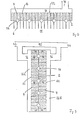
- the heat exchanger 1 has a finned heat exchanger as the heat exchanger, which is formed by an extruded profile. This has a central plate 2, on both sides of which lamellar ribs 4 and 6 are formed.
- the ribs 4 and the ribs 6 are each equidistant. For manufacturing reasons, it is also advantageous if the ribs 4 and 6 lie opposite one another; however, this is not absolutely necessary for functional reasons.
- the plate 2 forms, together with a U-profile 8 resting on it, a rectangular shaft into which the ribs 6 distributed over it protrude and which serves as a gas channel or gas fireplace 10 perpendicular to the plane of the drawing.
- Alternating cooling and heating gaseous heat exchange medium can be passed through this, for example cooling air and combustion gases moved alternately by a fan.
- a number of comb-like turbulence plates 12 are distributed over the gas channel 10 parallel to the plane of the drawing, which are fastened to the elongated flat U-profile 8 and with a distance from the fins 6 and the plate 2 the ribs 6 are arranged intermeshing.
- the ribs 4 divide from each other cuboid chambers of the same dimensions. This creates two side chambers 14 and chambers 16 of identical dimensions, each with an adjacent chamber 14 on each side or have 16.
- the chambers have a depth (or height) h, a width b and a length e perpendicular to the plane of the drawing, which can be indefinite and in particular very long.
- the width of the two side chambers 14 is approximately b / 2.
- the chambers 14 and 16 are filled with absorber solid 18, in particular zeolite, which does not swell when absorbing a refrigerant, does not deform at all and is dimensionally stable, granular or sausage-shaped.
- the absorber solid 18 also forms a thin layer 20 which covers the free edges of the ribs 4 and has a thickness of at most b / 2, here a significantly lower thickness.
- the absorber solid is held down in the direction of the chambers 14 and 16 by a latticework 22, which is only indicated schematically by a dashed line.
- This latticework 22 consists of a fine dust sieve facing the chambers, preferably made of metal, which is impermeable to dust from absorber solid, but is permeable to refrigerant vapor and can be flexible.
- the absorber solid 18 and the dust sieve are held down by a coarse support grid.
- the support grid is in turn supported by several local spacers 24 distributed over the plate length.
- spacers 24 can for example be button-shaped, column-shaped or, as shown, short U-profiles with external bevels. It is essential that the spacers 24 do not extend over the entire length of the chambers, but leave a coherent vapor space 26 on the chamber side facing away from the plate 2.
- the spacers 24 are in turn supported on a cover 28 designed as a flat, rectangular pot, which can be releasably attached to the plate 2 opposite the U-profile 8.
- cover 28 designed as a flat, rectangular pot, which can be releasably attached to the plate 2 opposite the U-profile 8.
- they can also be formed integrally with the cover 28, for example as deep-drawn sections.
- the cover 28 can also be detachable again after it has been fastened to the plate 2, although this can also have advantages for filling in the absorber solid and for carrying out any repair work. Since the filled solid absorber is very durable, the lid can also be permanently attached, for example welded to the fin heat exchanger.
- the steam chamber 26 has two pipe connections 32 and 34.
- the pipe connection 32 which has a slightly larger internal cross section than the pipe connection 34, can be connected to an evaporator (not shown) and the pipe connection 34 can be connected to a condenser (not shown) of a periodically operating absorption cycle process.
- the condenser and evaporator are alternately connected to the steam chamber 26, while the other connection is blocked during this time.
- the valves provided for this purpose are to be thought of in addition to the connections 32 and 34.
- the chambers 14 and 16 are expediently not filled from the side of the later steam space, but in the direction of the width of the chambers with subsequent distribution in the direction of the length of the chambers.
- the individual ribs 4 serving as partitions of the chambers can be cut back somewhat in this direction and thus gain a common filling space which can be fed through a closable outer filler neck. This makes it possible to prefabricate the entire arrangement, including the latticework, and only then to fill it with the absorber solid.
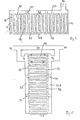
- connection 36 instead of separate connections 32 and 34, it is also possible to provide a common line connection 36, as is illustrated in the exemplary embodiment according to FIG. 2 without restricting generality.
- the pipe connection 36 will be followed by a two-way valve arrangement in the direction of the evaporator and the condenser, which is operated in push-pull mode.
- the basic structure of the solid absorber according to FIG. 2 is otherwise the same as that according to FIG. 1.
- the only special feature is that cylindrical channels 38 are formed in the plate 2 at their crossing point with ribs 4 and 6, each of which is at a distance from several chambers 16 successive.
- a channel 38 is assigned to four chambers 16 and 14, respectively.
- Such channels 38 can be used differently. On the one hand, they can accommodate one type of heat exchange medium, for example the heating heat exchange medium, while the fins 6 are acted upon by a cooling air stream as before. However, one can also apply a heating current to the fins 6 and guide a cooling heat exchange medium in the channels 38. Finally, the channels 38 can be used to enhance the effect of a heat exchange medium acting on the ribs 6, for example applying a heating air flow to the ribs 6 and additionally applying thermal energy in the channels 38 by means of a liquid heat exchange medium or by means of an introduced resistance heater. Finally, it is possible to have the type of application of heat alternate in the individual channels along the plate 2 in the width direction and to switch on alternately. Of course, it is also possible to alternately apply the same channel 38 with different heat exchange medium.
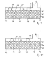
- FIG. 3 shows a further development of FIG. 2.
- the channels 38 are provided solely for the application of the cooling and heating heat exchange medium.
- the arrangement with alternating use of the channels 38 is particularly preferred, in order to be able to avoid switching processes in which individual channels are acted upon.
- this arrangement enables two rows of chambers 14 and 16 to be provided, which are common on both sides seeds plate 2 are arranged and are each separated by ribs 4 serving as partitions.
- ribs 4 are drawn here to illustrate that they do not have to lie opposite one another, somewhat offset from one another. A corresponding displacement is of course also possible in the other exemplary embodiments with regard to the ribs 4 and 6, to be precise up to half the displacement.
- the steam space is formed here by two separate partial steam spaces 26a and 26b, which communicate with one another practically free of pressure drops via a connecting line 40.
- the connecting line 40 is in each case connected to the steam space 26a or 26b via a connection 36 and can be connected to the evaporator or condenser of the absorption circuit via corresponding line devices 42 and 44. To the outside, the connections 42 and 44 take over the function of the connections 32 and 34.
- the same arrangement can also be provided when interconnecting heat exchangers according to FIG. 1.
- the end faces of the respective chambers 14 and 16 of the two rows facing away from the plates 2 are connected to a common vapor space 26, which in turn can be alternately connected via a line connection 36 to an evaporator and a condenser of the absorber circuit, as by the two reference numerals 42 and 44 are indicated.
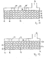
- FIGS. 4, 5 and 7 relate to solid absorbers with flat tube-tube bundle heat exchangers.
- the outer chambers 14 and the inner chambers 16 are separated from one another by flat tubes 46, which are essentially elongated and rectangular, and which, in a manner not shown, can be fed from common tube sheets with heat exchange medium, preferably heat exchange liquid, in a manner not shown, as is customary with shell-and-tube heat exchangers.
- heat exchange medium preferably heat exchange liquid
- heat transfer oils can be used here.
- a plate 2 is no longer required, nor is a ribbing with fins 6 intended for indirect heat transfer.
- finned heat exchangers according to FIGS. 1 to 3 and 6 could also be modified such that 4 flat tubes 46 instead of the fins 4 occur if one should again strive for a combined heating and cooling effect, which should follow directly and at the same time indirectly, for example.
- this combination option will no longer be considered in detail below.
- the part of the housing of the solid absorber according to FIG. 1 still remains which surrounds the vapor space 26 and which can be supplemented with a housing base part 48.
- the same also applies to the arrangement according to FIG. 3.
- a further thin layer 50 is arranged here, which is arranged between the free edges of the flat tubes 46 and the base part 48, which are distant from the vapor space 26 and in turn preferably has a thickness of approximately or at most half the width b of the chambers.
- two-row arrangements of the type of FIG. 4 can also be interconnected.
- plate 2 is no longer required here, the two chambers 14 and 16 of each row can be directly connected, so that here two chambers with the total depth 2h follow each other without a change in function and the thin layer 50 and the base part 48 can be dispensed with.
- a cross-flow plate heat exchanger can also be used as shown in FIG. 8 for chamber formation for the absorber solid of the solid absorber.
- the duct system guided in one direction along the ducts can alternatively accommodate the cooling or heating heat exchange medium, as indicated by arrows 52.
- the plate interspaces of the nested alternative flow system are essentially filled with the absorber solid 18 and closed off by means of the lattice work 22 from a vapor space which is connected to a line connection 36 and in accordance with the opposite arrows, which correspond to the connections 42 and 44, alternately according to the arrow 42 leading in can be connected to the evaporator or leading arrow 44 to the condenser.
- you can also fill up on both ends of the Systems provide two separate steam rooms, which are connected in the manner of FIGS. 3 and 5 by a connecting line 40 inside or outside the housing.
- two external chambers 14 and a plurality of internal chambers 16, but at least one internal chamber, are arranged in a row next to one another and divided by partitions, which in the case of FIGS
- three round tubes 62 and in the case of FIGS. 11 and 12 are formed by four round tubes 62 and each replace a single flat tube 46 according to FIG. 4.
- the round tubes 62 can in turn be flowed through by a heat exchange fluid and are combined in the usual manner in terms of flow at their ends led out of the plane of the drawing, e.g. through conventional tube sheets.
- the chambers 14 and 16 are filled with absorber solid 18, for example zeolite granules.
- This solid absorber extends from a horizontal base part 48 of the solid absorber 18 to the opposite flat interface to a vapor which can be acted upon by the refrigerant vapor room 26, which is connected via a line connection 36 to the absorption cycle process.
- Spacers 24 are fastened to a latticework 22 which serves to hold down the absorber solid 18 and extends along the boundary surface of the absorber solid 18 facing the vapor space.
- the spacers are supported on the side of the solid absorber housing facing away from the absorber solid 18, which e.g. can be shaped analogously to the base part 48, but e.g. can also be a cover as in other exemplary embodiments.
- the latticework 22 can be composed of a fine dust sieve facing the chambers and a coarse support grille facing the steam space, the coarse support grate being expediently connected to the spacers.
- the dust screen can also be attached to the support grid; however, it is sufficient to loosely clamp it between the support grid and the absorber solid.
- a coherent thin layer 50 of the absorber solid 18 extends on the base part 48.
- a coherent thin layer 20 of the absorber solid 18 extends under the latticework 22.
- these two layers which lie opposite the surfaces of the intermediate walls between the chambers that do not face the chambers. these chambers are partially connected.
- each partition wall can also be moved towards one another until they come into contact with one another, so that the gaps 60 disappear.
- the tubes 62 are also round tubes. You could also use single flat tubes, e.g. Oval tubes, replace.
- the flat tubes are expediently arranged with their larger diameter in the direction of the respective partition.
- the embodiment according to FIG. 12 differs from that according to FIG. 10 in that when four round tubes 62 are arranged per partition wall of the tube arrangement of FIG. 10, a tube 62b is also arranged in front of the thin layer 20, the tubes 62b are arranged above the tubes 62a. Likewise, the two remaining tubes 62 of each partition are arranged one above the other. As a result, the still approximately cuboid shape of the inner chambers 16 is modified into a somewhat serpentine shape. In addition, as in FIG. 11, the gaps between the tubes have narrowed or, in the borderline case, completely disappeared.
Landscapes
- Engineering & Computer Science (AREA)
- Physics & Mathematics (AREA)
- Thermal Sciences (AREA)
- Mechanical Engineering (AREA)
- General Engineering & Computer Science (AREA)
- Sorption Type Refrigeration Machines (AREA)
- Heat-Exchange Devices With Radiators And Conduit Assemblies (AREA)
Priority Applications (1)
| Application Number | Priority Date | Filing Date | Title |
|---|---|---|---|
| AT84107877T ATE38282T1 (de) | 1983-07-08 | 1984-07-05 | Feststoffabsorber fuer einen absorptionskreisprozess. |
Applications Claiming Priority (4)
| Application Number | Priority Date | Filing Date | Title |
|---|---|---|---|
| DE3324745 | 1983-07-08 | ||
| DE3324745A DE3324745C1 (de) | 1983-07-08 | 1983-07-08 | Feststoffabsorber für einen Absorptionskreisprozeß |
| DE3424116 | 1984-06-29 | ||
| DE3424116A DE3424116C2 (de) | 1984-06-29 | 1984-06-29 | Feststoffabsorber für einen Absorptionskreisprozeß |
Publications (2)
| Publication Number | Publication Date |
|---|---|
| EP0131270A1 true EP0131270A1 (fr) | 1985-01-16 |
| EP0131270B1 EP0131270B1 (fr) | 1988-10-26 |
Family
ID=25812159
Family Applications (1)
| Application Number | Title | Priority Date | Filing Date |
|---|---|---|---|
| EP84107877A Expired EP0131270B1 (fr) | 1983-07-08 | 1984-07-05 | Absorbeur utilisant une matière solide pour un cycle d'absorption |
Country Status (3)
| Country | Link |
|---|---|
| US (1) | US4581049A (fr) |
| EP (1) | EP0131270B1 (fr) |
| DE (1) | DE3474852D1 (fr) |
Cited By (5)
| Publication number | Priority date | Publication date | Assignee | Title |
|---|---|---|---|---|
| FR2593588A1 (fr) * | 1986-01-28 | 1987-07-31 | Nishiyodo Air Conditioner | Machine frigorifique a adsorption |
| FR2610999A1 (fr) * | 1987-02-17 | 1988-08-19 | Centre Nat Rech Scient | Compresseur cryogenique a absorption et ins- tallation de refrigeration en faisant application |
| FR2665516A1 (fr) * | 1990-08-02 | 1992-02-07 | Blaizat Claude | Structure particuliere d'acceleration de la vitesse de reactivite de la zeolithe et procede de depot de la zeolithe sur ladite structure. |
| EP1046870A3 (fr) * | 1999-04-20 | 2002-01-30 | ZEO-TECH Zeolith Technologie GmbH | Procédé pour le réchauffement et le refroidissement d'un sorbeur |
| WO2007017274A2 (fr) | 2005-08-10 | 2007-02-15 | Fraunhofer-Gesellschaft zur Förderung der angewandten Forschung e.V. | Ensemble de plaques d'echange thermique en contact thermique avec un adsorbant |
Families Citing this family (37)
| Publication number | Priority date | Publication date | Assignee | Title |
|---|---|---|---|---|
| FR2585812B1 (fr) * | 1985-07-30 | 1987-10-23 | Jeumont Schneider | Machine thermique a adsorption-desorption |
| DE3532093C1 (de) * | 1985-09-09 | 1987-04-09 | Schiedel Gmbh & Co | Diskontinuierlich arbeitende Sorptions-Speichervorrichtung mit Feststoffabsorber |
| DE3837880A1 (de) * | 1988-11-08 | 1990-05-10 | Zeolith Tech | Kuehlbehaelter fuer einen sorptionsapparat |
| US5441716A (en) * | 1989-03-08 | 1995-08-15 | Rocky Research | Method and apparatus for achieving high reaction rates |
| US5664427A (en) * | 1989-03-08 | 1997-09-09 | Rocky Research | Rapid sorption cooling or freezing appliance |
| US5598721A (en) * | 1989-03-08 | 1997-02-04 | Rocky Research | Heating and air conditioning systems incorporating solid-vapor sorption reactors capable of high reaction rates |
| DE69019344T2 (de) * | 1989-03-08 | 1995-10-19 | Rocky Research, Boulder City | Vorrichtung und verfahren zur erhaltung von hohen reaktionsleistungen in fest-gas-reaktorsystemen. |
| US5628205A (en) * | 1989-03-08 | 1997-05-13 | Rocky Research | Refrigerators/freezers incorporating solid-vapor sorption reactors capable of high reaction rates |
| US5110328A (en) * | 1989-06-07 | 1992-05-05 | Kabushiki Kaisha Kobe Seiko Sho | Solvent adsorber and solvent recovery system |
| FR2679633B1 (fr) * | 1991-07-26 | 1997-12-12 | Faiveley Sa | Installation pour produire du froid par reaction solide/gaz, le reacteur comportant des moyens de refroidissement. |
| US5855119A (en) | 1995-09-20 | 1999-01-05 | Sun Microsystems, Inc. | Method and apparatus for cooling electrical components |
| IL123603A (en) * | 1995-09-20 | 2000-07-16 | Sun Microsystems Inc | Absorbent pair refrigeration system |
| US5916259A (en) | 1995-09-20 | 1999-06-29 | Sun Microsystems, Inc. | Coaxial waveguide applicator for an electromagnetic wave-activated sorption system |
| US5873258A (en) * | 1995-09-20 | 1999-02-23 | Sun Microsystems, Inc | Sorption refrigeration appliance |
| US5842356A (en) * | 1995-09-20 | 1998-12-01 | Sun Microsystems, Inc. | Electromagnetic wave-activated sorption refrigeration system |
| US6244056B1 (en) | 1995-09-20 | 2001-06-12 | Sun Microsystems, Inc. | Controlled production of ammonia and other gases |
| US5862855A (en) * | 1996-01-04 | 1999-01-26 | Balk; Sheldon | Hydride bed and heat pump |
| US5917140A (en) * | 1996-05-21 | 1999-06-29 | Advanced Technology Materials, Inc. | Sorbent-based fluid storage and dispensing vessel with enhanced heat transfer means |
| GB9613211D0 (en) * | 1996-06-24 | 1996-08-28 | Johnson Matthey Plc | Improvements in heat transfer materials |
| US5861050A (en) * | 1996-11-08 | 1999-01-19 | Store Heat And Produce Energy, Inc. | Thermally-managed fuel vapor recovery canister |
| JP4574783B2 (ja) * | 2000-03-07 | 2010-11-04 | 株式会社豊田自動織機 | 水素吸蔵合金タンク |
| US7003979B1 (en) | 2000-03-13 | 2006-02-28 | Sun Microsystems, Inc. | Method and apparatus for making a sorber |
| US6502419B2 (en) * | 2000-04-13 | 2003-01-07 | Sun Microsystems, Inc. | Electro-desorption compressor |
| ES2281441T3 (es) * | 2000-07-06 | 2007-10-01 | Thermagen S.A. | Dispositivo de refrigeracion por absorcion. |
| FR2816698B1 (fr) * | 2000-11-13 | 2004-05-28 | Pierre Jeuch | Dispositif de refrigeration par adsorption |
| US6923018B1 (en) * | 2001-04-12 | 2005-08-02 | Sun Microsystems, Inc. | Electro-desorption actuator |
| US6508862B1 (en) * | 2001-04-30 | 2003-01-21 | Battelle Memorial Institute | Apparatus and methods for separation/purification utilizing rapidly cycled thermal swing sorption |
| JP4220762B2 (ja) * | 2002-11-15 | 2009-02-04 | 株式会社豊田自動織機 | 固体充填タンク |
| US6895780B1 (en) * | 2003-06-30 | 2005-05-24 | Sun Microsystems, Inc. | Sorber structure for electro-desorption compressor |
| GB0617721D0 (en) * | 2006-09-08 | 2006-10-18 | Univ Warwick | Heat exchanger |
| DE102007012113B4 (de) * | 2007-03-13 | 2009-04-16 | Sortech Ag | Kompakte Sorptionskälteeinrichtung |
| GB2471841A (en) | 2009-07-13 | 2011-01-19 | Univ Warwick | Shell and tube heat exchanger containing a sorbent |
| FR2952695B1 (fr) * | 2009-11-13 | 2012-03-30 | Commissariat Energie Atomique | Reservoir de stockage d'hydrogene a hydrures metalliques |
| US8701426B2 (en) * | 2011-04-28 | 2014-04-22 | Lockheed Martin Corporation | Enhanced boiler |
| JP6232196B2 (ja) * | 2013-03-21 | 2017-11-15 | 株式会社豊田中央研究所 | 箱体、化学蓄熱反応器及び化学蓄熱システム |
| US20160290685A1 (en) * | 2015-03-30 | 2016-10-06 | Yasutomo Aman | Heat storage and release unit, chemical heat pump, and non-electrified cooling unit |
| EP3299759A1 (fr) * | 2016-09-21 | 2018-03-28 | Nederlandse Organisatie voor toegepast- natuurwetenschappelijk onderzoek TNO | Système et procédé de stockage thermochimique d'énergie |
Citations (14)
| Publication number | Priority date | Publication date | Assignee | Title |
|---|---|---|---|---|
| DE363826C (de) * | 1916-06-08 | 1922-11-14 | Seay Syndicate Ltd | Absorptionskaelteverfahren |
| CH114978A (de) * | 1924-02-22 | 1926-05-17 | Ivar Amundsen | Absorptions-Kühlanlage. |
| DE554766C (de) * | 1927-02-19 | 1932-07-14 | Wulff Berzelius Normelli | Periodische Absorptionskaeltemaschine |
| DE585880C (de) * | 1932-04-10 | 1933-10-14 | Siemens Schuckertwerke Akt Ges | Kocherabsorber fuer periodisch wirkende Kaeltemaschinen |
| FR776919A (fr) * | 1934-08-08 | 1935-02-07 | Absorbeur régénérateur pour installations frigorifiques | |
| DE623182C (de) * | 1933-02-04 | 1935-12-14 | Siemens Schuckertwerke Akt Ges | Kocherabsorber fuer periodisch wirkende Absorptionsapparate |
| US2253907A (en) * | 1936-12-15 | 1941-08-26 | Julius Y Levine | Refrigerating apparatus |
| US2326130A (en) * | 1938-11-21 | 1943-08-10 | Kleen Nils Erland Af | Refrigerator |
| FR923016A (fr) * | 1946-02-28 | 1947-06-25 | Procédé de réfrigération par absorption et machine pour la mise en oeuvre de ce procédé | |
| FR1018022A (fr) * | 1950-04-08 | 1952-12-24 | Fr De Realisations Metalliques | Appareil frigorifique à absorption |
| GB2010468A (en) * | 1977-12-14 | 1979-06-27 | Wallsten H | A Heat Storage Element and a Method of Manufacturing the Same |
| FR2455713A1 (fr) * | 1979-04-30 | 1980-11-28 | Wallsten Hans | Dispositif contenant un corps sorbeur et procede de fabrication correspondant |
| EP0061191A1 (fr) * | 1981-03-23 | 1982-09-29 | Sekisui Kagaku Kogyo Kabushiki Kaisha | Réacteur à hydrures métalliques |
| EP0064562A1 (fr) * | 1981-05-06 | 1982-11-17 | Sekisui Kagaku Kogyo Kabushiki Kaisha | Réacteur à hydride métallique |
Family Cites Families (9)
| Publication number | Priority date | Publication date | Assignee | Title |
|---|---|---|---|---|
| DE612169C (de) * | 1931-02-09 | 1935-04-15 | Thore Martin Elfving | Intermittierend arbeitende Absorptionskaeltemaschine |
| US2323902A (en) * | 1937-07-16 | 1943-07-13 | Kleen Nils Erland Af | Absorption or adsorption refrigerating apparatus |
| DE814158C (de) * | 1950-04-01 | 1951-10-31 | Homann Werke Wilhelm Homann | Periodisch wirkende, insbesondere trockene Absorptionskaeltemaschine |
| US3264803A (en) * | 1963-01-21 | 1966-08-09 | Gen Electric | Sorption vacuum pump |
| US3296773A (en) * | 1964-03-24 | 1967-01-10 | Union Carbide Corp | Adsorbent-coated thermal panels |
| US3335550A (en) * | 1964-04-24 | 1967-08-15 | Union Carbide Corp | Cryosorption apparatus |
| US4034569A (en) * | 1974-11-04 | 1977-07-12 | Tchernev Dimiter I | Sorption system for low-grade (solar) heat utilization |
| JPS52134875A (en) * | 1976-05-08 | 1977-11-11 | Daikin Ind Ltd | Continuous adsorber by use of activated carbon |
| US4377398A (en) * | 1977-04-21 | 1983-03-22 | Motorola Inc. | Heat energized vapor adsorbent pump |
-
1984
- 1984-07-05 DE DE8484107877T patent/DE3474852D1/de not_active Expired
- 1984-07-05 EP EP84107877A patent/EP0131270B1/fr not_active Expired
- 1984-07-06 US US06/628,654 patent/US4581049A/en not_active Expired - Fee Related
Patent Citations (14)
| Publication number | Priority date | Publication date | Assignee | Title |
|---|---|---|---|---|
| DE363826C (de) * | 1916-06-08 | 1922-11-14 | Seay Syndicate Ltd | Absorptionskaelteverfahren |
| CH114978A (de) * | 1924-02-22 | 1926-05-17 | Ivar Amundsen | Absorptions-Kühlanlage. |
| DE554766C (de) * | 1927-02-19 | 1932-07-14 | Wulff Berzelius Normelli | Periodische Absorptionskaeltemaschine |
| DE585880C (de) * | 1932-04-10 | 1933-10-14 | Siemens Schuckertwerke Akt Ges | Kocherabsorber fuer periodisch wirkende Kaeltemaschinen |
| DE623182C (de) * | 1933-02-04 | 1935-12-14 | Siemens Schuckertwerke Akt Ges | Kocherabsorber fuer periodisch wirkende Absorptionsapparate |
| FR776919A (fr) * | 1934-08-08 | 1935-02-07 | Absorbeur régénérateur pour installations frigorifiques | |
| US2253907A (en) * | 1936-12-15 | 1941-08-26 | Julius Y Levine | Refrigerating apparatus |
| US2326130A (en) * | 1938-11-21 | 1943-08-10 | Kleen Nils Erland Af | Refrigerator |
| FR923016A (fr) * | 1946-02-28 | 1947-06-25 | Procédé de réfrigération par absorption et machine pour la mise en oeuvre de ce procédé | |
| FR1018022A (fr) * | 1950-04-08 | 1952-12-24 | Fr De Realisations Metalliques | Appareil frigorifique à absorption |
| GB2010468A (en) * | 1977-12-14 | 1979-06-27 | Wallsten H | A Heat Storage Element and a Method of Manufacturing the Same |
| FR2455713A1 (fr) * | 1979-04-30 | 1980-11-28 | Wallsten Hans | Dispositif contenant un corps sorbeur et procede de fabrication correspondant |
| EP0061191A1 (fr) * | 1981-03-23 | 1982-09-29 | Sekisui Kagaku Kogyo Kabushiki Kaisha | Réacteur à hydrures métalliques |
| EP0064562A1 (fr) * | 1981-05-06 | 1982-11-17 | Sekisui Kagaku Kogyo Kabushiki Kaisha | Réacteur à hydride métallique |
Cited By (7)
| Publication number | Priority date | Publication date | Assignee | Title |
|---|---|---|---|---|
| FR2593588A1 (fr) * | 1986-01-28 | 1987-07-31 | Nishiyodo Air Conditioner | Machine frigorifique a adsorption |
| FR2610999A1 (fr) * | 1987-02-17 | 1988-08-19 | Centre Nat Rech Scient | Compresseur cryogenique a absorption et ins- tallation de refrigeration en faisant application |
| FR2665516A1 (fr) * | 1990-08-02 | 1992-02-07 | Blaizat Claude | Structure particuliere d'acceleration de la vitesse de reactivite de la zeolithe et procede de depot de la zeolithe sur ladite structure. |
| EP0470886A1 (fr) * | 1990-08-02 | 1992-02-12 | Claude Blaizat | Structure particulière d'accélération de la vitesse de réactivité de la zéolithe et procédé de dépôt de la zéolithe sur ladite structure |
| EP1046870A3 (fr) * | 1999-04-20 | 2002-01-30 | ZEO-TECH Zeolith Technologie GmbH | Procédé pour le réchauffement et le refroidissement d'un sorbeur |
| WO2007017274A2 (fr) | 2005-08-10 | 2007-02-15 | Fraunhofer-Gesellschaft zur Förderung der angewandten Forschung e.V. | Ensemble de plaques d'echange thermique en contact thermique avec un adsorbant |
| WO2007017274A3 (fr) * | 2005-08-10 | 2007-04-26 | Fraunhofer Ges Forschung | Ensemble de plaques d'echange thermique en contact thermique avec un adsorbant |
Also Published As
| Publication number | Publication date |
|---|---|
| DE3474852D1 (en) | 1988-12-01 |
| US4581049A (en) | 1986-04-08 |
| EP0131270B1 (fr) | 1988-10-26 |
Similar Documents
| Publication | Publication Date | Title |
|---|---|---|
| EP0131270B1 (fr) | Absorbeur utilisant une matière solide pour un cycle d'absorption | |
| DE69031047T2 (de) | Verdampfer für Kühler in Kraftwagen | |
| DE69209817T2 (de) | Verdampfer oder Verdampfer/Verflüssiger | |
| DE3650648T2 (de) | Verflüssiger mit einen kleinen hydraulischen Durchmesser aufweisender Strömungsbahn. | |
| DE3856032T2 (de) | Wärmetauscher mit verbesserter Kondensatsammlung | |
| DE69428219T2 (de) | Plattenwärmetauscher | |
| DE3780648T2 (de) | Kondensator. | |
| DE60219538T2 (de) | Wärmetauscher | |
| DE69016119T2 (de) | Wärmerohr. | |
| EP0521298B1 (fr) | Dispositif d'échange de chaleur pour séchoir par réfrigération dans les installations d'air comprimé | |
| EP1963757A1 (fr) | Pompe a chaleur | |
| DE112005000797T5 (de) | Wärmetauscher | |
| DE112005001700T5 (de) | Wärmetauscher | |
| DE60310992T2 (de) | Hochdruckwärmetauscher | |
| DE2309937A1 (de) | Waermeaustauscher | |
| DE2442420B2 (de) | Desublimator für die Gewinnung von Sublimationsprodukten, insbesondere von Phthalsäureanhydrid, ans Reaktionsgasen | |
| EP0892225B1 (fr) | Appareil de conditionnement d'air et ses composants | |
| DE69306155T2 (de) | Thermischer Hochleistungsplattenverdampfer in Blasensiedebetrieb | |
| DE102004002252B4 (de) | Wärmeübertrager für Fahrzeuge | |
| DE3116033C2 (fr) | ||
| DE3834822A1 (de) | Waermetauscher | |
| DE3324745C1 (de) | Feststoffabsorber für einen Absorptionskreisprozeß | |
| DE2613747B2 (de) | Röhrenwärmetauscher | |
| DE4327213C2 (de) | Rekuperativer Wärmetauscher, insbesondere Kühler für Kraftfahrzeuge | |
| DE3143332C1 (de) | Waermetauscher mit einem Iuftbeaufschlagbaren Buendel parallel verlaufender Rohre |
Legal Events
| Date | Code | Title | Description |
|---|---|---|---|
| PUAI | Public reference made under article 153(3) epc to a published international application that has entered the european phase |
Free format text: ORIGINAL CODE: 0009012 |
|
| AK | Designated contracting states |
Designated state(s): AT DE FR GB IT SE |
|
| 17P | Request for examination filed |
Effective date: 19850715 |
|
| 17Q | First examination report despatched |
Effective date: 19860410 |
|
| D17Q | First examination report despatched (deleted) | ||
| GRAA | (expected) grant |
Free format text: ORIGINAL CODE: 0009210 |
|
| AK | Designated contracting states |
Kind code of ref document: B1 Designated state(s): AT DE FR GB IT SE |
|
| PG25 | Lapsed in a contracting state [announced via postgrant information from national office to epo] |
Ref country code: SE Effective date: 19881026 |
|
| REF | Corresponds to: |
Ref document number: 38282 Country of ref document: AT Date of ref document: 19881115 Kind code of ref document: T |
|
| ITF | It: translation for a ep patent filed | ||
| GBT | Gb: translation of ep patent filed (gb section 77(6)(a)/1977) | ||
| REF | Corresponds to: |
Ref document number: 3474852 Country of ref document: DE Date of ref document: 19881201 |
|
| ET | Fr: translation filed | ||
| PLBE | No opposition filed within time limit |
Free format text: ORIGINAL CODE: 0009261 |
|
| STAA | Information on the status of an ep patent application or granted ep patent |
Free format text: STATUS: NO OPPOSITION FILED WITHIN TIME LIMIT |
|
| 26N | No opposition filed | ||
| PGFP | Annual fee paid to national office [announced via postgrant information from national office to epo] |
Ref country code: GB Payment date: 19900704 Year of fee payment: 7 |
|
| PGFP | Annual fee paid to national office [announced via postgrant information from national office to epo] |
Ref country code: FR Payment date: 19900727 Year of fee payment: 7 |
|
| PGFP | Annual fee paid to national office [announced via postgrant information from national office to epo] |
Ref country code: AT Payment date: 19900730 Year of fee payment: 7 |
|
| ITTA | It: last paid annual fee | ||
| PGFP | Annual fee paid to national office [announced via postgrant information from national office to epo] |
Ref country code: DE Payment date: 19900928 Year of fee payment: 7 |
|
| PG25 | Lapsed in a contracting state [announced via postgrant information from national office to epo] |
Ref country code: GB Effective date: 19910705 Ref country code: AT Effective date: 19910705 |
|
| GBPC | Gb: european patent ceased through non-payment of renewal fee | ||
| PG25 | Lapsed in a contracting state [announced via postgrant information from national office to epo] |
Ref country code: FR Effective date: 19920331 |
|
| PG25 | Lapsed in a contracting state [announced via postgrant information from national office to epo] |
Ref country code: DE Effective date: 19920401 |
|
| REG | Reference to a national code |
Ref country code: FR Ref legal event code: ST |