EP0129241A2 - Vorrichtung zum Verschieben einer Steigschutzeinrichtung von einem ersten Steigweg zu einem zweiten Steigweg - Google Patents
Vorrichtung zum Verschieben einer Steigschutzeinrichtung von einem ersten Steigweg zu einem zweiten Steigweg Download PDFInfo
- Publication number
- EP0129241A2 EP0129241A2 EP84106987A EP84106987A EP0129241A2 EP 0129241 A2 EP0129241 A2 EP 0129241A2 EP 84106987 A EP84106987 A EP 84106987A EP 84106987 A EP84106987 A EP 84106987A EP 0129241 A2 EP0129241 A2 EP 0129241A2
- Authority
- EP
- European Patent Office
- Prior art keywords
- climbing
- path
- slide
- section
- climbing path
- Prior art date
- Legal status (The legal status is an assumption and is not a legal conclusion. Google has not performed a legal analysis and makes no representation as to the accuracy of the status listed.)
- Granted
Links
Images


Classifications
-
- E—FIXED CONSTRUCTIONS
- E06—DOORS, WINDOWS, SHUTTERS, OR ROLLER BLINDS IN GENERAL; LADDERS
- E06C—LADDERS
- E06C7/00—Component parts, supporting parts, or accessories
- E06C7/18—Devices for preventing persons from falling
- E06C7/186—Rail or rope for guiding a safety attachment, e.g. a fall arrest system
- E06C7/187—Guiding rail
-
- E—FIXED CONSTRUCTIONS
- E06—DOORS, WINDOWS, SHUTTERS, OR ROLLER BLINDS IN GENERAL; LADDERS
- E06C—LADDERS
- E06C1/00—Ladders in general
- E06C1/02—Ladders in general with rigid longitudinal member or members
- E06C1/38—Special constructions of ladders, e.g. ladders with more or less than two longitudinal members, ladders with movable rungs or other treads, longitudinally-foldable ladders
- E06C1/381—Ladders with rungs or treads attached only to one rigid longitudinal member
Definitions
- the invention relates to a device for moving a climbing protection device from a first climbing path to a second climbing path, wherein the climbing protection device has a slide that slides along a longitudinal guide and has a releasable locking mechanism against a downward movement.
- fall protection devices are provided, which secures the person climbing the building against falling (DE-PS 1 961 757).
- transmission masts in particular, it is often necessary to move the climbing path in order to be able to climb upwards between the existing directional lamps.
- the slider In order to have a complete fall protection even when changing from the first ascent to the second ascent, the slider has been transferred from the end of the first ascent into a horizontal guide using a turntable-like device and at the end of it again using a turntable. Similar device introduced in the longitudinal guide of the second climb.
- the disadvantage here is that the turntable-like devices are complicated in structure. This type of displacement is also only possible with transmission masts with a relatively large diameter, since the slide cannot slide on transverse guides with a large curvature.
- the invention has for its object to provide a device for laterally moving a fall arrester from a first climb to a second climb, which is simple in construction and z. B. applicable to transmission towers of small diameter.
- This object is achieved in that a short section of the longitudinal guide can be displaced in parallel on a transverse guide between the first climb path and the second climb path.
- the transverse guide preferably has two spaced rails on which the section of the longitudinal guide is guided with rollers.
- a simpler embodiment of the transverse guide consists in a profiled rail which leads from the first ascent around the mast or the chimney to the second ascent and on which the slide slides by means of a plain bearing.
- the climbing paths can be formed by a central rail ladder according to DE-PS 1 961 757 or by a normal double rail ladder with an additional guide rail for the slide.
- a safety device at the upper and lower ends.
- the transverse guide can run straight on a flat wall or around a transmission mast, chimney or similar structure on a curved path.
- the radius of curvature can be practically arbitrarily small and z. B. be only 20 cm.
- the device can slide the slide at any angle around the transmission mast, Lead chimney or the like around, e.g. B. 90 0 , 180 0 or 360 0 .
- a first climbing path 4 and a second climbing path 5 in the form of ladders with a central spar 11 and ladder rungs 12 are fastened to a concrete mast 10, as are known from DE-PS 1 961 757.
- the first climbing path 4 leads from the ground to the point shown in FIGS. 1 and 2, while the second climbing path 5 continues upwards from the point shown in FIGS. 1 and 2. Both climbing paths overlap by about 2 m.
- the device for displacing the climbing protection device has two curved round bars 6 which are arranged vertically one above the other and connected with webs and which serve as rails for guiding a slide 13.
- the round bars 6 are arranged concentrically around the concrete mast 10 and are fastened to it by pipe clamps 14.
- the round bars 6 can be adjusted in their distance from the concrete mast by adjustable spacing screws 15.
- the two rods 6 carry a carriage 13 (F ig. 4) is disposed from the end of the first climbing path 4 to a gap of the second riser path 5, the offset in the present embodiment by 180 0 to the concrete mast.
- the carriage 13 (FIG. 3) is guided by a total of 8 rollers 16 on the two round bars 6.
- the slide 13 is a U-shaped iron of sufficient length so that a total of eight rollers 16 can be arranged protruding inwards from the two legs of the U-shaped iron, two rollers 16 each clasping the round iron 6 together.
- each round bar 6 is clasped by two pairs of rollers, which are arranged at a distance of about 20 cm.
- the carriage 13 carries a small section 1 of the central spar of the ladder, and the distance of the round bars 6 from the concrete mast 10 is set such that the section 1 is in exact alignment with the central spars 11 of the first and second climbing paths 4, 5 by means of the carriage 13 can be brought.
- the central spar 11 also serves as a longitudinal guide for a slide 8 of a climbing protection device.
- the person climbing the ladder is secured to this slide 8 by means of a safety belt.
- the slide 8 has a locking pawl which is held in its locked position by spring action, in which the pawl nose protrudes into the interior of the U-profile of the longitudinal guide and rests against stop surfaces located there.
- further stop surfaces can be provided by rectangular hollow profile pieces 17 through further openings in the side walls of the U-profile of the central spar 11 are used.
- the section 1 is firmly screwed to the carriage 13 and contains in its interior a stop surface which is formed by such an additional hollow profile piece 17, so that the slide 8 is locked in the section 1.
- locking bolts 18 are provided at the upper and lower ends of the section 1, which are pressed radially outwards by a spring, ie pressed toward the person climbing the climb and pushed back by hand if the slide is to be moved over the lower or upper end of section 1.
- a lower climbing ring 19 and an upper climbing ring 20 are attached to the concrete mast 10 by pipe clamps.
- the lower climbing ring 19 is entered when changing trains and the upper climbing ring 20 is used for holding.
- the device for moving the climbing protection device is used when climbing upwards in such a way that when the person arrives at the upper end of the first climbing path 4, he brings the carriage 13 into the position on the left in FIGS. 1 and 2, in which the section 1 connects exactly to the upper end of the central spar 11 of the first climbing path 4. The person then moves the slider 8 of the fall arrest device from the central spar 11 into the section 1, to which end the locking bolt 18 at the lower end of the section 1 is pushed back. The pawl of the slide rests against the stop surface formed by the hollow profile piece 17 of the section 1, so that full security is provided.
- the slide 13 is automatically pulled along when changing from the first climbing path 4 to the second climbing path 5 and rolls over on the two parallel curved bars 6 to the second climbing path, so that the person is always secured with the same slide 8 from one climbing path 4 to the other climbing path 5 can switch over.
- the upper locking bolt 18 ensures that the slider 8 cannot slide out of the section 1 on the way.
- a stopper 21 provides at the upper end of the portion 1 for - the section 1 that exactly in the gap of this riser path 5 fits.
Abstract
Description
- Die Erfindung betrifft eine Vorrichtung zum Verschieben einer Steigschutzeinrichtung von einem ersten Steigweg zu einem zweiten Steigweg, wobei die Steigschutzeinrichtung einen Schieber aufweist, der entlang einer Längsführung gleitet und eine lösbare Arretierung gegen eine Abwärtsbewegung aufweist.
- An Leitern zum Besteigen hoher Bauwerke, z. B. Sendemasten oder Schornsteine, sind Steigschutzeinrichtungen vorgesehen, die die das Bauwerk besteigende Person gegen Absturz sichert (DE-PS 1 961 757). Insbesondere bei Sendemasten ist es häufig notwendig, den Steigweg zu versetzen, um zwischen den vorhandenen Richtstrahlern hindurch nach oben steigen zu können. Um auch während des Umsteigens von dem ersten Steigweg auf den zweiten Steigweg eine lückenlose Absturzsicherung zu haben, wurde der Schieber.bisher mittels einer drehteller-ähnlichen Einrichtung von dem Ende des ersten Steigwegs in eine waagrechte Führung übergeleitet und an deren Ende wieder mittels einer drehteller-ähnlichen Einrichtung in die Längsführung des zweiten Steigweges eingeführt. Nachteilig ist hierbei, dass die drehteller-ähnlichen Einrichtungen im Aufbau kompliziert sind. Diese Art der Versetzung ist ausserdem nur bei Sendemasten mit relativ grossem Durchmesser möglich, da der Schieber nicht auf Querführungen mit starker Krümmung gleiten kann.
- Der Erfindung liegt die Aufgabe zugrunde, eine Vorrichtung zum seitlichen Verschieben einer Steigschutzeinrichtung von einem ersten Steigweg zu einem zweiten Steigweg zu schaffen, die im Aufbau einfach ist und z. B. bei Sendemasten von geringem Durchmesser anwendbar ist. Diese Aufgabe wird dadurch gelöst, dass ein kurzes Teilstück der Längsführung auf einer Querführung zwischen dem ersten Steigweg und dem zweiten Steigweg parallel verschiebbar ist.
- Die Querführung weist vorzugsweise zwei im Abstand angeordnete Schienen auf, auf denen das Teilstück der Längsführung mit Rollen geführt ist.
- Eine einfachere Ausführungsform der Querführung besteht in einer profilierten Schiene, die vom ersten Steigweg um den Masten bzw. den Schornstein herum zum zweiten Steigweg führt und auf dem der Schlitten mittels eines Gleitlagers gleitet.
- Die Steigwege können durch eine Mittelholmleiter gemäss der DE-PS 1 961 757 oder durch eine normale Doppelholmleiter mit einer zusätzlichen Führungsschiene für den Schieber gebildet werden.
- Um ein Herausfallen des Schiebers aus dem Teilstück der Längsführung zu verhindern, ist dieses vorzugsweise am oberen und unteren Ende mit einer Sicherung versehen.
- Die Querführung kann an einer ebenen Wand gerade oder um einen Sendemasten, einen Schornstein oder ein ähnliches Bauwerk auf einem gekrümmten Weg herum führen. Der Krümmungsradius kann dabei praktisch beliebig klein sein und z. B. nur 20 cm betragen. Die Vorrichtung kann dabei den Schieber um einen beliebigen Winkel um den Sendemast, Schornstein oder dergleichen herum führen, z. B. um 900, 1800 oder 3600.
- Ein Ausführungsbeispiel der Erfindung wird nachfolgend anhand der Zeichnung näher erläutert. Es zeigen:
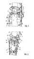
- Fig. 1 in einer perspektivischen Darstellung die Vorrichtung zum Verschieben einer Steigschutzeinrichtung in ihrer Position als Teil eines Steigweges;
- Fig. 2 die Vorrichtung zum Verschieben einer Steigschutzeinrichtung in einer Stellung ausserhalb eines Steigweges;
- Fig. 3 die Vorrichtung zum Verschieben einer Steigschutzeinrichtung im Vertikalschnitt und
- Fig. 4 den Schlitten aus Fig. 1 in Vergrößerung.
- Wie die Figuren 1 und 2 zeigen, sind an einem Betonmast 10 ein erster Steigweg 4 und ein zweiter Steigweg 5 in Form von Leitern mit einem Mittelholm 11 und Leitersprossen 12 befestigt, wie sie aus der DE-PS 1 961 757 bekannt sind. Der erste Steigweg 4 führt vom Erdboden bis zu der in den Figuren 1 und 2 gezeigten Stelle, während der zweite Steigweg 5 von der in den Figuren 1 und 2 gezeigten Stelle nach oben weiterführt. Beide Steigwege überlappen dabei etwa um 2 m. Die Vorrichtung zum Verschieben der Steigschutzeinrichtung weist zwei gekrümmte, vertikal übereinander angeordnete und mit Stegen verbundene Rundeisen 6 auf, die als Schienen zur Führung eines Schlittens 13 dienen. Die Rundeisen 6 sind konzentrisch um den Betonmast 10 angeordnet und sind durch Rohrschellen 14 an diesem befestigt. Die Rundeisen 6 sind durch verstellbare Abstandschrauben 15 in ihrem Abstand von dem Betonmast einjustierbar.
- Die beiden Rundeisen 6 führen einen Schlitten 13 (Fig. 4) vom Ende des ersten Steigweges 4 zu einer Lücke des zweiten Steigwegs 5, der in dem vorliegendem Ausführungsbeispiel um 1800 versetzt an dem Betonmast angeordnet ist. Der Schlitten 13 (Fig. 3) wird durch insgesamt 8 Rollen 16 auf den beiden Rundeisen 6 geführt. Der Schlitten 13 ist ein U-Profileisen ausreichender Länge, so dass von den beiden Schenkeln des U-Profileisens insgesamt acht Rollen 16 nach innen abstehend angeordnet werden können, wobei jeweils zwei Rollen 16 zusammen die Rundeisen 6 umklammern. Zur sicheren Führung wird jedes Rundeisen 6 von zwei Rollenpaaren umklammert, die in einem Abstand von etwa 20 cm angeordnet sind. Der Schlitten 13 trägt ein kleines Teilstück 1 des Mittelholms der Leiter, und der Abstand der Rundeisen 6 vom Betonmast 10 ist so eingestellt, dass das Teilstück 1 mittels des Schlittens 13 in exakte Fluchtung mit den Mittelholmen 11 des ersten bzw. zweiten Steigweges 4, 5 gebracht werden kann.
- Wie in der DE-PS 1 961 757 näher beschrieben ist, dient der Mittelholm 11 zugleich als Längsführung für einen Schieber 8 einer Steigschutzeinrichtung. Die die Leiter hochsteigende Person ist mittels eines Sicherheitsgürtels an diesem Schieber 8 gesichert. Der Schieber 8 weist als Arretierung eine Sperrklinke auf, die durch Federwirkung in ihrer Sperrstellung gehalten wird, in der die Klinkennase in das Innere des U-Profils der Längsführung ragt und gegen dort befindliche Anschlagflächen anliegt. Als Anschlagflächen dienen dabei die Oberseiten der Leitersprossen 12, die durch paarweise fluchtende Öffnungen verlaufen, die durch die parallelen Seitenwände des U-Profils des Mittelholms 11 angeordnet sind. Zusätzlich zu den Leitersprossen 12 können weitere Anschlagflächen vorgesehen werden, indem rechteckige Hohlprofilstücke 17 durch weitere öffnungen in den Seitenwänden des U-Profils des Mittelholms 11 eingesetzt sind. Das Teilstück 1 ist fest an dem Schlitten 13 angeschraubt und enthält in seinem Inneren eine Anschlagfläche, die durch ein solches zusätzliches Hohlprofilstück 17 gebildet wird, so dass der Schieber 8 in dem Teilstück 1 arretiert ist. Um ein unbeabsichtigtes Herausfallen des Schiebers 8 aus dem Teilstück l zusätzlich zu verhindern, sind am oberen und unteren Ende des Teilstücks 1 Arretierungsbolzen 18 vorgesehen, die durch eine Feder radial nach aussen, d. h. zu der den.Steigweg erklimmenden Person gedrückt werden und von Hand zurückgedrückt werden, wenn der Schlitten über das untere oder obere Ende des Teilstückes 1 verschoben werden soll.
- In einem Abstand von etwa 1,5 m unterhalb der Rundeisen 6 und in einem Abstand von etwa 30 cm darüber sind noch ein unterer Steigring 19 und ein oberer Steigring 20 durch Rohrschellen an dem Betonmast 10 befestigt. Der untere Steigring 19 wird beim Umsteigen betreten und der obere Steigring 20 dient dabei zum Festhalten.
- Die Benutzung der Vorrichtung zum Verschieben der Steigschutzeinrichtung erfolgt beim Aufwärtsklettern in der Weise, dass die Person, wenn sie am oberen Ende des ersten Steigweges 4 ankommt, den Schlitten 13 in die in Fig. 1 und 2 linke Position bringt, in der das Teilstück 1 genau an das obere Ende des Mittelholms 11 des ersten Steigweges 4 anschliesst. Die Person verschiebt dann den Schieber 8 der Steigschutzvorrichtung von dem Mittelholm 11 in das Teilstück 1, wozu noch der Arretierungsbolzen 18 am unteren Ende des Teilstücks 1 zurückgedrückt wird. Die Sperrklinke des Schiebers liegt dabei gegen die durch das Hohlprofilstück 17 des Teilstücks 1 gebildete Anschlagfläche an, so dass volle Sicherheit gegeben ist. Die Person verlässt dann den ersten Steigweg 4 und tritt auf den unteren Steigring 19 und hält sich dabei gleichzeitig am oberen Steigring 20 fest und betritt von dort den zweiten Steigweg 2, der von etwas unterhalb dem unteren Steigring 19 nach oben führt. Beide Steigwege 4, 5 überlappen sich etwa um 2 m. Der Schlitten 13 wird beim Umsteigen vom ersten Steigweg 4 auf den zweiten Steigweg 5 automatisch mitgezogen und rollt auf den beiden parallel gekrümmten Rundeisen 6 zu dem zweiten Steigweg hinüber, so dass die Person immer mit dem gleichen Schieber 8 gesichert vom einen Steigweg 4 zum anderen Steigweg 5 hinüberwechseln kann. Der obere Arretierungsbolzen 18 sorgt dabei dafür, dass der Schieber 8 unterwegs auch nicht nach oben aus dem Teilstück 1 herausrutschen kann.
- Auf dem zweiten, nach oben führenden Steigweg 5 angekommen, sorgt ein Anschlag 21 am oberen Ende des Teilstückes 1 dafür,-dass sich das Teilstück 1 genau in die Lücke dieses Steigwegs 5 einfügt. Nach Eindrücken des oberen Arretierungsbolzens 18 kann die Person nun auf dem zweiten Steigweg 5 weiter nach oben klettern, wobei der Schieber 8 mitgezogen wird.
- Beim Herunterklettern erfolgen die einzelnen Massnahmen in umgekehrter Reihenfolge, wobei nunmehr ein weiterer Anschlag 22, der am oberen Ende des Mittelholms 11 des ersten Steigweges 4 vorspringt, den Schlitten 13 anhält und justiert, so dass der Schieber 8 nach unten in den Mittelholm 11 des unteren Steigweges 4 gleiten kann.
Claims (4)
dass das Teilstück (1) an seinem oberen und unteren .Ende eine lösbare Sicherung gegen ein Herausfallen des Schiebers (8) aufweist.
Priority Applications (1)
| Application Number | Priority Date | Filing Date | Title |
|---|---|---|---|
| AT84106987T ATE31101T1 (de) | 1983-06-21 | 1984-06-19 | Vorrichtung zum verschieben einer steigschutzeinrichtung von einem ersten steigweg zu einem zweiten steigweg. |
Applications Claiming Priority (2)
| Application Number | Priority Date | Filing Date | Title |
|---|---|---|---|
| DE3322298A DE3322298C1 (de) | 1983-06-21 | 1983-06-21 | Vorrichtung zum Verschieben einer Steigschutzeinrichtung von einem ersten Steigweg zu einem zweiten Steigweg |
| DE3322298 | 1983-06-21 |
Publications (3)
| Publication Number | Publication Date |
|---|---|
| EP0129241A2 true EP0129241A2 (de) | 1984-12-27 |
| EP0129241A3 EP0129241A3 (en) | 1986-01-22 |
| EP0129241B1 EP0129241B1 (de) | 1987-11-25 |
Family
ID=6201978
Family Applications (1)
| Application Number | Title | Priority Date | Filing Date |
|---|---|---|---|
| EP84106987A Expired EP0129241B1 (de) | 1983-06-21 | 1984-06-19 | Vorrichtung zum Verschieben einer Steigschutzeinrichtung von einem ersten Steigweg zu einem zweiten Steigweg |
Country Status (7)
| Country | Link |
|---|---|
| EP (1) | EP0129241B1 (de) |
| AT (1) | ATE31101T1 (de) |
| DE (2) | DE3322298C1 (de) |
| DK (1) | DK298484A (de) |
| ES (1) | ES288746Y (de) |
| NO (1) | NO842452L (de) |
| ZA (1) | ZA844670B (de) |
Cited By (3)
| Publication number | Priority date | Publication date | Assignee | Title |
|---|---|---|---|---|
| DE29719485U1 (de) * | 1997-11-03 | 1999-03-18 | Soell Gmbh | Absturzsicherung |
| WO2000012176A1 (de) | 1998-08-28 | 2000-03-09 | Söll Gmbh | Vorrichtung zum wechseln der führungsebene eines läufers, der auf der führungsschiene einer absturzsicherung geführt ist |
| EP1222944A1 (de) * | 2001-01-11 | 2002-07-17 | Sala Group Pty Limited | Verankerungsvervahren und -vorrichtung für Rettungsseil |
Families Citing this family (2)
| Publication number | Priority date | Publication date | Assignee | Title |
|---|---|---|---|---|
| DE8809386U1 (de) * | 1988-07-22 | 1988-12-15 | Soell Industrieschmiede Gmbh, 8670 Hof, De | |
| DE29712753U1 (de) * | 1997-07-18 | 1997-09-11 | Soell Gmbh | Versenkbare Verlängerung der Führungsschiene einer Steigschutzvorrichtung |
Citations (3)
| Publication number | Priority date | Publication date | Assignee | Title |
|---|---|---|---|---|
| US3348632A (en) * | 1965-02-16 | 1967-10-24 | William E Swager | Climbing device |
| DE2060718A1 (de) * | 1970-12-10 | 1972-06-22 | Fahrleitungsbau Gmbh | Absturzsicherung fuer Leitern oder aehnliche Vorrichtungen |
| FR2495684A1 (fr) * | 1980-12-09 | 1982-06-11 | Risacher Marcel Charles | Protecteur coulissant et amovible pour echelles de moyenne et grande hauteur a un ou plusieurs elements |
Family Cites Families (1)
| Publication number | Priority date | Publication date | Assignee | Title |
|---|---|---|---|---|
| DE1961757C3 (de) * | 1969-12-09 | 1974-04-04 | Karl Soell, Gesenkschmiede, 8670 Hof | Leiter mit Steigschutzvorrichtung |
-
1983
- 1983-06-21 DE DE3322298A patent/DE3322298C1/de not_active Expired
-
1984
- 1984-06-19 NO NO842452A patent/NO842452L/no unknown
- 1984-06-19 EP EP84106987A patent/EP0129241B1/de not_active Expired
- 1984-06-19 DK DK298484A patent/DK298484A/da not_active Application Discontinuation
- 1984-06-19 AT AT84106987T patent/ATE31101T1/de not_active IP Right Cessation
- 1984-06-19 ES ES1984288746U patent/ES288746Y/es not_active Expired
- 1984-06-19 DE DE8484106987T patent/DE3467790D1/de not_active Expired
- 1984-06-20 ZA ZA844670A patent/ZA844670B/xx unknown
Patent Citations (3)
| Publication number | Priority date | Publication date | Assignee | Title |
|---|---|---|---|---|
| US3348632A (en) * | 1965-02-16 | 1967-10-24 | William E Swager | Climbing device |
| DE2060718A1 (de) * | 1970-12-10 | 1972-06-22 | Fahrleitungsbau Gmbh | Absturzsicherung fuer Leitern oder aehnliche Vorrichtungen |
| FR2495684A1 (fr) * | 1980-12-09 | 1982-06-11 | Risacher Marcel Charles | Protecteur coulissant et amovible pour echelles de moyenne et grande hauteur a un ou plusieurs elements |
Non-Patent Citations (1)
| Title |
|---|
| FABA-KLIMBEVEILIGING, Prospekt St 7610, Seiten 1-8, J.A. Beele, Handelsmaatschappij BV, Hoorn, NL; * |
Cited By (8)
| Publication number | Priority date | Publication date | Assignee | Title |
|---|---|---|---|---|
| DE29719485U1 (de) * | 1997-11-03 | 1999-03-18 | Soell Gmbh | Absturzsicherung |
| WO1999022816A2 (de) | 1997-11-03 | 1999-05-14 | Söll Gmbh | Absturzsicherung |
| US6571912B2 (en) | 1997-11-03 | 2003-06-03 | Christian Dalloz Holding Deutschland Gmbh & Co. Kg | Falling safeguard device |
| WO2000012176A1 (de) | 1998-08-28 | 2000-03-09 | Söll Gmbh | Vorrichtung zum wechseln der führungsebene eines läufers, der auf der führungsschiene einer absturzsicherung geführt ist |
| EP1222944A1 (de) * | 2001-01-11 | 2002-07-17 | Sala Group Pty Limited | Verankerungsvervahren und -vorrichtung für Rettungsseil |
| US6604605B2 (en) | 2001-01-11 | 2003-08-12 | Sala Group Pty Limited | Safety line anchorage methods and apparatus |
| US6736239B2 (en) | 2001-01-11 | 2004-05-18 | Sala Group Pty Limited | Safety line anchorage methods and apparatus |
| US6802390B2 (en) | 2001-01-11 | 2004-10-12 | Capital Safety Group (Australia) Pty Limited | Safety line anchorage methods and apparatus |
Also Published As
| Publication number | Publication date |
|---|---|
| DE3322298C1 (de) | 1984-07-19 |
| DE3467790D1 (en) | 1988-01-07 |
| DK298484D0 (da) | 1984-06-19 |
| EP0129241A3 (en) | 1986-01-22 |
| ES288746U (es) | 1986-01-16 |
| ZA844670B (en) | 1985-08-28 |
| ES288746Y (es) | 1986-10-01 |
| EP0129241B1 (de) | 1987-11-25 |
| ATE31101T1 (de) | 1987-12-15 |
| NO842452L (no) | 1984-12-27 |
| DK298484A (da) | 1984-12-22 |
Similar Documents
| Publication | Publication Date | Title |
|---|---|---|
| EP0076974B1 (de) | Plattform zum Heben von Personen | |
| DE19723000C2 (de) | Abstützung für Anlegeleitern | |
| DE2400313A1 (de) | Hilfseinrichtung fuer einen seilnetzkuehlturm | |
| EP0457171B1 (de) | Einrichtung an einer Schalung zur Errichtung eines Mauerwerkes | |
| DE3728282A1 (de) | Absturzsicherungsvorrichtung, insbesondere fuer dacharbeiten | |
| EP0129241B1 (de) | Vorrichtung zum Verschieben einer Steigschutzeinrichtung von einem ersten Steigweg zu einem zweiten Steigweg | |
| CH631943A5 (en) | Apparatus for travelling on a perpendicular or virtually perpendicular wall | |
| EP0341563A2 (de) | Aus mehreren Teleskopschüssen gebildeter Schrägaufzug | |
| EP0996805B1 (de) | Versenkbare verlängerung der führungsschiene einer steigschutzvorrichtung | |
| DE102008050178A1 (de) | Arbeitsgerüst | |
| DE3816320C1 (de) | ||
| DE4219732C2 (de) | Montagegerüst | |
| DE2932707A1 (de) | Steigvorrichtung fuer ein bauwerk, insbesondere fuer einen mast, z.b. hochspannungsleitungsmast | |
| DE3433281A1 (de) | Einstiegsleiter fuer einen versorgungsschacht | |
| DE3026443C2 (de) | Mit einem Holm einer Gerüstleiter verbindbarer Leiterunterbau | |
| EP0428090B1 (de) | Sicherungsvorrichtung | |
| DE3403959A1 (de) | Wehr mit dammbalkenfuehrungen und hebe- und absenkvorrichtung | |
| DE2337892C2 (de) | Arbeitsgerüst mit heb- und senkbarer Arbeitsbühne | |
| DE102008016601B3 (de) | Absturzsicherung | |
| DE2643982B2 (de) | Zugangsvorrichtung zu einer Arbeitsbühne eines Gerüsts | |
| DD289747A5 (de) | Auslegerrollbuehne fuer bauaufzuege | |
| DE3040707C2 (de) | ||
| DE2915607A1 (de) | Sicherungs- und rettungsgestell | |
| DE1082725B (de) | Mittels Klettergeraeten an Kletterstangen hebbare Gleitschalung zur Herstellung von Betonbauwerken mit ein- oder beidseitig gleichbleibend geneigten und geraden oder gekruemmten Waenden | |
| EP0179480A2 (de) | Traggestell für ein Gerüst zur Uberbrückung eines Gangbodens oder dergleichen |
Legal Events
| Date | Code | Title | Description |
|---|---|---|---|
| PUAI | Public reference made under article 153(3) epc to a published international application that has entered the european phase |
Free format text: ORIGINAL CODE: 0009012 |
|
| AK | Designated contracting states |
Designated state(s): AT BE CH DE FR GB IT LI LU NL SE |
|
| PUAL | Search report despatched |
Free format text: ORIGINAL CODE: 0009013 |
|
| AK | Designated contracting states |
Designated state(s): AT BE CH DE FR GB IT LI LU NL SE |
|
| 17P | Request for examination filed |
Effective date: 19860721 |
|
| 17Q | First examination report despatched |
Effective date: 19870218 |
|
| ITF | It: translation for a ep patent filed |
Owner name: MARCHI & MITTLER S.R.L. |
|
| GRAA | (expected) grant |
Free format text: ORIGINAL CODE: 0009210 |
|
| RAP1 | Party data changed (applicant data changed or rights of an application transferred) |
Owner name: SOELL INDUSTRIESCHMIEDE GMBH |
|
| AK | Designated contracting states |
Kind code of ref document: B1 Designated state(s): AT BE CH DE FR GB IT LI LU NL SE |
|
| PG25 | Lapsed in a contracting state [announced via postgrant information from national office to epo] |
Ref country code: NL Effective date: 19871125 Ref country code: BE Effective date: 19871125 |
|
| REF | Corresponds to: |
Ref document number: 31101 Country of ref document: AT Date of ref document: 19871215 Kind code of ref document: T |
|
| PG25 | Lapsed in a contracting state [announced via postgrant information from national office to epo] |
Ref country code: SE Effective date: 19871130 |
|
| REF | Corresponds to: |
Ref document number: 3467790 Country of ref document: DE Date of ref document: 19880107 |
|
| ET | Fr: translation filed | ||
| GBT | Gb: translation of ep patent filed (gb section 77(6)(a)/1977) | ||
| NLV1 | Nl: lapsed or annulled due to failure to fulfill the requirements of art. 29p and 29m of the patents act | ||
| PG25 | Lapsed in a contracting state [announced via postgrant information from national office to epo] |
Ref country code: AT Effective date: 19880619 |
|
| PG25 | Lapsed in a contracting state [announced via postgrant information from national office to epo] |
Ref country code: LU Free format text: LAPSE BECAUSE OF NON-PAYMENT OF DUE FEES Effective date: 19880630 |
|
| PLBE | No opposition filed within time limit |
Free format text: ORIGINAL CODE: 0009261 |
|
| STAA | Information on the status of an ep patent application or granted ep patent |
Free format text: STATUS: NO OPPOSITION FILED WITHIN TIME LIMIT |
|
| 26N | No opposition filed | ||
| ITTA | It: last paid annual fee | ||
| PGFP | Annual fee paid to national office [announced via postgrant information from national office to epo] |
Ref country code: FR Payment date: 20010529 Year of fee payment: 18 |
|
| PGFP | Annual fee paid to national office [announced via postgrant information from national office to epo] |
Ref country code: GB Payment date: 20010613 Year of fee payment: 18 |
|
| PGFP | Annual fee paid to national office [announced via postgrant information from national office to epo] |
Ref country code: DE Payment date: 20010627 Year of fee payment: 18 |
|
| PGFP | Annual fee paid to national office [announced via postgrant information from national office to epo] |
Ref country code: CH Payment date: 20010629 Year of fee payment: 18 |
|
| REG | Reference to a national code |
Ref country code: GB Ref legal event code: IF02 |
|
| PG25 | Lapsed in a contracting state [announced via postgrant information from national office to epo] |
Ref country code: GB Free format text: LAPSE BECAUSE OF NON-PAYMENT OF DUE FEES Effective date: 20020619 |
|
| PG25 | Lapsed in a contracting state [announced via postgrant information from national office to epo] |
Ref country code: LI Free format text: LAPSE BECAUSE OF NON-PAYMENT OF DUE FEES Effective date: 20020630 Ref country code: CH Free format text: LAPSE BECAUSE OF NON-PAYMENT OF DUE FEES Effective date: 20020630 |
|
| PG25 | Lapsed in a contracting state [announced via postgrant information from national office to epo] |
Ref country code: DE Free format text: LAPSE BECAUSE OF NON-PAYMENT OF DUE FEES Effective date: 20030101 |
|
| GBPC | Gb: european patent ceased through non-payment of renewal fee |
Effective date: 20020619 |
|
| REG | Reference to a national code |
Ref country code: CH Ref legal event code: PL |
|
| PG25 | Lapsed in a contracting state [announced via postgrant information from national office to epo] |
Ref country code: FR Free format text: LAPSE BECAUSE OF NON-PAYMENT OF DUE FEES Effective date: 20030228 |
|
| REG | Reference to a national code |
Ref country code: FR Ref legal event code: ST |