EP0129092B1 - Numerisch gesteuertes Gerät zur Anwendung mit einem Werkzeug - Google Patents
Numerisch gesteuertes Gerät zur Anwendung mit einem Werkzeug Download PDFInfo
- Publication number
- EP0129092B1 EP0129092B1 EP84105877A EP84105877A EP0129092B1 EP 0129092 B1 EP0129092 B1 EP 0129092B1 EP 84105877 A EP84105877 A EP 84105877A EP 84105877 A EP84105877 A EP 84105877A EP 0129092 B1 EP0129092 B1 EP 0129092B1
- Authority
- EP
- European Patent Office
- Prior art keywords
- workpiece
- holder
- numerical control
- control device
- dimensional details
- Prior art date
- Legal status (The legal status is an assumption and is not a legal conclusion. Google has not performed a legal analysis and makes no representation as to the accuracy of the status listed.)
- Expired - Lifetime
Links
Images


Classifications
-
- G—PHYSICS
- G05—CONTROLLING; REGULATING
- G05B—CONTROL OR REGULATING SYSTEMS IN GENERAL; FUNCTIONAL ELEMENTS OF SUCH SYSTEMS; MONITORING OR TESTING ARRANGEMENTS FOR SUCH SYSTEMS OR ELEMENTS
- G05B19/00—Programme-control systems
- G05B19/02—Programme-control systems electric
- G05B19/18—Numerical control [NC], i.e. automatically operating machines, in particular machine tools, e.g. in a manufacturing environment, so as to execute positioning, movement or co-ordinated operations by means of programme data in numerical form
- G05B19/4093—Numerical control [NC], i.e. automatically operating machines, in particular machine tools, e.g. in a manufacturing environment, so as to execute positioning, movement or co-ordinated operations by means of programme data in numerical form characterised by part programming, e.g. entry of geometrical information as taken from a technical drawing, combining this with machining and material information to obtain control information, named part programme, for the NC machine
- G05B19/40931—Numerical control [NC], i.e. automatically operating machines, in particular machine tools, e.g. in a manufacturing environment, so as to execute positioning, movement or co-ordinated operations by means of programme data in numerical form characterised by part programming, e.g. entry of geometrical information as taken from a technical drawing, combining this with machining and material information to obtain control information, named part programme, for the NC machine concerning programming of geometry
- G05B19/40932—Shape input
-
- G—PHYSICS
- G05—CONTROLLING; REGULATING
- G05B—CONTROL OR REGULATING SYSTEMS IN GENERAL; FUNCTIONAL ELEMENTS OF SUCH SYSTEMS; MONITORING OR TESTING ARRANGEMENTS FOR SUCH SYSTEMS OR ELEMENTS
- G05B2219/00—Program-control systems
- G05B2219/30—Nc systems
- G05B2219/35—Nc in input of data, input till input file format
- G05B2219/35314—Display workpiece and machine, chuck, jig, clamp, tool
-
- G—PHYSICS
- G05—CONTROLLING; REGULATING
- G05B—CONTROL OR REGULATING SYSTEMS IN GENERAL; FUNCTIONAL ELEMENTS OF SUCH SYSTEMS; MONITORING OR TESTING ARRANGEMENTS FOR SUCH SYSTEMS OR ELEMENTS
- G05B2219/00—Program-control systems
- G05B2219/30—Nc systems
- G05B2219/45—Nc applications
- G05B2219/45136—Turning, lathe
-
- Y—GENERAL TAGGING OF NEW TECHNOLOGICAL DEVELOPMENTS; GENERAL TAGGING OF CROSS-SECTIONAL TECHNOLOGIES SPANNING OVER SEVERAL SECTIONS OF THE IPC; TECHNICAL SUBJECTS COVERED BY FORMER USPC CROSS-REFERENCE ART COLLECTIONS [XRACs] AND DIGESTS
- Y02—TECHNOLOGIES OR APPLICATIONS FOR MITIGATION OR ADAPTATION AGAINST CLIMATE CHANGE
- Y02P—CLIMATE CHANGE MITIGATION TECHNOLOGIES IN THE PRODUCTION OR PROCESSING OF GOODS
- Y02P90/00—Enabling technologies with a potential contribution to greenhouse gas [GHG] emissions mitigation
- Y02P90/02—Total factory control, e.g. smart factories, flexible manufacturing systems [FMS] or integrated manufacturing systems [IMS]
-
- Y—GENERAL TAGGING OF NEW TECHNOLOGICAL DEVELOPMENTS; GENERAL TAGGING OF CROSS-SECTIONAL TECHNOLOGIES SPANNING OVER SEVERAL SECTIONS OF THE IPC; TECHNICAL SUBJECTS COVERED BY FORMER USPC CROSS-REFERENCE ART COLLECTIONS [XRACs] AND DIGESTS
- Y10—TECHNICAL SUBJECTS COVERED BY FORMER USPC
- Y10T—TECHNICAL SUBJECTS COVERED BY FORMER US CLASSIFICATION
- Y10T82/00—Turning
- Y10T82/25—Lathe
- Y10T82/2502—Lathe with program control
Definitions
- the present invention relates to a numerical control device (hereinafer referred to as an "NC device") for use with a machine tool, for example, and more particularly to an NC device including a graphic display unit.
- NC device numerical control device
- NC machining devices machine a workpiece by specifying the position of a tool with respect to the workpiece in the form of corresponding numerical information.
- the NC machining device can machine workpieces of complex configuration with ease and high accuracy at a high production rate.
- FIG. 1 of the accompanying drawings schematically shows a general machine tool controlled by a conventional NC device, the machine tool being a lathe by way of illustrative example.
- a cylindrical workpiece 11 fixedly clamped by a chuck 10 rotatable about a Z-axis has one end supported by a tip 12a of a tailstock 12.
- a cutting tool 14 is secured to a turret or tool base 13.
- the turret 13 is moved in the direction of the arrow Z to cause the cutting tool 14 to cut the workpiece 11.
- the NC device includes a graphic display unit
- the shape of the workpiece 11, a cutting path of the tool 14, and a finished shape of the workpiece 11 are displayed on the display unit for checking the machining program for possible interference between the workpiece and the tool and monitoring the cutting condition.
- the machining program is checked by displaying the tool path as indicated by dotted lines as shown, for example, in Fig. 2 of the accompanying drawings. Whether the workpiece and the tool interfere with each other or not is checked by the determined values of functions which express the shape and position of holder mechanisms composed of the chuck tailstock. It has been generally proposed in "Computer Verification of machine Control Data" by L. O.
- a numerical control device including:
- holder mechanisms such as indicated by reference numerals 10, 12 in Fig. 1 are displayed.
- reference numerals 10, 12 in Fig. 1 A specific embodiment of the present invention will hereinafter be described.
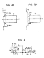
- Figs. 3A and 3B are illustrated of graphic patterns such as that of a lathe to be applied to a graphic display unit.
- a first holder mechanism is composed of a chuck 10 and chuck jaws 10a for holding a workpiece 11.
- the chuck 10 is displayed as fixed in position, there is an instance where the workpiece 11 cannot be held by the chuck 10 as shown in Fig. 3A since the workpiece 11 may not be constant in shape and size.
- the graphic pattern is converted so that the chuck jaws 10a will be moved so as to be able to hold the workpiece 11.
- Fig. 3B illustrates the graphic pattern as thus converted.
- a second holder mechanism is composed of a tailstock 12 having a tip 12a as shown in Figs. 10A and 10B.
- Fig. 4 shows dimensional details of the first and second holder mechanisms. Denoted in Fig. 4 at X 1 ⁇ X 8 are dimensional details of the first holder mechanism, and Y 1 ⁇ Y 2 dimensional details of the second holder mechanism.
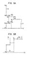
- Data items to be displayed as graphic patterns are all expressed as coordinate data items as shown in Figs. 5A and 5B.
- the relative coordinates are used for the reason that, with such relative coordinates, if a reference point is positionally changed, then all points in a certain coordinate system having such a reference point as a reference will be renewed, but with all points expressed only by absolute coordinates, if a positional change were to be made, the extent of such a positional change would have to be computed for all points in the absolute coordinate system.
- Reference coordinates will be simply described.
- Reference coordinates means having an origin of a local coordinate sysem as shown in Fig. 6.
- the reference coordinates are indicative of a single coordinate set or value when viewed from an outer coordinate system.
- Figs. 7A and 7B show a relative coordinate system having the reference point p 1 as the origin.
- the reference coordinates p 1 , q 1 of the chuck 10 and the chuck jaw 10a as shown in Figs. 5A and 5B can be be determined by an algorithm illustrated in Fig. 8.
- the algorithm of Fig. 8 is executed by a system shown in Fig. 9 whch operates as follows:
- Data items indicative of the shape of the holder mechanism and on the diameter of the workpiece are entered through an input unit of the NC device and stored in a memory. Based on these data items, a CPU computes the position of a chuck jaw, generates a pattern corresponding to the shape thereof, and displays the same on a display unit.
- the flowchart of Fig. 8 is composed of successive steps 1 through 5.
- a workpiece shape and a chuck shape are entered as coordinate data items in step 1. Coordinates on the outside diameter of the workpiece shape at the chuck are established as a reference point for the chuck jaw in the step 2.
- a point on the central axis which is spaced a distance Z, (Fig. 5B) from the end of the workpiece which faces the chuck is regarded as a reference point for the chuck in step 3.
- Actual coordinates can be determined by adding relative coordinates to the reference points thus defined in step 4.
- a chuck shape converted through linear interpolation of the actual coordinates is completely displayed together with the actual machining condition in step 5.
- Figs. 10A and 10B are illustrative of the display of the tailstock 12 or the second holder mechanism.
- Reference coordinates r 1 (Fig. 10A) can be established as shown in Fig. 10B by setting a workpiece end surface S on the Z-axis and setting X at "0" (on the Z-axis). The following process is the same as described with respect to the chuck 10, i.e., the shape of the tailstock is defined by a local coordinate system, and the tip of the tailstock is given by reference coordinates, which are translated and displayed.
- NC device has been described as being used with a lathe, the present invention is applicable to NC devices used in combination with various other machine tools such as a machining center.
Landscapes
- Physics & Mathematics (AREA)
- Engineering & Computer Science (AREA)
- Geometry (AREA)
- Human Computer Interaction (AREA)
- Manufacturing & Machinery (AREA)
- General Physics & Mathematics (AREA)
- Automation & Control Theory (AREA)
- Numerical Control (AREA)
Claims (4)
Applications Claiming Priority (2)
| Application Number | Priority Date | Filing Date | Title |
|---|---|---|---|
| JP58090273A JPS59229615A (ja) | 1983-05-23 | 1983-05-23 | 数値制御装置 |
| JP90273/83 | 1983-05-23 |
Publications (4)
| Publication Number | Publication Date |
|---|---|
| EP0129092A2 EP0129092A2 (de) | 1984-12-27 |
| EP0129092A3 EP0129092A3 (en) | 1986-04-16 |
| EP0129092B1 true EP0129092B1 (de) | 1990-04-11 |
| EP0129092B2 EP0129092B2 (de) | 1997-04-09 |
Family
ID=13993901
Family Applications (1)
| Application Number | Title | Priority Date | Filing Date |
|---|---|---|---|
| EP84105877A Expired - Lifetime EP0129092B2 (de) | 1983-05-23 | 1984-05-23 | Numerisch gesteuertes Gerät zur Anwendung mit einem Werkzeug |
Country Status (4)
| Country | Link |
|---|---|
| US (1) | US4633409A (de) |
| EP (1) | EP0129092B2 (de) |
| JP (1) | JPS59229615A (de) |
| DE (1) | DE3481942D1 (de) |
Families Citing this family (22)
| Publication number | Priority date | Publication date | Assignee | Title |
|---|---|---|---|---|
| DE3403677A1 (de) * | 1984-02-03 | 1985-08-08 | Dr. Johannes Heidenhain Gmbh, 8225 Traunreut | Verfahren zum erzeugen von werkstueckkonturen |
| JPS60167738A (ja) * | 1984-02-06 | 1985-08-31 | Fanuc Ltd | 自動工具交換装置の工具表示方式 |
| DE3446138A1 (de) * | 1984-12-18 | 1986-06-19 | Fortuna-Werke Maschinenfabrik Gmbh, 7000 Stuttgart | Verfahren zur bestimmung der position eines werkstueckes in einer nc-gesteuerten maschine sowie eine nc-gesteuerte maschine zur durchfuehrung eines solchen verfahrens |
| JPS61184610A (ja) * | 1985-02-12 | 1986-08-18 | Fanuc Ltd | 移動軌跡描画方式 |
| JPS61244444A (ja) * | 1985-04-19 | 1986-10-30 | Hitachi Seiki Co Ltd | 工作機械のワ−ク座標系設定装置 |
| JPS62199338A (ja) * | 1986-02-27 | 1987-09-03 | Fanuc Ltd | 工具衝突自動防止方法 |
| JPS645779A (en) * | 1987-06-29 | 1989-01-10 | Fanuc Ltd | Robot arrangement examination system |
| US4912625A (en) * | 1987-09-30 | 1990-03-27 | The Boeing Company | Graphics verification system for numerical control programs |
| JPH07107647B2 (ja) * | 1988-02-12 | 1995-11-15 | 三菱電機株式会社 | 複数系統制御の干渉チェック方法 |
| JP2935706B2 (ja) * | 1988-12-07 | 1999-08-16 | ファナック株式会社 | 加工プログラム修正方法 |
| US5122966A (en) * | 1989-09-18 | 1992-06-16 | Northern Research & Engineering | Computer generated tool path interference check method |
| JPH0773818B2 (ja) * | 1989-11-17 | 1995-08-09 | オークマ株式会社 | 旋削加工における加工範囲自動決定方法及び旋盤用自動プログラミングシステム |
| US5293106A (en) * | 1989-12-11 | 1994-03-08 | Murata Kikai Kabushiki Kaisha | Program reviewing device in numerical control processing apparatus |
| JPH03196310A (ja) * | 1989-12-26 | 1991-08-27 | Fanuc Ltd | 数値制御装置の表示方式 |
| JP3650027B2 (ja) * | 1998-08-24 | 2005-05-18 | オークマ株式会社 | Nc加工支援方法及び装置 |
| JP3537362B2 (ja) | 1999-10-12 | 2004-06-14 | ファナック株式会社 | ロボットシステム用グラフィック表示装置 |
| US6985793B2 (en) * | 2003-01-31 | 2006-01-10 | Delphi Technologies, Inc. | Horizontally structured CAD/CAM coordinate system for manufacturing design |
| US20040153296A1 (en) * | 2003-01-31 | 2004-08-05 | Landers Diane M. | Horizontally structured CAD/CAM coordinate system |
| WO2005003872A1 (ja) * | 2003-07-04 | 2005-01-13 | Mitsubishi Denki Kabushiki Kaisha | 自動プログラミング方法および装置 |
| US7062351B2 (en) * | 2003-09-25 | 2006-06-13 | The Boeing Company | Clamp avoidance cutter path regeneration |
| EP2533116A1 (de) * | 2010-02-05 | 2012-12-12 | Hitachi, Ltd. | Verfahren zur erzeugung eines verarbeitungspfads und vorrichtung dafür |
| JP5059914B2 (ja) * | 2010-07-12 | 2012-10-31 | ファナック株式会社 | 工作機械の減速要因判別手段を備えた工具軌跡表示装置 |
Family Cites Families (9)
| Publication number | Priority date | Publication date | Assignee | Title |
|---|---|---|---|---|
| US4033206A (en) * | 1974-07-11 | 1977-07-05 | Daihatsu Motor Co., Ltd. | Numerically controlled machine tool |
| US4204144A (en) * | 1977-10-13 | 1980-05-20 | Midgitronics Inc. | Position control system |
| GB2054199B (en) * | 1979-06-14 | 1983-10-05 | Daihatsu Motor Co Ltd | Numerically controlled machine tool |
| JPS5719809A (en) * | 1980-07-10 | 1982-02-02 | Fanuc Ltd | Numerical control information generating system |
| US4521860A (en) * | 1981-09-14 | 1985-06-04 | Yamazaki Machinery Works, Ltd. | Methods of entering machining information and display therefor in a numerically controlled machine tool |
| JPS58155101A (ja) * | 1982-03-11 | 1983-09-14 | Yamazaki Mazak Corp | 4軸数値制御旋盤 |
| JPS58163009A (ja) * | 1982-03-23 | 1983-09-27 | Toyoda Mach Works Ltd | 対話式デ−タ入力機能を備えた数値制御装置における加工情報入力方法 |
| JPS58168104A (ja) * | 1982-03-30 | 1983-10-04 | Yamazaki Mazak Corp | 数値制御装置 |
| JPS59158409A (ja) * | 1983-03-01 | 1984-09-07 | Mitsubishi Electric Corp | 数値制御装置 |
-
1983
- 1983-05-23 JP JP58090273A patent/JPS59229615A/ja active Granted
-
1984
- 1984-05-23 EP EP84105877A patent/EP0129092B2/de not_active Expired - Lifetime
- 1984-05-23 DE DE8484105877T patent/DE3481942D1/de not_active Expired - Lifetime
- 1984-05-23 US US06/613,472 patent/US4633409A/en not_active Expired - Lifetime
Also Published As
| Publication number | Publication date |
|---|---|
| JPS59229615A (ja) | 1984-12-24 |
| EP0129092B2 (de) | 1997-04-09 |
| EP0129092A3 (en) | 1986-04-16 |
| US4633409A (en) | 1986-12-30 |
| DE3481942D1 (de) | 1990-05-17 |
| JPH0417443B2 (de) | 1992-03-26 |
| EP0129092A2 (de) | 1984-12-27 |
Similar Documents
| Publication | Publication Date | Title |
|---|---|---|
| EP0129092B1 (de) | Numerisch gesteuertes Gerät zur Anwendung mit einem Werkzeug | |
| EP0129091B1 (de) | Numerisches Steuerungssystem, grafisches Sichtgerät und Werkzeugmaschine | |
| JPH01246046A (ja) | 倣い装置 | |
| CN109648368A (zh) | 一种消除数控加工工作台回转误差的工件坐标系设置方法 | |
| US4639855A (en) | Tool display method for lathe equipped with numerical control unit | |
| EP0620079A4 (en) | Method for checking machining program for numerical controller. | |
| JPH04159058A (ja) | 工具補正量入力機能を有する数値制御装置 | |
| JPS62163109A (ja) | 数値制御装置 | |
| US5654618A (en) | Process for the two-dimensional determination of a work-area contour for lathes | |
| CN110297458B (zh) | 保温杯抛光机加工路径的实现方法 | |
| JPS60180749A (ja) | 数値制御旋盤における加工基準点の補正制御方法 | |
| JPH06246589A (ja) | 機内測定による非円形ワークの誤差補正方法 | |
| JPS60175555U (ja) | Nc工作機械の加工基準点補正装置 | |
| JP2581535B2 (ja) | 工作機械の座標系設定装置 | |
| JP2663931B2 (ja) | 数値制御装置の図形表示方法 | |
| JPH05108134A (ja) | 主軸の割出対応の座標変換方法 | |
| JP3568173B2 (ja) | 数値制御工作機械における座標データ指定形式の切換方法 | |
| JP2002154034A (ja) | 工作機械における工具刃先位置の設定方法 | |
| JPS62154110A (ja) | 数値制御装置の制御方式 | |
| JP2568111B2 (ja) | Nc施盤における干渉防止バリアの作成方法 | |
| Brecher et al. | Numerical Controllers | |
| JPS63306853A (ja) | 数値制御工作機械の刃先座標位置設定装置 | |
| JPH04131910A (ja) | 数値制御旋盤のワーク座標シフト量の設定方法およびその装置 | |
| JPH04131909A (ja) | 数値制御複合旋盤における加工座標系設定方法 | |
| Marchitto | To probe or not to probe |
Legal Events
| Date | Code | Title | Description |
|---|---|---|---|
| PUAI | Public reference made under article 153(3) epc to a published international application that has entered the european phase |
Free format text: ORIGINAL CODE: 0009012 |
|
| AK | Designated contracting states |
Designated state(s): DE FR GB |
|
| PUAL | Search report despatched |
Free format text: ORIGINAL CODE: 0009013 |
|
| AK | Designated contracting states |
Kind code of ref document: A3 Designated state(s): DE FR GB |
|
| 17P | Request for examination filed |
Effective date: 19860512 |
|
| 17Q | First examination report despatched |
Effective date: 19870909 |
|
| GRAA | (expected) grant |
Free format text: ORIGINAL CODE: 0009210 |
|
| AK | Designated contracting states |
Kind code of ref document: B1 Designated state(s): DE FR GB |
|
| REF | Corresponds to: |
Ref document number: 3481942 Country of ref document: DE Date of ref document: 19900517 |
|
| ET | Fr: translation filed | ||
| PLBI | Opposition filed |
Free format text: ORIGINAL CODE: 0009260 |
|
| 26 | Opposition filed |
Opponent name: ROBERT BOSCH GMBH Effective date: 19910109 |
|
| PGFP | Annual fee paid to national office [announced via postgrant information from national office to epo] |
Ref country code: FR Payment date: 19920521 Year of fee payment: 9 |
|
| PG25 | Lapsed in a contracting state [announced via postgrant information from national office to epo] |
Ref country code: FR Effective date: 19940131 |
|
| REG | Reference to a national code |
Ref country code: FR Ref legal event code: ST |
|
| REG | Reference to a national code |
Ref country code: GB Ref legal event code: 746 Effective date: 19950523 |
|
| PLAW | Interlocutory decision in opposition |
Free format text: ORIGINAL CODE: EPIDOS IDOP |
|
| PLAW | Interlocutory decision in opposition |
Free format text: ORIGINAL CODE: EPIDOS IDOP |
|
| PUAH | Patent maintained in amended form |
Free format text: ORIGINAL CODE: 0009272 |
|
| STAA | Information on the status of an ep patent application or granted ep patent |
Free format text: STATUS: PATENT MAINTAINED AS AMENDED |
|
| 27A | Patent maintained in amended form |
Effective date: 19970409 |
|
| AK | Designated contracting states |
Kind code of ref document: B2 Designated state(s): DE FR GB |
|
| EN | Fr: translation not filed | ||
| PGFP | Annual fee paid to national office [announced via postgrant information from national office to epo] |
Ref country code: GB Payment date: 20010523 Year of fee payment: 18 |
|
| REG | Reference to a national code |
Ref country code: GB Ref legal event code: IF02 |
|
| PG25 | Lapsed in a contracting state [announced via postgrant information from national office to epo] |
Ref country code: GB Free format text: LAPSE BECAUSE OF NON-PAYMENT OF DUE FEES Effective date: 20020523 |
|
| GBPC | Gb: european patent ceased through non-payment of renewal fee |
Effective date: 20020523 |
|
| PGFP | Annual fee paid to national office [announced via postgrant information from national office to epo] |
Ref country code: DE Payment date: 20030605 Year of fee payment: 20 |
|
| APAH | Appeal reference modified |
Free format text: ORIGINAL CODE: EPIDOSCREFNO |