EP0124908A2 - Verfahren zur Gewinnung von Rasterpunkt-Prozentwerten für genaue Farbwiedergabe - Google Patents
Verfahren zur Gewinnung von Rasterpunkt-Prozentwerten für genaue Farbwiedergabe Download PDFInfo
- Publication number
- EP0124908A2 EP0124908A2 EP84105255A EP84105255A EP0124908A2 EP 0124908 A2 EP0124908 A2 EP 0124908A2 EP 84105255 A EP84105255 A EP 84105255A EP 84105255 A EP84105255 A EP 84105255A EP 0124908 A2 EP0124908 A2 EP 0124908A2
- Authority
- EP
- European Patent Office
- Prior art keywords
- color
- color information
- tone dot
- specimen
- percent
- Prior art date
- Legal status (The legal status is an assumption and is not a legal conclusion. Google has not performed a legal analysis and makes no representation as to the accuracy of the status listed.)
- Granted
Links
Images


Classifications
-
- G—PHYSICS
- G03—PHOTOGRAPHY; CINEMATOGRAPHY; ANALOGOUS TECHNIQUES USING WAVES OTHER THAN OPTICAL WAVES; ELECTROGRAPHY; HOLOGRAPHY
- G03F—PHOTOMECHANICAL PRODUCTION OF TEXTURED OR PATTERNED SURFACES, e.g. FOR PRINTING, FOR PROCESSING OF SEMICONDUCTOR DEVICES; MATERIALS THEREFOR; ORIGINALS THEREFOR; APPARATUS SPECIALLY ADAPTED THEREFOR
- G03F5/00—Screening processes; Screens therefor
-
- B—PERFORMING OPERATIONS; TRANSPORTING
- B41—PRINTING; LINING MACHINES; TYPEWRITERS; STAMPS
- B41F—PRINTING MACHINES OR PRESSES
- B41F33/00—Indicating, counting, warning, control or safety devices
- B41F33/0027—Devices for scanning originals, printing formes or the like for determining or presetting the ink supply
Definitions
- This invention relates to a method of obtaining half-tone dot percents of color separations of C (cyan), M (magenta), Y (yellow) and Bk (black) for carrying out printing in accordance with color information obtained by optically measuring a color specimen.
- a small sheet of paper for assigning colors called as a color specimen has been sometimes attached to a layout.
- a small sheet of paper painted with color of said background is attached as a color specimen and is sent to a printing factory.
- the printing factory employs a four-color printing system using color separations of C, M, Y and Bk, which is the commonest multicolor printing system, and decides what percent of half-tone dot percents of color separations of C, M, Y and Bk should be used to print the assigned portion with the same color as that of the color specimen, before preparation of color separations under such conditions and printing.
- the above-described work includes preparing a color chart which is an assembly of a multiplicity of printed matters, said color chart being printed with half-tone dot percents of color separations of C, M, Y, and Bk varied at intervals of about 10%, visually comparing the color specimen with colors on the color chart by an operator to select a color most approximate to the color specimen out of the color chart, utilizing the fact that half-tone dot percents of color separations necessary for printing colors in the color chart are described in the color chart to find half-tone dot percents of color separations necessary for printing said selected color, preparing color separations having said half-tone dot percents, and reproducing colors assigned by the color specimen.
- a reflection densitometer is now commercially available which can measure density of an article to be measured to figure out a half-tone dot percent. According to this densitometer, the measured value of density is processed by a computer housed in the densitometer to calculate a half-tone dot percent.
- this equation is on the assumption that the relation with a standard density of half-tone dot percent 100% is utilized, and therefore, only the color having said standard density can be applied thereto and is addition, the equation can be normally used only wher an article to be measured has a mono-color.
- this equation is realized by the fact that dots are reproduced ideally without dot gains or the like and the coefficients vary due to factors of screen rulings, density, quality of paper. Therefore, in actual use, even a mono-color, it is not possible to accurately obtain half-tone dot percents in the wide range from a light area to a shadow area. Yet, it is impossible to calculate half-tone dot percents more than a secondary color.
- printing ink of C, M and Y are not ideal, and M component and Y component are included in C ink, C component and Y component included in M ink, and C component and M component included in Y ink.
- Some of colors assigned by the color specimen are not present in the color chart. It is well known that bright colors among the secondary colors, for example, such as green, orange, purple and the like are difficult to be reproduced in the color-printing with ordinary process ink.
- An object of the invention is to provide a method which can obtain accurate half-tone dot percents of color separations where colors assigned by color specimens are reproduced by printing of ink of colors, for example, Y, M, C and Bk.
- It is a still another object of the present invention is to provide a method wherein where colors assigned by the color specimens are those which are difficult to be reproduced by printing using ink of colors, for example, Y, M, C and Bk, to what extent the difficulty of reproduction involves can be known by expanding the conception of the half-tone dot percent to obtain the expanded half-tone dot percent.
- a variety of combinations of half-tone dot percents of color separations and color information obtained by optically measuring printed matters actually printed by said color separations are obtained to prepare a conversion table of color information -half-tone dot percent, a color specimen is optically measured to obtain color information of color to be printed, color information obtained from said color specimen and color information of said conversion table of color information - half-tone dot percent are compared to select color information most approximate to color information obtained from said color specimen, and a half-tone dot percent corresponding to said selected color information is obtained by making use of said table, the value of the half-tone dot percent of the obtained color separation being displayed on a display or being directly inputted into an external device such as a color scanner to use the same as data for preparing color separations.
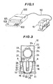
- FIG. 1 An apparatus used to carry out the method of the present invention into effect is shown in FIG. 1 in the form of an overall view. It will be understood that a measuring head 10 is connected to a body 100 by a cable 50.
- the body 100 houses an operation circuit which performs data processing which will be described later, and the body 100 has a display device 101 and a key- board 102, which are electrically connected to the operation circuit, arranged on the front surface thereof.
- a reference numeral 103 designates a main switch which turns a power source ON and OFF.
- a liquid crystal display LCD
- a fluorescent display tube a cathode lay tube (CRT) or the like
- various indication keys, a ten-key and the like are arranged on the keyboard 102.
- the measuring device 10 comprises a base plate 11 and a movable body 20 as shown in FIGS. 2 and 3.
- the base plate 11 is preferably formed of transparent hard plastics or the like such as acrylic plate.
- the base plate is formed in the neighbourhood of one end edge thereof with a measuring hole 13 and has a jig 14 for mounting the movable body secured in the neighbourhood of the other end thereof.
- the jig 14 comprises a bottom plate 15 in contact with the base plate 11 and side plates 16, 16 stood upright on both sides thereof.
- the movable body 20 is rotatably mounted at a point A in the vicinity of the top of the side plates 16, 16. Internally of these two side plates 16, 16 is provided a projection 17 for depressing a limit switch mounted on the side of the movable body 20.
- the whole movable body 20 is covered with a housing 22, within which a measuring device is accommodated.
- a reference numeral 23 designates a photo-multiplier tube and a light receiving surface 24 thereof downwardly faces thereto.
- a light source 25 and a condenser lens 44 which are accommodated within a cylindrical case 26, and an illuminating hole 27 is provided in the lower surface of the cylindrical case 26 so that the light source 25 may illuminate a portion directly thereunder.
- a conical reflecting plate 28 connecting the housing 22, and on the lower end thereof is mounted an objective ring 29 which has a shape so that an outer circumference thereof is fitted into the hole 13.
- a hole 30 of the ring 29 is designed so as to have a dimension which is equal to or somewhat larger than the size of an illumination spot formed by the light source 25.
- a plurality of filter holding plates 32 are mounted on a gear 33, said holding plates 32 holding and successively positioning various filters 31, which are in the illustrated embodiment, an R (red) filter 31 1 ; a G (green) filter 31 2 , a B (blue) filter 31 3 and an amber filter 31 4 .
- filters 31 which are in the illustrated embodiment, an R (red) filter 31 1 ; a G (green) filter 31 2 , a B (blue) filter 31 3 and an amber filter 31 4 .
- four filter holding plates 32 are mounted on the gear 33, for four kinds of filters are used.
- the gear 33 is secured to a rotary shaft 34 supported by bearings 35, and rotation thereof is transmitted by rotation of a rotary shaft 37 of a gear 36 meshed with the gear 33.
- Transmitted to the rotary shaft 37 is a rotational force of a motor 39 by a gear 41 mounted on a rotary shaft 40 of the motor 39 through a gear 38 mounted in the vicinity of one end of the rotary shaft 37.
- a disc.42 . for controlling the amount of rotation of the motor 39 is fixedly mounted on the rotary shaft 40.
- the disc 42 is bored, in the vicinity of the circumference thereof, to make a hole with a spacing which can rotate the gear 33 by 1/4 of one rotation to position the filters 31 immediately before the light receiving surface 24, and a light projecting and receiving element 43 is provided to detect said hole.
- the base plate 11 is first set so that a color specimen to be measured may be exposed from the hole 13.
- the movable body 20 is rotated about the point A by means of a compressive force of a spring coil 45 from the position shown in FIG. 2 in a direction as indicated by arrow B whereby the objective ring 29 is raised from the base plate 11.
- the movable body 20 is depressed and then the lower surface of the objective ring 29 comes into contact with the color specimen to intercept external light, at which time the limit switch 21 is depressed by the projection 17 and turned on whereby measuring starts.
- the light of the light source 25 illuminates only the color specimen exposed from the hole 30 and the reflecting light is reflected by the reflecting plate 28.
- the light passes through the filters 31, reaches the light receiving surface 24 of the photo-multiplier 23 and is converted into an electrical signal corresponding to the intensity of light.
- a central processing unit CPU
- the motor 39 is rotated in accordance with the aforesaid signal.
- the gear 33 is rotated by 1/4 and the next filter 31 2 assumes a position immediately before the light receiving surface 24 for accomplishment of measurement again in a manner similar to that described previously.
- Such an operation is repeatedly carried out till measurement of reflected light of the color specimen through all of.four filters 31 , 31 , 313 and 31 4 and thereby electric signals corresponding to the magnitude of color components of the color specimen may be obtained.
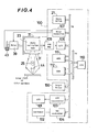
- FIG. 4 is a block diagram for explaining the electric circuit of the apparatus shown in FIG. 4.
- the reflected light of the color chart or color specimen illuminated by the light source 25 passes through the optical filter 31, and only the light of specific color component is received by the photo-multiplier 23 and is converted into an electric signal corresponding to the magnitude of the amount of received light.
- a log amplifier 105 is connected to the photo-multiplier 23, and in the log amplifier 105, the electric signal is converted into color density.
- the color density signal is converted into digital data by an A-D converter and is inputted into CPU 110 through data bus DB.
- a micro-switch 21 Connected to the CPU 110 through the data bus DB are a micro-switch 21, a motor controller 107, a random access memory (RAM) 111, a read only memory (ROM) 112, a liquid crystal display (LCD) controller 103 and a key- board controller 104, which are present within the body 100 or being provided on the body 100.
- RAM random access memory
- ROM read only memory
- LCD liquid crystal display
- the motor controller 107 causes a motor 39 to rotate in accordance with a command from the CPU 110 and causes the motor 39 to stop upon receipt of a signal from a light projecting and receiving element 43.
- a liquid crystal display (LCD) 101 is controlled by the liquid crystal display controller 103 and displays the results of operation made by the CPU 110.
- a key- board 102 is provided to give the CPU 110 date inputs such as data of half-tone do percent of the color chart or various commands.
- a reference numeral 150 designates an external device such as a scanner, which can also directly input into the scanner the half-tone dot percents of various color separations of the obtained color specimen for processing.
- Data fed into the CPU or results operated by the CPU are stored in RAM 111 or ROM 112 through an address bus AB with an address to be stored of RAM 111 or ROM 112 assigned by the CPU 110.
- a combination of color densities of the measured specimen for example, is stored in RAM 111, and programs for actuating, for example, CPU 110, a conversion table of color - half-tone dot percent or the like is stored in ROM 112..
- a table in which color densities of a color chart and half-tone dot percents are combined is prepared, and stored in memory means (ROM 112).
- ROM 112 memory means
- ink of colors, Y, M, C and Bk are used, and the half-tone dot percent of each color separation is varied in suitable spacing between 0% and 100%, 10% in this embodiment, and actual printing is carried out to prepare a color chart.
- Step S 1 a combination of color densities of a color chart is actually successively obtained by the measuring head 10 through the R filter, G filter, B filter and amber filter (an ND filter can be used) (Step S 1 ).
- a combination of half-tone dot percents (which is already known since it is described on the color chart) of each color separation is inputted from the key-board 102 (Step S 2 ).
- the combination of the color densities and the combination of half-tone dot percents are stored in paired relation into a predetermined address of ROM 112 (Step S 3 ). Such processing is carried out for all the color charts (Step S 4 ).
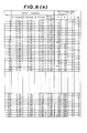
- a conversion table of color density - half-tone dot percent showing the corresponding relation of color densities of color charts and half-tone dot percents of color separations as shown in FIG. 6.
- color separations of M , Y and Bk are 0% in half-tone dot percent and only the C is varied at intervals of 10% between 0% and 100%.
- color separations of Y and Bk are 0% in half-tone dot percent, the M is 10% in half-tone dot percent, and only the C is varied at intervals of 10% between 0% and 100%.
- color separation of Y, M, C and Bk are varied in half-tone dot percent at intervals of 10%. It will be understood that printing is carried out in the mode as just described to obtain a combination of color densities through the R filter, G filter, B filter and amber filter corresponding to each of color chart.
- the measurement of color density through the amber filter need not always be performed but the measurement can be performed by three filters, R filter, G filter and B filter to make a conversion table of color density - hald tone dot percent having three kinds of color densities.
- a means for storing the conversion table of color density - half-tone dot percent is not limited to ROM used in this embodiment but a magnetic disc, a floppy disc or the like can be used.
- the half-tone dot percent of color separations (Y, M, C and Bk) of color specimens are obtained, according to the step shown in Fig. 7.
- a color specimen is put under the base plate 12 of the measuring head 10, and color densities of the color specimen are measured through the R filter, G filter, B filter and amber filter in accordance with the aforementioned measuring operation.
- the filter used for this measurement and the filter used when the conversion table of color density - half-tone dot percent has to be one and the same.
- Each color density is inputted into the CPU (Step S 5 ), and correction calculation is performed with respect to the value thereof (Step S 6 ).
- the correction calculation is performed for the following reason.
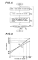
- FIG. 8 is a graphic representation for explaining the relation between the color density and the half-tone dot percent, the axis of ordinate being the color density while the axis of abscissa being the half-tone dot percent. While in the following explanation, a description will be made on the assumption that these are in the linear relation, it will be appreciated that, in even curves, a similar way of thinking can be applied to effect correction.
- color density Xc is obtained by measuring a color chart wherein only the C separation is 100% and all the others are 0% when a conversion table of color density - half-tone dot percent is prepared, through the R filter which is in the relation of complementary color of the C, separation, and color density Nc is obtained through the R filter of a color chart in which all separations are 0%, that is, a portion in which no ink is applied to a paper of the colur chart. Further, a paper to be printed actually is printed beforehand by use of the dot 100% C separation with the density which is determined as the standard dot 100% density in the printing factory.
- color density Xc' is one obtained by measuring the dot 100% density of the C separation applied to the paper to be printed actually by the aforementioned measuring head 10 through the R filter
- color density Nc' is one obtained by measuring the paper, which is not printed, through the R filter in a similar manner.
- the straight lines (a) and (b) respectively indicate the relation between the color density and the half-tone dot percent when a conversion table of color density - half-tone dot percent is prepared and when actual printing is performed, respectively.
- the color specimen is corrected using these color density data with respect to the color densities obtained through the G filter, B filter and amber filter, and the thus corrected color densities DC, D M , Dy and D Bk are used for comparison with the color densities in the conversion table of color density - half-tone dot percent.
- a portion of the dot 100% density of C ink is measured through the R filter, and the color density of the shadow area is adjusted so as to have the color density of R filter where the C of the conversion table of color density - half-tone dot percent is 100% (which is the case of number 11 in FIG. 6).
- M ink, Y ink and Bk ink are also measured through the G filter, B filter, and amber filter so as to have color densities of the G filter, B filter and amber filter where color separations of Y, M and Bk of the conversion table of color density - half-tone dot percent.
- the thus corrected color density of the color specimen is compared with the color densities of the conversion table of color density - half-tone dot percent. That is, color density data are read from number 1 thereof into CPU 110 from the conversion table of color density - half-tone dot percent which is being stored in ROM shown in FIG. 6 (Step S 7 ), and the distance calculation relative to each color density of color specimen is performed (St p S 8 ).
- the distance calculation is performed in the following, if an equation is used.
- D R , D G , D B and DA be the densities obtained through the R filter, G filter, B filter and amber filter, respectively, of the color specimen
- T R (n), T G (n), T B (n) and T A (n) be the color densities through the R filter, G filter, B filter and amber filter, respectively, in the n th number of the conversion table of color density - half-tone dot percent.
- the distance S A (n) between both the elements may be obtained by the equation:
- Step S 10 Since the distance S A (1) between the color density of color specimen and the 1st color density in the table is so far subjected to distance calculation, it is the minimum in Step S 9 , and so said number and the calculated distance are stored in a predetermined address of RAM (Step S 10 ). The value is judged if it is 0 or not with respect to the distance (Step S 11 ). If it is 0, the distance calculation with respect to the other color density stops at that time and the half-tone dot percent corresponding to that number calls up from the coversion table of color density - half-tone dot percent (Step S 13 ).
- Step S 9 a combination of the 2nd color density is read from the conversion table of color density - half-tone dot percent and similar distance calculation is performed to obtain the distance with respect to the color density of cilor specimen, after which that distance is compared with the 1st distance being stored in RAM 111 (Step S 9 ); and number of smaller distance and the distance are stored (Step S 10 ).
- the color density of color specimen is subjected to distance calculation with respect to all combinations of color densities of the conversion table of color density - half-tone dot percent to thereby obtain combination- number of color density of the smallest distance.
- a combination of half-tone dot percents corresponding to that number is extracted from the'conversion table of color density - half-tone dot percent to thereby obtain the half-tone dot percents of color separations of Y, M, C and Bk of the measured color specimen.
- the accuracy of the half-tone dot percent obtained in a manner as described above depends on with what accuracy the half-tone dot percent in the conversion table of color density - half-tone dot percent is prepared. Since in the example shown in FIG. 6, the half-tone dot percent is prepared so that it is varied at intervals of 10%, the accuracy is up to 10%.
- a conversion table of color density - half-tone dot percent of accuracy required can be prepared but if so prepared, there arises disadvantages that data of the conversion table of color density - half-tone dot percent becomes extremely increased, that it takes much time to prepare such data, and that a memory having a large memory capacity is not only required but it also takes time for comparison with the measured data of color specimen.
- FIG. 9 shows a flow chart showing the aforesaid processing procedure. Since Steps of S 14 to S21 can be executed exactly in the same manner as that of Steps of S 5 to S 12 in FIG. 7, further explanation will not be made. Also in the event the distance is 0, the half-tone dot percent of that number can be extracted from the table to complete processing in a similar manner. It is noted that a conversion table of color density - half-tone dot percent similar to that shown in.FIG. 6 may be used.
- Step S 22 the color density of number wherein said distance is the smallest and the half-tone dot percent are read into CPU 110 from the conversion table of color density - half-tone dot percent (Step S 22 ), and the interpolation calculation is performed (Step S 23 ) whereby a half-tone dot percent which is smaller between the densities, in other words, is more approximate, may be obtained.
- t(T R , T , T B , T ) be the combination of the aforesaid read color densities
- P(c, m, y, bk) be the combination of half-tone dot percent
- d(R , D , D B , D ) be the combination of color densities of color specimen.
- the half-tone dot percent is obtained in accuracy up to 1%.
- the half-tone dot percent is varied at intervals of 10%, a half-tone dot percent to be obtained is present away large and small by a half of 10%, namely, 5% of the half-tone dot percent of each color separation around P.
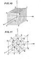
- FIG. 10 represents points wherein color separations of C, M and Y are deviated (+) 5% around P (c, m, y), in the C, M, Y coordinate system, each showing points of A(c+5, m-5, y+5), B(c+5, m+5, y+5), C(c+5, m+5, y-5), D(C+5, m-5, y-5), E(C-5, m-5, y+5), F(c-5, m+5, y+5), G(c-5, m+5, y-5) and H(c-5, m-5, y-5).
- the half-tone dot percent to be obtained is present in a color space with these points as apexes.
- the color space is divided as shown in FIG. 10 for every necessary accuracy (1% in this case), a combination of color densities are obtained for every combination of half-tone dot percent shown by each grid point, and a point wherein the distance is the smallest is selected by the aforementioned formula used to obtain the distance of the color density whereby a combination of half-tone dot percents at that point can be determined as a combination of half-tone dot percents with accuracy increased.
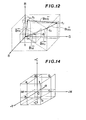
- FIG. 11 shows positions of the points 10% away from the point P in the C, M, Y coordinate system which represents the half-tone dot percent.
- the point A is at a position of the center of the color space composed of points A'(c+10, m-10, y+10), M(c+10, m, y+10), Z(c+10, m, y), Q(c+10, m-10, y), I(c, m-10, y+10), R(c, m, y+10), P(c, m, y) and U(c, m-10, y) in FIG. 11.
- an average every color density component of the points A', M, Z, Q, I, R, P and U is obtained, and that value is used as the color density component of the point A, that is, as the combination of color density of the point A.
- a color space composed of the points A', M, Z, Q, I, R, P and U is sometimes not a cubic body but a rectangular hexahedron, in which case, the distance of the point A from each of apexes of the rectangular hexahedron is different, and therefore, a proportional formula or proper functions can be used according to the distance from each apex.
- a combination of half-tone dot percents can be used as a combination of half-tone dot percents necessary for reproducing color assigned by color specimen to thereby obtain the measured result of higher accuracy than that obtained by the aforementioned method.
- FIG. 12 illustrates another interpolation method.
- color densities obtained through the R, G and B filters, respectively are represented with a combination t (T R , T G , T B ) of color densities wherein the distance relative to the color specimen is the smallest.
- Character d represents the point showing a combination (D R , D G , D B ) of color densities of color specimen.
- a combination of P 3 (c+10, m+10, y+10) of half-tone dot percents each deviated by one unit (that is, 10% in case of FIG. 6) relative to a combination P (c, m, y) of half-tone dot percents corresponding to the combination t of color densities is set, and a combination t 3 (T R3 ' T G3 ' T B3 ) of color densities corresponding thereto can be known from the conversion table of color densities - half-tone dot percent.
- the vector can be represented as a combination of several vectors.
- P 1 (c+10, m, y ) and P 2 (c+10, m+10, y) be the combinations of half-tone dot percent for the cases where component c is large by 10% and component m is large by 10%, respectively, relative to the combination P (c, m, y) of half-tone dot percent.
- the combinations of color densities corresponding to the combinations P 1 , P 2 of half-tone dot percent may be known as t 1 (T R1 , T G1 , T Bl ) and t 2 (T R2 , T G2 , T B2 ), respectively, from the conversion table of color density - half-tone dot percent.
- the vector may be represented as by the vectors and
- the vector B td is represented as Since the vector is known in component as previously described, ⁇ , ⁇ and y are obtained by the above-described formula.
- a combination P' (c', m', y') of half-tone dot percents wherein a combination P (c, m, y) of half-tone dot percents corresponding to t is interpolated relative to a combination of color densities selected as one which is the closest to the combination d (D R , D G , D ) of color densities of color specimen, is as follows: B because the table of FIG. 6 is at intervals of 10%.
- a vector is selected so that a vector obtained by connecting a combination of color densities obtained from the conversion table of color density - half-tone dot percent, as shown in FIG. 12, reaches a combination t of color densities.
- processing time required for interpolation for obtaining a combination of half-tone dot percents of high accuracy as described above may be extremely shortened.
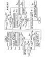
- FIG. 13 shows the processing procedure of this method.
- Steps S 25 to S 32 are similar to Steps S 5 to S 12 shown in FIG. 7, and therefore, explanation thereof will be omitted.
- Step S34 a combination t(T , T G , T B , T A ) of color densities of number (in which distance is 0 or smallest) most approximate to a combination d (D R , D G , DB , D A ) of color densities of color specimen and a combination P (c, m, y, bk) of half-tone dot percents are read into CPU 110.
- Color densities of grid points are obtained by interpolation, in a manner similar to that as described above, a combination of color densities thus interpolated is used to select a point where the distance is the smallest in the above-described formula of distance calculation, and the value of P is corrected by the value of said point to obtain a combination of half-tone dot percents which is satisfied with necessary accuracy.
- variation in density is (-0.09, -0.04, -0.07) from the density value (0.26, 1.39, 0.78) of a combination (10, 100, 0) of half-tone dot percents and the density value (0.17, 1.35, 0.71) of a combination (0, 100, 0) of half-tone dot percents.
- the density of the combination (-10, 100, 0) of half-tone dot percents to be obtained is (0.08, 1.31, 0.64) wherein the density value of the combination (0, 100, 0) of half-tone dot percents is varied at the proportion of that variation.
- the density of the point of 110% can be varied at the proportion in increase from 90% to 100%. While in the above-described embodiment, only variations from 10 to 0% or 90 to 100% have been obtained, it should be noted that functions are obtained at several point within the color space, for example, three points, 20, 10 and 0% to obtain the density of the point of -10%.
- FIG. 14 A model view of thus obtained expanded color space is shown in FIG. 14.
- a point where the distance is the smallest is selected by the aforementioned formula for obtaining the distance between a point indicated at each grid point and the measured value, and the half-tone dot percent of P can be interpolated by the value of the selected point (Steps S37, S38, S42 and S43).
- a combination of half-tone dot percents after interpolation is in a color space, that is, the half-tone dot percent of each color has to be between 0 and 100%. Even 1% is outside the color space unless an error such as an measured error of color density is present, it will be a color that may not be reproduced with predetermined ink. However, if a density value is employed as color information, the measuring accuracy is approximately + 0.02 in density value. When the density value is varied through 0.02 on the side where color is light, the half-tone dot percent varies by about 3%.
- Steps S39 and S40 even if the combination of half-tone dot percents after correction has the value outside the color space by about 3%, color can be judged to be a reproducible color. However, if there is a difference more than that,as described, it can not be disregarded and color cannot be reproduced. The smaller than 0% or the larger than 100%, the combination is moved away from the color space, as a consequence of which the fact that it is hard to reproduce it as color can be quantitatively shown.
- the propriety of color reproduction of the color specimen by the predetermined ink can be discriminated by displaying the obtained half-tone dot percent (Steps S41 and S44).
- the half-tone dot percent can be obtained by the already described vector procedure.
- a combination of half-tone dot percents obtained by measuring the color specimen as described above can be also displayed on the liquid crystal display 101 or be inputted into the external device 150 such as a scanner to directly place it at reproduction work.
- the color specimen can be measured to accurately obtain a half-tone dot percent of each color separation.
- a color assigned by a color specimen is a color which is difficult to reproduce by the gathering-printing using ink of colors, for example, Y, M, C and Bk
- a half-tone dot percent of color separation of color most approximate to such color may be of course obtained, and in addition, the conception of the half-tone dot percent can be expanded to know to what extent reproduction is difficult.
Landscapes
- Physics & Mathematics (AREA)
- General Physics & Mathematics (AREA)
- Facsimile Image Signal Circuits (AREA)
- Spectrometry And Color Measurement (AREA)
- Color Image Communication Systems (AREA)
Applications Claiming Priority (2)
| Application Number | Priority Date | Filing Date | Title |
|---|---|---|---|
| JP58081561A JPS59206839A (ja) | 1983-05-10 | 1983-05-10 | 網点面積率入力装置 |
| JP81561/83 | 1983-05-10 |
Publications (3)
| Publication Number | Publication Date |
|---|---|
| EP0124908A2 true EP0124908A2 (de) | 1984-11-14 |
| EP0124908A3 EP0124908A3 (en) | 1986-11-26 |
| EP0124908B1 EP0124908B1 (de) | 1991-09-18 |
Family
ID=13749698
Family Applications (1)
| Application Number | Title | Priority Date | Filing Date |
|---|---|---|---|
| EP84105255A Expired EP0124908B1 (de) | 1983-05-10 | 1984-05-09 | Verfahren zur Gewinnung von Rasterpunkt-Prozentwerten für genaue Farbwiedergabe |
Country Status (4)
| Country | Link |
|---|---|
| US (1) | US4717954A (de) |
| EP (1) | EP0124908B1 (de) |
| JP (1) | JPS59206839A (de) |
| DE (1) | DE3485069D1 (de) |
Cited By (4)
| Publication number | Priority date | Publication date | Assignee | Title |
|---|---|---|---|---|
| EP0321402A1 (de) * | 1987-12-16 | 1989-06-21 | GRETAG Aktiengesellschaft | Verfahren zur Farbsteuerung oder Farbregelung einer Druckmaschine |
| US4852485A (en) * | 1985-03-21 | 1989-08-01 | Felix Brunner | Method of operating an autotypical color offset printing machine |
| DE4402784A1 (de) * | 1994-01-31 | 1995-10-12 | Wifag Maschf | Qualitätsdatenerfassung im Rollenoffset-Auflagendruck |
| US9346259B2 (en) | 2010-02-08 | 2016-05-24 | Heidelberger Druckmaschinen Ag | Ink control method for printing presses having short inking units |
Families Citing this family (58)
| Publication number | Priority date | Publication date | Assignee | Title |
|---|---|---|---|---|
| US4839721A (en) * | 1984-08-28 | 1989-06-13 | Polaroid Corporation | Method of and apparatus for transforming color image data on the basis of an isotropic and uniform colorimetric space |
| DE3539540A1 (de) * | 1984-11-08 | 1986-05-22 | Canon K.K., Tokio/Tokyo | Farbbildbehandlungsverfahren |
| US5182721A (en) * | 1985-12-10 | 1993-01-26 | Heidelberger Druckmaschinen Aktiengesellschaft | Process and apparatus for controlling the inking process in a printing machine |
| GB8601176D0 (en) * | 1986-01-17 | 1986-02-19 | Infrared Eng Ltd | Sensing |
| DE3626423A1 (de) * | 1986-08-05 | 1988-02-11 | Deutsche Forsch Druck Reprod | Verfahren und vorrichtung zur beeinflussung der farblichen erscheinung einer farbflaeche bei einem druckvorgang |
| JPS63191041A (ja) * | 1987-02-03 | 1988-08-08 | Komori Printing Mach Co Ltd | 濃度測定位置合わせ方法 |
| JPS63228882A (ja) * | 1987-03-17 | 1988-09-22 | Minolta Camera Co Ltd | 画像信号処理方式 |
| US4947348A (en) * | 1987-03-25 | 1990-08-07 | Kollmorgen Corporation | Densitometer method and system for identifying and analyzing printed targets |
| DE3854851T2 (de) * | 1987-08-11 | 1996-10-17 | Canon Kk | Vorrichtung zur Herstellung von Farbbildern |
| US5181014A (en) * | 1987-10-26 | 1993-01-19 | Tektronix, Inc. | Method and apparatus for representing three-dimensional color data in a one-dimensional reference system |
| US4839722A (en) * | 1987-10-30 | 1989-06-13 | Colorocs Corporation | Method and apparatus for providing improved color correction in a subtrative color printing system |
| US5335095A (en) * | 1987-12-16 | 1994-08-02 | Minolta Camera Kabushiki Kaisha | Image forming apparatus capable of editing color image |
| ES2033128T3 (es) * | 1988-01-14 | 1993-03-01 | Gretag Aktiengesellschaft | Procedimiento y dispositivo para regular el calor de una maquina impresora. |
| US5081528A (en) * | 1988-03-10 | 1992-01-14 | Canon Kabushiki Kaisha | Image forming apparatus |
| US5081527A (en) * | 1988-04-12 | 1992-01-14 | Minolta Camera Kabushiki Kaisha | Digital image forming apparatus |
| US4959790A (en) * | 1988-06-28 | 1990-09-25 | F & S Corporation Of Columbus, Georgia | Apparatus and method for producing color corrected reproduction of colored original images |
| EP0359869A1 (de) * | 1988-08-23 | 1990-03-28 | Agfa-Gevaert N.V. | Verfahren für Farbkorrektur nach der Trockenätzmethode mittels einer photographisch angefertigten Maske |
| US4918622A (en) * | 1988-11-16 | 1990-04-17 | Eastman Kodak Company | Electronic graphic arts screener |
| US4916545A (en) * | 1988-11-16 | 1990-04-10 | Eastman Kodak Company | Electronic graphic arts screener that suppresses Moire patterns using pseudo-random font selection |
| US4977458A (en) * | 1988-11-16 | 1990-12-11 | Eastman Kodak Company | Apparatus for addressing a font to suppress Moire patterns occurring thereby and a method for use therein |
| US5121196A (en) * | 1988-11-18 | 1992-06-09 | Konica Corporation | Color processing method and apparatus with a color patch |
| US5130701A (en) * | 1989-05-12 | 1992-07-14 | The United States Of America As Represented By The United States Department Of Energy | Digital color representation |
| US5274473A (en) * | 1989-08-04 | 1993-12-28 | Intergraph Corporation | Rapid variable angle digital screening |
| ATE156642T1 (de) * | 1990-02-05 | 1997-08-15 | Scitex Corp Ltd | Farbeichungsgerät und -verfahren |
| CA2035666A1 (en) * | 1990-02-05 | 1991-08-06 | Ehud Spiegel | Apparatus and techniques for processing of data such as color images |
| JPH0775392B2 (ja) * | 1990-06-19 | 1995-08-09 | 富士ゼロックス株式会社 | 画像処理装置 |
| JP2855008B2 (ja) * | 1990-10-03 | 1999-02-10 | 富士写真フイルム株式会社 | 画像処理方法および装置 |
| US5174758A (en) * | 1990-12-11 | 1992-12-29 | Abramson Steven J | Color selector for four-color offset printing, and method of creating it |
| US5272518A (en) * | 1990-12-17 | 1993-12-21 | Hewlett-Packard Company | Colorimeter and calibration system |
| IL98622A (en) * | 1991-06-25 | 1996-10-31 | Scitex Corp Ltd | Method and device for using neural networks in figure work |
| US5315380A (en) * | 1991-08-23 | 1994-05-24 | Iris Graphics Inc. | Apparatus and method for transforming the digital representation of a color input image |
| US5251271A (en) * | 1991-10-21 | 1993-10-05 | R. R. Donnelley & Sons Co. | Method for automatic registration of digitized multi-plane images |
| US5481655A (en) * | 1992-09-18 | 1996-01-02 | Iris Graphics, Inc. | System for matching a picture on a monitor to a printed picture |
| US5748195A (en) * | 1992-10-29 | 1998-05-05 | International Business Machines Corporation | Method and means for evaluating a tetrahedral linear interpolation function |
| US5432892A (en) * | 1992-11-25 | 1995-07-11 | International Business Machines Corporation | Volummetric linear interpolation |
| US5390035A (en) * | 1992-12-23 | 1995-02-14 | International Business Machines Corporation | Method and means for tetrahedron/octahedron packing and tetrahedron extraction for function approximation |
| US5751926A (en) * | 1992-12-23 | 1998-05-12 | International Business Machines Corporation | Function approximation using a centered cubic packing with tetragonal disphenoid extraction |
| US5357448A (en) * | 1993-02-02 | 1994-10-18 | Quad/Tech, Inc. | Method and apparatus for controlling the printing of an image having a plurality of printed colors |
| US5677967A (en) * | 1993-03-10 | 1997-10-14 | R. R. Donnelley & Sons Company | Method of and apparatus for converting between a color appearance space and a colorant space |
| US5666436A (en) * | 1993-10-14 | 1997-09-09 | Electronics For Imaging | Method and apparatus for transforming a source image to an output image |
| DE4431270C2 (de) * | 1993-10-21 | 1997-01-16 | Roland Man Druckmasch | Verfahren zur Steuerung der Farbführung einer autotypisch arbeitenden Druckmaschine |
| US6002498A (en) * | 1994-06-15 | 1999-12-14 | Konica Corporation | Image processing method and image forming method |
| US6301025B1 (en) * | 1994-06-24 | 2001-10-09 | Mgi Software Corporation | Method for performing a color space transformation |
| DE19506425B4 (de) * | 1995-02-24 | 2004-11-18 | Heidelberger Druckmaschinen Ag | Offsetdruckverfahren |
| US5852675A (en) * | 1995-04-14 | 1998-12-22 | Kiyoshi Matsuo | Color chart for image correction and method of color correction |
| US5781206A (en) * | 1995-05-01 | 1998-07-14 | Minnesota Mining And Manufacturing Company | Apparatus and method for recalibrating a multi-color imaging system |
| US6137494A (en) * | 1995-08-18 | 2000-10-24 | International Business Machines Corporation | Method and means for evaluating a tetrahedral linear interpolation function |
| US5748330A (en) * | 1997-05-05 | 1998-05-05 | Xerox Corporation | Method of calibrating a digital printer using component test patches and the yule-nielsen equation |
| US5819655A (en) * | 1997-08-20 | 1998-10-13 | Bristol-Myers Squibb Company | Cyclinder color printing method and product using improved misregistration detection |
| US6801336B1 (en) * | 1999-08-30 | 2004-10-05 | Creo Inc. | System and method for producing halftoned color separations for an output imaging device |
| US7375857B1 (en) | 2000-09-22 | 2008-05-20 | Eastman Kodak Company | Print proofing with color and screen matching |
| JP2002142125A (ja) * | 2000-10-31 | 2002-05-17 | Fuji Photo Film Co Ltd | カラーチャート、チャート画像データ記録媒体、プロファイル作成装置、プロファイル作成方法、およびプロファイル作成プログラム記憶媒体 |
| WO2002070261A1 (en) * | 2001-03-02 | 2002-09-12 | The Ackley Martinez Company Dba Mgi Studio | Printing adjustment system and method |
| CA2452543A1 (en) | 2001-07-30 | 2003-03-13 | The Ackley Martinez Company Dba Mgi Studio | System admixture compensation system and method |
| BR0211123A (pt) * | 2001-07-30 | 2004-10-26 | Ackley Martinez Company Dba Mg | Sistema e método de processamento de gerenciamento de cor |
| US6786565B2 (en) | 2001-09-24 | 2004-09-07 | Creo Americas, Inc. | Inkjet proofing with matched color and screen resolution |
| US7605959B2 (en) | 2005-01-05 | 2009-10-20 | The Ackley Martinez Company | System and method of color image transformation |
| JP2007256251A (ja) * | 2006-02-24 | 2007-10-04 | Hitachi High-Technologies Corp | データ収集処理装置 |
Family Cites Families (17)
| Publication number | Priority date | Publication date | Assignee | Title |
|---|---|---|---|---|
| US3612753A (en) * | 1969-04-23 | 1971-10-12 | Ventures Res & Dev | Self-adaptive system for the reproduction of color |
| JPS4818230U (de) * | 1971-07-13 | 1973-03-01 | ||
| US3893166A (en) * | 1972-01-05 | 1975-07-01 | Crosfield Electronics Ltd | Colour correcting image reproducing methods and apparatus |
| GB1527227A (en) * | 1974-12-18 | 1978-10-04 | Crosfield Electronics Ltd | Reproduction of coloured images |
| DE2526409C3 (de) * | 1975-06-13 | 1979-08-09 | Dr.-Ing. Rudolf Hell Gmbh, 2300 Kiel | Verfahren zur Eichung einer eine fotomechanische Druckform erzeugenden Aufzeichnungseinheit |
| JPS5224701A (en) * | 1975-08-20 | 1977-02-24 | Dainippon Screen Mfg | Method of correcting color of image signal |
| DE2628053C2 (de) * | 1976-06-23 | 1978-06-15 | Dr.-Ing. Rudolf Hell Gmbh, 2300 Kiel | Schaltungsanordnung zum Erkennen von Farben |
| DE2810225C2 (de) * | 1978-03-09 | 1982-04-22 | Dr.-Ing. Rudolf Hell Gmbh, 2300 Kiel | Gewinnung und Verwertung von Farbkorrekturdaten für die Farbbildaufzeichnung |
| US4275413A (en) * | 1978-03-30 | 1981-06-23 | Takashi Sakamoto | Linear interpolator for color correction |
| CH646788A5 (de) * | 1978-11-28 | 1984-12-14 | Hell Rudolf Dr Ing Gmbh | Verfahren und schaltungsanordnung zum erkennen von farben. |
| DE3024459A1 (de) * | 1979-07-03 | 1981-01-08 | Crosfield Electronics Ltd | Pyramideninterpolation |
| JPS55109936A (en) * | 1980-01-07 | 1980-08-23 | Daihen Corp | Colorimetric display unit |
| US4477833A (en) * | 1981-08-12 | 1984-10-16 | R. R. Donnelley & Sons Company | Method of color conversion with improved interpolation |
| DE3268379D1 (en) * | 1982-06-04 | 1986-02-20 | Hell Rudolf Dr Ing Gmbh | Process and device for the preparation of coloured proofs in multicolour printing |
| US4481532A (en) * | 1982-06-28 | 1984-11-06 | R. R. Donnelley & Sons Company | Method of determining and storing color printing information |
| JPS5935116A (ja) * | 1982-08-24 | 1984-02-25 | Mitsubishi Rayon Co Ltd | カラ−センサ |
| GB8307290D0 (en) * | 1983-03-16 | 1983-04-20 | Phillips G L P | Colour printing process |
-
1983
- 1983-05-10 JP JP58081561A patent/JPS59206839A/ja active Granted
-
1984
- 1984-05-08 US US06/608,230 patent/US4717954A/en not_active Expired - Fee Related
- 1984-05-09 DE DE8484105255T patent/DE3485069D1/de not_active Expired - Lifetime
- 1984-05-09 EP EP84105255A patent/EP0124908B1/de not_active Expired
Cited By (5)
| Publication number | Priority date | Publication date | Assignee | Title |
|---|---|---|---|---|
| US4852485A (en) * | 1985-03-21 | 1989-08-01 | Felix Brunner | Method of operating an autotypical color offset printing machine |
| EP0321402A1 (de) * | 1987-12-16 | 1989-06-21 | GRETAG Aktiengesellschaft | Verfahren zur Farbsteuerung oder Farbregelung einer Druckmaschine |
| DE4402784A1 (de) * | 1994-01-31 | 1995-10-12 | Wifag Maschf | Qualitätsdatenerfassung im Rollenoffset-Auflagendruck |
| DE4402784C2 (de) * | 1994-01-31 | 2001-05-31 | Wifag Maschf | Messfeldgruppe und Verfahren zur Qualitätsdatenerfassung unter Verwendung der Messfeldgruppe |
| US9346259B2 (en) | 2010-02-08 | 2016-05-24 | Heidelberger Druckmaschinen Ag | Ink control method for printing presses having short inking units |
Also Published As
| Publication number | Publication date |
|---|---|
| JPH0522227B2 (de) | 1993-03-26 |
| JPS59206839A (ja) | 1984-11-22 |
| EP0124908A3 (en) | 1986-11-26 |
| DE3485069D1 (de) | 1991-10-24 |
| EP0124908B1 (de) | 1991-09-18 |
| US4717954A (en) | 1988-01-05 |
Similar Documents
| Publication | Publication Date | Title |
|---|---|---|
| EP0124908A2 (de) | Verfahren zur Gewinnung von Rasterpunkt-Prozentwerten für genaue Farbwiedergabe | |
| EP0706285B1 (de) | Bildverarbeitungsvorrichtung und -verfahren | |
| US4941038A (en) | Method for color image processing | |
| US4956703A (en) | Print simulation apparatus for adjusting the color separation conditions of a color scanner | |
| US5347369A (en) | Printer calibration using a tone reproduction curve and requiring no measuring equipment | |
| US4393399A (en) | Method and apparatus for partial electronic retouching of colors | |
| US4884130A (en) | Method of describing a color in a triaxial planar vector color space | |
| US5841955A (en) | Control system for a printing press | |
| CN101730626B (zh) | 中性灰色平衡质控方法 | |
| JP2013514678A (ja) | 多原色印刷の品管方法 | |
| US6084693A (en) | Process and apparatus for the determination of halftone percentage values | |
| US5816151A (en) | Device for alignment of images in a control system for a printing press | |
| EP0546112B1 (de) | Verfahren zur erzeugung von mehrfarbigen halbtongerasterten reproduktionen aus einfarbigen grautonoriginalen | |
| US5475496A (en) | Image processing apparatus for binarizing multi-value image data | |
| US6262808B1 (en) | Multicolor printing process, especially a multicolor grid screen printing process for textile substrates | |
| US6522338B1 (en) | Method of color matching between color image processing devices, by interpolation of relatively small number of color data sets | |
| JPH0449104B2 (de) | ||
| JPH0767130B2 (ja) | 網点面積率決定装置 | |
| JPS60259903A (ja) | 網点面積率決定装置 | |
| JPH0526184B2 (de) | ||
| JPH0663844B2 (ja) | カラーマトリクススケールの作成方法 | |
| JPH0376633B2 (de) | ||
| JPH0650391B2 (ja) | 網点面積率決定装置 | |
| JPS60142206A (ja) | 網点面積率決定装置 | |
| JPH0650390B2 (ja) | 網点面積率決定装置 |
Legal Events
| Date | Code | Title | Description |
|---|---|---|---|
| PUAI | Public reference made under article 153(3) epc to a published international application that has entered the european phase |
Free format text: ORIGINAL CODE: 0009012 |
|
| AK | Designated contracting states |
Designated state(s): DE FR GB |
|
| 17P | Request for examination filed |
Effective date: 19850423 |
|
| PUAL | Search report despatched |
Free format text: ORIGINAL CODE: 0009013 |
|
| AK | Designated contracting states |
Kind code of ref document: A3 Designated state(s): DE FR GB |
|
| 17Q | First examination report despatched |
Effective date: 19881104 |
|
| GRAA | (expected) grant |
Free format text: ORIGINAL CODE: 0009210 |
|
| AK | Designated contracting states |
Kind code of ref document: B1 Designated state(s): DE FR GB |
|
| REF | Corresponds to: |
Ref document number: 3485069 Country of ref document: DE Date of ref document: 19911024 |
|
| ET | Fr: translation filed | ||
| PLBE | No opposition filed within time limit |
Free format text: ORIGINAL CODE: 0009261 |
|
| STAA | Information on the status of an ep patent application or granted ep patent |
Free format text: STATUS: NO OPPOSITION FILED WITHIN TIME LIMIT |
|
| 26N | No opposition filed | ||
| PGFP | Annual fee paid to national office [announced via postgrant information from national office to epo] |
Ref country code: GB Payment date: 19930428 Year of fee payment: 10 |
|
| PGFP | Annual fee paid to national office [announced via postgrant information from national office to epo] |
Ref country code: FR Payment date: 19930510 Year of fee payment: 10 |
|
| PGFP | Annual fee paid to national office [announced via postgrant information from national office to epo] |
Ref country code: DE Payment date: 19930524 Year of fee payment: 10 |
|
| PG25 | Lapsed in a contracting state [announced via postgrant information from national office to epo] |
Ref country code: GB Effective date: 19940509 |
|
| GBPC | Gb: european patent ceased through non-payment of renewal fee |
Effective date: 19940509 |
|
| PG25 | Lapsed in a contracting state [announced via postgrant information from national office to epo] |
Ref country code: FR Effective date: 19950131 |
|
| PG25 | Lapsed in a contracting state [announced via postgrant information from national office to epo] |
Ref country code: DE Effective date: 19950201 |
|
| REG | Reference to a national code |
Ref country code: FR Ref legal event code: ST |