EP0122883A2 - Procédé d'assemblage mécanique des barres d'un treillis et appareil d'assemblage mécanique des barres d'un treillis - Google Patents
Procédé d'assemblage mécanique des barres d'un treillis et appareil d'assemblage mécanique des barres d'un treillis Download PDFInfo
- Publication number
- EP0122883A2 EP0122883A2 EP84810183A EP84810183A EP0122883A2 EP 0122883 A2 EP0122883 A2 EP 0122883A2 EP 84810183 A EP84810183 A EP 84810183A EP 84810183 A EP84810183 A EP 84810183A EP 0122883 A2 EP0122883 A2 EP 0122883A2
- Authority
- EP
- European Patent Office
- Prior art keywords
- binding element
- preferably according
- rods
- rod
- templates
- Prior art date
- Legal status (The legal status is an assumption and is not a legal conclusion. Google has not performed a legal analysis and makes no representation as to the accuracy of the status listed.)
- Withdrawn
Links
Images


Classifications
-
- B—PERFORMING OPERATIONS; TRANSPORTING
- B21—MECHANICAL METAL-WORKING WITHOUT ESSENTIALLY REMOVING MATERIAL; PUNCHING METAL
- B21F—WORKING OR PROCESSING OF METAL WIRE
- B21F23/00—Feeding wire in wire-working machines or apparatus
- B21F23/005—Feeding discrete lengths of wire or rod
-
- B—PERFORMING OPERATIONS; TRANSPORTING
- B21—MECHANICAL METAL-WORKING WITHOUT ESSENTIALLY REMOVING MATERIAL; PUNCHING METAL
- B21F—WORKING OR PROCESSING OF METAL WIRE
- B21F27/00—Making wire network, i.e. wire nets
- B21F27/08—Making wire network, i.e. wire nets with additional connecting elements or material at crossings
-
- E—FIXED CONSTRUCTIONS
- E04—BUILDING
- E04C—STRUCTURAL ELEMENTS; BUILDING MATERIALS
- E04C5/00—Reinforcing elements, e.g. for concrete; Auxiliary elements therefor
- E04C5/01—Reinforcing elements of metal, e.g. with non-structural coatings
- E04C5/02—Reinforcing elements of metal, e.g. with non-structural coatings of low bending resistance
- E04C5/04—Mats
Definitions
- the present invention relates to a method for mechanically connecting the rods of a rod network, in which a wire-shaped binding element is fed to an intersection, fixed there and a segment is separated therefrom and the connection is established with the latter, and a system for mechanically connecting the rods of a rod network to a feed arrangement for a wire-shaped binding element, fixing elements and severing elements for the binding element in the area of a rod crossing point as well as with connecting elements in crossing point areas for the rod connection by means of separated binding element segments.
- a method of the type mentioned is known from AT-PS 363 765.
- Two tie wires are fed to each crossing point of the reinforcing mesh longitudinal and transverse bars, by pulling the ends of these away from the corresponding supplies and specifically feeding these ends to each crossing point.
- This means that the binding wire ends must be selectively fed to each of a multiplicity of crossing points to be connected, and that two ent for each of the crossing points to be connected simultaneously speaking supply devices for the element must be provided.
- a terminal section is cut off from each of the two binding wire ends fed to each crossing point, bent agraff-shaped, placed over the assigned crossing point and finally twisted in a rod-connecting manner.
- the primary disadvantage of this technology is that the end of a binding wire is fed to each crossing point, with the resulting complexity of a system which simultaneously executes the known method at a large number of crossing points.
- the aim of the present invention is to further develop the above-mentioned method in such a way that the binding wire feed is considerably simplified.
- the feed device comprises a feed carriage which is driven through a plurality of intersection areas and which, with gripping members for the wire-shaped binding element, runs the latter over a plurality of intersection areas.
- the system according to the invention only makes it possible to create a system by means of appropriate further development according to the invention which can quickly, practically in continuous operation, tie large-area networks.
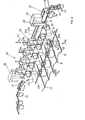
- Fig. 1 the manufacturing plant is shown schematically in supervision.
- a storage zone 1 longitudinal bars 5 or transverse bars 7 to be processed are stacked between rows of bearing posts 3 which project vertically on the floor.
- a traveling crane 9 is arranged above the storage zone 1, with the aid of which longitudinal rods 5 or transverse rods 7 are raised in a manner to be described.
- the longitudinal rods 5 After the longitudinal rods 5 have been lifted, they are first cut to the desired length by means of cutting elements on the overhead crane 9, then conveyed onto a longitudinal rod overhead crane 13 by means of a roller feed mechanism 11. After the longitudinal rods 5 have been taken over by the overhead crane 9, the longitudinal rod overhead crane 13 moves in the direction indicated by S 1 over a longitudinal rod bed 15 of the production system.
- the longitudinal bar bed 15 is formed in cross-section like a corrugated sheet, with guide grooves 17, in which the longitudinal bar overhead crane 13 distributes the longitudinal bars 5.
- a rake-like feed arrangement 19 pushes the longitudinal rods 5 deposited in the guide channels 17 in the direction indicated by S 2 against the production zone 21.
- two binding banks 23a and 23b are arranged.
- a cross bar overhead crane 25 is provided on a level higher with respect to the longitudinal bar overhead traveling crane 13 on its running rails 13a, 13b.
- a cross bar overhead crane 25 is provided on the one hand, it is displaceable on rails 25a, 25b parallel to the guide channels 17 of the longitudinal rod bed 15, as indicated by S 3 , and comprises a crane truck 27 which is displaceable in the direction indicated by S 4 on the bridge 26 which can be displaced in the direction S 3 , and which, as shown by S 5 , is also pivotable about a vertical axis 29.
- the cross bars 7 are raised in an analogous manner to the longitudinal bars 5, cut to the correct length if necessary, and conveyed to the crane truck 27 in the position shown with the roller feed mechanism 11.
- the longitudinal rods 5 advanced in saccades are connected to the transverse rods 7 deposited there by pulling binding wire out of binding wire stocks 31, as will be described later, into agraffes, preferably from above the crossing points of cross and longitudinal bars 7, 5 are placed and then twisted below.
- the cross bars 7 on the longitudinal bars 5 feeding the clasps from above, twisting their ends at the bottom, there are twisted braids which project downward from the longitudinal bars. In practice, this is of great advantage because when the net profiles are subsequently formed, by bending the net in the longitudinal direction of the rod, these braids come to the inside.
- two production banks 23 staggered on the side can be used to increase the production speed or if relatively dense reinforcement nets 33 are to be produced.
- individual binding benches or more than two can also be provided if necessary.
- FIGS. 2, 3, 4 and 5 the structure and the mode of operation of the binding benches 23 according to FIG. 1, as far as the actual setting is concerned, is shown.
- FIG. 2 the basic structure of such a bank is shown in perspective.
- the longitudinal rods 5 are fed to the binding bench 23 on the longitudinal rod bed 15.
- the cross bars 7 are also placed sequentially over the longitudinal bars 5 here.
- Each binding bench 23 comprises a binding wire feed carriage 35. It runs on a guide 37 fixed to the frame, transverse to the longitudinal bars 5, over the entire width of the longitudinal bar bed 15 and, as not shown for reasons of clarity, is, for example, chain-driven.
- the binding wire 43 is motor-driven by a bearing spool, not shown here, via a plurality of guide and drive rollers 45, further by a controllable clamping pliers 47, which are then fed to the open holding pliers 41 of the gripping arm 39. The pliers 41 are then closed and the binding wire 43 is clamped therein.
- the binding wire feed carriage 35 is moved over the entire width of the bed 15 and pulls the binding wire 43, as shown at 43a, over this width, i.e. over all longitudinal rods 5.
- the carriage 35 has reached the other side position, as indicated by dashed lines in FIG. 2, it is locked, the pliers 41 still holding the binding wire end clamped.
- a number, preferably pneumatically or hydraulically actuated, plunger pistons 49 are provided, which can be retracted or extended parallel to the longitudinal bars 5, as indicated by S 6 , with respect to the frame part 38 also carrying the guide 37 .
- the axes of the plunger pistons 49 are aligned with guide channels 17 in the bed 15.
- the pistons 49 at least the peripheral ones, have a tensioning cam 51 on their upper side, the gripping arm 39 of the carriage 35 pulling the wire 43 through directly in front of the tensioning cam 51.
- the clamping pliers 47 are closed and fix the wire 43.
- the plunger pistons 49 are driven into the position shown in broken lines. This results, as also shown in dash-dotted lines at 43b, in a tensioning of the binding wire, wherein it is pressed parallel to the plane E spanned by the longitudinal rods 5 and parallel to the transverse rods 7 from position 43a to position 43b. This brings him into the area of the actual binding devices, which will now be described below.
- the binding wire now lies exactly above the inserted cross bar 7.
- U-shaped templates 53 are arranged above the inserted cross bar 7 in such a way that on the one hand their u-legs lie directly above the binding wire in position 43b and on the other hand the template plane E 53 is perpendicular to plane E 5 .
- the stencils 53, on the one hand, as shown with S - are mounted such that they can move up and down perpendicularly to the plane E 5 , for example on a bar 55 according to FIG. 3, and they also, as with S 8 shown about their bearing axes 57 are pivotable.
- the templates 53 are all lowered together until, as indicated by dash-dotted lines at 53a, the wire 43 is clamped between the intended plunger 49 and the legs of the templates 53, midway between the templates 53 stationary scissors 59, shown schematically in Fig. 3, the wire is now cut into individual segments. These each remain fixed between two template legs and the assigned stamp 49.
- the templates 53 are then lowered together via the plunger pistons 49 assigned to them, with which the wire segments are bent into U-shaped clips 61.
- the inherent elasticity of the wire reinforced by the tensioning process, as well as the shape of the inner surface of the template, which will be described with reference to FIG.
- FIG. 3 shows a simplified view from below of the arrangement of FIG. 2, in particular to clarify the arrangement of the scissors 59. Furthermore, it can be seen from this that there may be circumstances it is necessary to provide auxiliary clamping pistons 50 at the edge, in analogy to the plunger pistons 49, which probably do not interact with any of the templates 53, but ensure that the binding wire course in the front position according to 43b is not angled even under the peripheral templates 53 and the peripheral scissors 59, but still runs transversely to the longitudinal bars 5.
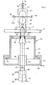
- FIG. 4 shows, partially in section, a preferred embodiment of a drill head 63, together with the arrangement of the plunger piston 49 and templates 53.
- the drill head 63 is mounted on a base plate 65, on which a drive, for example an electric motor 67, is arranged.
- the rotor of the electric motor 67 is extended as a drive axis 69 for a driver head 71.
- This is frustoconical, the frustum of the cone pointing towards the rods 5 and 7, respectively.
- an inner cylinder 77 slides like a piston with a lower protruding end ring 79.
- the end ring 75 of the outer cylinder 73 thus acts as a stop for the ring 79 and thus the inner cylinder 77.
- a clamping ring 81 is arranged at its upper end in the area of the driving head 71, the inner opening of which also has conical clamping surfaces 83, at most covered with an elastic, well-adhering material.
- the drive axle 69 is, as shown at 85, mounted in the motor 67 so as to be longitudinally displaceable.
- the axis 69 extends through the motor 67 and is rotatably connected to a bearing 87 on the piston 89 of a pneumatic or hydraulic piston / cylinder arrangement with cylinder 91 and control lines 93 and 95.
- the template 53 with the wire segment cut into the segment by means of the scissors 59 is first lowered over the plunger piston 49, then the latter is withdrawn and the template 53 is moved further over the rods 5 and 7 to be connected, the ends of the clips 61 protrude into the center opening of the clamping ring 81 a.
- the piston 89 and thus the drive axle 69 with the driver head 71 is raised via the control line 93, with the result that the template ends projecting from the cone driver ends 71 are clamped between the conical driver head 71 and the clamping surface 83.
- the motor 67 is started, whereby the drive axle 69, the head 71 and, via the clamp seat, the clasp ends and the clamping ring 81 rotate.
- the templates 53a and 5b show a side view of a preferred embodiment of the template 53 and a sectional view along line V - V of FIG. 5a.
- the templates 53a are formed from a plate, in which a U-shaped indentation 99 is incorporated.
- the plate 97 is connected to the bearing axis 57.
- projecting collars 103 are provided on the leg portions 101 of the plate 97 formed by the indentation 99 in such a way that a guide and mounting groove 105 for the agraffes arises.
- the ends of the leg parts 101, as shown in Fig. 5b are visible, notched at 107 so that guides are formed, into which the B supported indedrahtsegment.
- a receiving mold 109 is provided, if necessary, which allows the clamping cam 51 of the associated plunger piston 49 to be received when the template 53 is lowered onto the piston, and which further retracts this piston 49 in the direction indicated in Fig. 5b.
- the various work movements explained with reference to FIGS. 2, 3 and 4 are driven in a known manner, for example hydraulically or pneumatically. Furthermore, the positioning of the entire binding bench 23a or b according to FIG. 1 transversely to the longitudinal bar direction is preferably adjustable.
- the drilling heads 63 arranged below the level E 5 according to FIG. 2 and the organs arranged above them with stamping pistons 49, templates 53, carriages 35, clamping tongs 47 and guide or drive rollers 45 form a jointly displaceable working unit, as already shown in FIG. 1 shown.
- FIGS. 6 and 7 show the feed mechanism for the bars in the binding benches 23 according to FIG. 1 or on the longitudinal bar bench 15. Although subsequently described for feeding the crossbars 7, the mechanism shown can also be used without difficulty for feeding the longitudinal bars 5 from the crane 13 into the guides 17.
- FIG. 6 shows a cross-section of a binding bench 23 in analogy to FIGS. 2, 3, now with the feed device for the cross bars 7.
- the overhead crane 25 shown schematically with the crane truck 27 can be pivoted in the direction of 8 s on the bridge 26 S 4 slidably mounted.
- the carriage 27 is trough-shaped, the trough bottom having a part 113 which can be folded down and controlled by a hinge 111. By pivoting the base part 113 downward, the cross bars 7 mounted in the crane truck 27 are fed to the magazine and feed device on the binding bench 23.
- a plurality of driven rollers 117 are provided on the bar 55 according to FIG. 3, on which the templates 53 are mounted and on which the scissors 59 are fixed.
- the cross bars 7 delivered by the crane truck 27 now initially fall into the loose conveyor belts 119, whereupon, by driving the rollers 117 - in the direction of rotation shown, the conveyor belts 119 are shortened. As a result, the cross bars 7 stored therein are raised, as shown, and roll into the feed channel 121.
- a first pawl arrangement 123 protruding into the feed channel 121 for example pneumatically operated, initially closes the further passage of the feed channel 121.
- a second pawl arrangement 125 for example also pneumatically operated, is provided, so that by withdrawing the first latch assembly 123 a cross bar 7 is dropped onto the still locking second latch arrangement 125, the retraction of which only releases the corresponding cross bar 7 for further falling onto the longitudinal bars 5.
- the upper pawl arrangement 123 has the task of absorbing the weight of the cross bars 7 resting on one another, so that the release of individual cross bars 7 by the second pawl arrangement 125 can thereby take place without being influenced.
- the corresponding cross bar 7 is guided between a plurality of pairs of guide rods 127, one behind the other in the cross bar direction, onto the longitudinal bars 5 and held in position there.
- the pairs of guide rods are arranged between the stencils / stamps / drill head arrangements which follow one another in the transverse rod direction and thus do not impair their functioning.
- the guide rod at the front in the feed direction can be resiliently pivoted at 130.
- FIG. 7a and 7b show a preferred embodiment of the double latch arrangement 123 and 125 according to FIG. 6.
- the two pawls are formed by two circular segments 129 and 131, which are driven together about an axis 133.
- the two segments are offset in the axial direction, likewise by an angle of rotation P.
- the segment 131 closes the crossbar passage to the guide rod pairs 127.
- the segment arrangement rotates in the direction designated by x 7b, the lower segment 131 is increasingly pivoted out of the area of the crossbar 7 lying thereon and more and more releases the passage to the guide rod pairs 127.
- the upper segment 129 engages more and more between the crossbar 7 lying directly on the segment 131 and the next one, until the segment 131 finally clears the passage for the immediately lying crossbar 7, whereas the segment 129 blocks the passage for the next one . If the segment arrangement is now turned back in the opposite direction, the crossbar which was previously held open by segment 129 falls on the lower segment 131, which in turn blocks the passage, so that a renewed reversal of the direction of rotation, corresponding to x from FIG. 7b, again releases the direct causes crossbar 7 resting on segment 131, with simultaneous blocking of the passage for the next following crossbar by upper segment 129.
- the longitudinal rods 5 in order to then be connected to the latter.
- the upper segment 129 can be attached to a ring -134, the internal thread 136 of which runs on the external thread of the axis 133 and which can be locked by means of clamping screws 138.
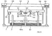
- Fig. 8 is a side view of a preferred embodiment of the overhead crane 9 in the storage zone 1 is shown, with the help of the longitudinal and cross bars 5, 7 are lifted from the corresponding storage areas and, as shown in Fig. 1, the cross bar crane 25 or the longitudinal bar crane 13 are funded.
- the overhead crane 9 comprises an upper bridge 137, running on schematically illustrated rails 135, on which a lifting bridge 141 is mounted on rails 139, which can be raised or lowered vertically.
- the lifting bridge 141 is lowered into the bearing sections shown in FIG. 1 between the bearing posts 3 for receiving the rods stored there.
- the inclusion of the rod material is not entirely unproblematic in that it must be prevented that individual rods, which in some cases are thick and thus heavy, fall back after being lifted.
- an electromagnet 143 is provided approximately in the middle of the lifting bridge 141. If the lifting bridge 141 is lowered onto the rods 5 and 7, the electromagnet 143 is activated and, as indicated by dashed lines in FIG. 8, attracts a number of rods. Viewed in the longitudinal direction of the lifting bridge 141, on both sides of the electromagnet 143, mounted longitudinally displaceably along the bridge 141, lower gripping arms 145 provided, with a first arm 147 projecting vertically downwards and a second arm from a vertical position, on a hinge part 149, driven arm 151 pivotable into a horizontal position.
- the arms 151 are driven, placed horizontally, and, as shown in dashed lines at 151a, reach under the bars held on the magnet.
- the lower gripping arms 145 are then moved outwards, preferably with arms 151 designed as rollers, as indicated by arrows in the figure, and lift the bent side parts of the rods into the extended position. This ensures secure guidance and support for the rods received.
- the lifting bridge 141 is raised further, and with a feed mechanism, shown schematically at 153, the received bars are fed to a drive and cutting device 155, where they are cut to the correct length, then, as shown in FIG. 1, to the overhead traveling cranes 13 or 27 are pushed shut.
- the other units of the overall system shown in Fig. 1 are constructed in a known manner.
- the distribution of the longitudinal bars 5 from the overhead crane 13 to the longitudinal bar bed 15 can be carried out as described for the delivery of the transverse bars to the binding benches 23 in connection with FIG. 6.
- the entire system is preferably controlled fully automatically, for which a computer or microprocessor control is particularly suitable.
- a computer or microprocessor control is particularly suitable.
- the mesh size of the net 33 produced can be chosen to be as narrow as desired, whereby it should be ensured that the tying points lying in the longitudinal as well as in the transverse direction follow the crosshairs diagonally offset by 90 °. This also applies if only every second crossing section is tied, which in most cases allows the setting strength to be achieved without further ado.
Applications Claiming Priority (2)
| Application Number | Priority Date | Filing Date | Title |
|---|---|---|---|
| CH2021/83 | 1983-04-15 | ||
| CH202183 | 1983-04-15 |
Publications (2)
| Publication Number | Publication Date |
|---|---|
| EP0122883A2 true EP0122883A2 (fr) | 1984-10-24 |
| EP0122883A3 EP0122883A3 (fr) | 1987-06-03 |
Family
ID=4224054
Family Applications (1)
| Application Number | Title | Priority Date | Filing Date |
|---|---|---|---|
| EP84810183A Withdrawn EP0122883A3 (fr) | 1983-04-15 | 1984-04-13 | Procédé d'assemblage mécanique des barres d'un treillis et appareil d'assemblage mécanique des barres d'un treillis |
Country Status (1)
| Country | Link |
|---|---|
| EP (1) | EP0122883A3 (fr) |
Cited By (6)
| Publication number | Priority date | Publication date | Assignee | Title |
|---|---|---|---|---|
| WO2004009266A1 (fr) * | 2002-07-23 | 2004-01-29 | Stema Engineering A/S | Procede et appareil de fabrication de treillis de tiges d'armature de beton |
| WO2007110400A1 (fr) * | 2006-03-28 | 2007-10-04 | Beta Systems Srl | dispositif d'accumulation et d'injection pour barres de métal |
| JP2013035052A (ja) * | 2011-08-10 | 2013-02-21 | Teibyou:Kk | 鉄筋網の製造方法と、その装置 |
| WO2018122132A1 (fr) * | 2016-12-29 | 2018-07-05 | M.E.P. Macchine Elettroniche Piegatrici S.P.A. | Appareil et procédé de manutention de barres |
| US10926315B2 (en) | 2014-04-01 | 2021-02-23 | Antonios Anagnostopoulos | Systems and processes for feeding longitudinal wires or rods to mesh producing machines |
| WO2022073695A1 (fr) * | 2020-10-09 | 2022-04-14 | Bam Ag | Machine et procédé de production de treillis métalliques en fils d'acier simplement renforcés |
Citations (5)
| Publication number | Priority date | Publication date | Assignee | Title |
|---|---|---|---|---|
| US1437488A (en) * | 1914-06-06 | 1922-12-05 | Blashill Wire Machinery Compan | Wire-fabric machine |
| US3169559A (en) * | 1961-03-02 | 1965-02-16 | Jr Loren F Working | Wire tying tool |
| US4068110A (en) * | 1975-03-25 | 1978-01-10 | Elektriska Svetsningsaktiebolaget | Method and apparatus for the manufacture of welded gratings |
| US4096680A (en) * | 1976-05-07 | 1978-06-27 | Firma Avi Alpenlandische Veredelungs- Industrie Gesellschaft Mbh. | Reinforcement grid for steel concrete construction |
| AT363765B (de) * | 1976-04-28 | 1981-08-25 | Avi Alpenlaendische Vered | Werkzeug zum verroedeln von gekreuzten staeben und mit solchen werkzeugen ausgestattete maschine zum herstellen eines bewehrungsgitters |
-
1984
- 1984-04-13 EP EP84810183A patent/EP0122883A3/fr not_active Withdrawn
Patent Citations (5)
| Publication number | Priority date | Publication date | Assignee | Title |
|---|---|---|---|---|
| US1437488A (en) * | 1914-06-06 | 1922-12-05 | Blashill Wire Machinery Compan | Wire-fabric machine |
| US3169559A (en) * | 1961-03-02 | 1965-02-16 | Jr Loren F Working | Wire tying tool |
| US4068110A (en) * | 1975-03-25 | 1978-01-10 | Elektriska Svetsningsaktiebolaget | Method and apparatus for the manufacture of welded gratings |
| AT363765B (de) * | 1976-04-28 | 1981-08-25 | Avi Alpenlaendische Vered | Werkzeug zum verroedeln von gekreuzten staeben und mit solchen werkzeugen ausgestattete maschine zum herstellen eines bewehrungsgitters |
| US4096680A (en) * | 1976-05-07 | 1978-06-27 | Firma Avi Alpenlandische Veredelungs- Industrie Gesellschaft Mbh. | Reinforcement grid for steel concrete construction |
Cited By (12)
| Publication number | Priority date | Publication date | Assignee | Title |
|---|---|---|---|---|
| WO2004009266A1 (fr) * | 2002-07-23 | 2004-01-29 | Stema Engineering A/S | Procede et appareil de fabrication de treillis de tiges d'armature de beton |
| WO2007110400A1 (fr) * | 2006-03-28 | 2007-10-04 | Beta Systems Srl | dispositif d'accumulation et d'injection pour barres de métal |
| JP2013035052A (ja) * | 2011-08-10 | 2013-02-21 | Teibyou:Kk | 鉄筋網の製造方法と、その装置 |
| US10926315B2 (en) | 2014-04-01 | 2021-02-23 | Antonios Anagnostopoulos | Systems and processes for feeding longitudinal wires or rods to mesh producing machines |
| WO2018122132A1 (fr) * | 2016-12-29 | 2018-07-05 | M.E.P. Macchine Elettroniche Piegatrici S.P.A. | Appareil et procédé de manutention de barres |
| CN110392612A (zh) * | 2016-12-29 | 2019-10-29 | Mep意大利美普机械制造有限公司 | 用于处理杆的设备和方法 |
| EP3562605B1 (fr) | 2016-12-29 | 2021-01-20 | M.E.P. Macchine Elettroniche Piegatrici S.p.A. | Appareil et procédé de manutention de barres |
| CN110392612B (zh) * | 2016-12-29 | 2021-11-26 | Mep意大利美普机械制造有限公司 | 用于处理杆的设备和方法 |
| AU2017385520B2 (en) * | 2016-12-29 | 2023-02-23 | M.E.P. Macchine Elettroniche Piegatrici S.P.A. | Apparatus and method for handling bars |
| US11648603B2 (en) | 2016-12-29 | 2023-05-16 | M.E.P. Macchine Elettroniche Piegatrici S.P.A. | Apparatus and method for handling bars |
| WO2022073695A1 (fr) * | 2020-10-09 | 2022-04-14 | Bam Ag | Machine et procédé de production de treillis métalliques en fils d'acier simplement renforcés |
| AU2021358290B2 (en) * | 2020-10-09 | 2023-08-10 | Bam Ag | Machine and method for producing simply reinforced steel wire meshes |
Also Published As
| Publication number | Publication date |
|---|---|
| EP0122883A3 (fr) | 1987-06-03 |
Similar Documents
| Publication | Publication Date | Title |
|---|---|---|
| EP2035283A1 (fr) | Dispositif de traitement de structures tubulaires souples présentant au moins une ouverture | |
| WO1991004113A1 (fr) | Dispositif de pliage de barres en acier afin de façonner des elements d'armatures en beton | |
| DE2909121A1 (de) | Einer mangel vorschaltbare eingabemaschine | |
| DE2420690A1 (de) | Vorrichtung zum biegen von rohrabschnitten | |
| DE3202233A1 (de) | Vorrichtung zum umschnueren von ballen | |
| AT406556B (de) | Verfahren und vorrichtung zur vereinzelung und weiterbearbeitung von metallstäben | |
| EP0122883A2 (fr) | Procédé d'assemblage mécanique des barres d'un treillis et appareil d'assemblage mécanique des barres d'un treillis | |
| DE2105163A1 (de) | Maschine zum Pressen und Umschnüren von Ballen mit Draht | |
| DE1586913B1 (de) | Verfahren und Vorrichtung zum Herstellen einer Bandschleife und zum Anlegen derselben um einen Gegenstand herum | |
| DE3314054A1 (de) | Verfahren zum maschinellen binden von armierungsnetzen sowie anordnung zur ausfuehrung des verfahrens | |
| DE2142321A1 (de) | Verfahren und vorrichtung zum herstellen von gitterrostmatten | |
| DE102019107073B4 (de) | Vorrichtung und verfahren zum automatisierten abbinden von kabeln | |
| AT502466B1 (de) | Verfahren und schweissmaschine zum herstellen von gitterprodukten | |
| AT408196B (de) | Verfahren und anlage zum herstellen von gittermatten | |
| DE69821760T2 (de) | Vorrichtung zum Herstellen von Ringwickeln aus langgestrecktem Gut | |
| EP1101869A1 (fr) | Installation de manutention de traverses de chemin de fer | |
| DE1929788A1 (de) | Gitterschweissmaschine | |
| DE1297528B (de) | Vorrichtung zum Pressen und Binden von gruppenweise koaxial nebeneinander gelegten Walzdrahtbunden | |
| WO1993021366A1 (fr) | Procede et dispositif permettant de changer plus aisement une chaine | |
| DE1786101A1 (de) | Spannvorrichtung | |
| DE2725511A1 (de) | Einrichtung zur verstaerkung eines spulendrahtabschnittes | |
| DE3204563C1 (de) | Verfahren und Vorrichtung zum Herstellen von räumlichen Gitterträgern | |
| CH681900A5 (fr) | ||
| DE2001358B2 (fr) | ||
| DE1402865A1 (de) | Verfahren zum Einfuehren von Draehten oder Staeben in eine Reck- und/oder Drillvorrichtung,insbesondere fuer Betonrippenstaehle sowie Vorrichtung zum Durchfuehren des Verfahrens |
Legal Events
| Date | Code | Title | Description |
|---|---|---|---|
| PUAI | Public reference made under article 153(3) epc to a published international application that has entered the european phase |
Free format text: ORIGINAL CODE: 0009012 |
|
| AK | Designated contracting states |
Designated state(s): AT BE CH DE FR GB IT LI LU NL SE |
|
| 17P | Request for examination filed |
Effective date: 19841102 |
|
| PUAL | Search report despatched |
Free format text: ORIGINAL CODE: 0009013 |
|
| AK | Designated contracting states |
Kind code of ref document: A3 Designated state(s): AT BE CH DE FR GB IT LI LU NL SE |
|
| STAA | Information on the status of an ep patent application or granted ep patent |
Free format text: STATUS: THE APPLICATION IS DEEMED TO BE WITHDRAWN |
|
| 18D | Application deemed to be withdrawn |
Effective date: 19871101 |
|
| RIN1 | Information on inventor provided before grant (corrected) |
Inventor name: DER ERFINDER HAT AUF SEINE NENNUNG VERZICHTET. |