EP0122883A2 - Method of mechanically connecting the rods of a rod network, and apparatus for mechanically connecting the rods of a rod network - Google Patents
Method of mechanically connecting the rods of a rod network, and apparatus for mechanically connecting the rods of a rod network Download PDFInfo
- Publication number
- EP0122883A2 EP0122883A2 EP84810183A EP84810183A EP0122883A2 EP 0122883 A2 EP0122883 A2 EP 0122883A2 EP 84810183 A EP84810183 A EP 84810183A EP 84810183 A EP84810183 A EP 84810183A EP 0122883 A2 EP0122883 A2 EP 0122883A2
- Authority
- EP
- European Patent Office
- Prior art keywords
- binding element
- preferably according
- rods
- rod
- templates
- Prior art date
- Legal status (The legal status is an assumption and is not a legal conclusion. Google has not performed a legal analysis and makes no representation as to the accuracy of the status listed.)
- Withdrawn
Links
Images


Classifications
-
- B—PERFORMING OPERATIONS; TRANSPORTING
- B21—MECHANICAL METAL-WORKING WITHOUT ESSENTIALLY REMOVING MATERIAL; PUNCHING METAL
- B21F—WORKING OR PROCESSING OF METAL WIRE
- B21F23/00—Feeding wire in wire-working machines or apparatus
- B21F23/005—Feeding discrete lengths of wire or rod
-
- B—PERFORMING OPERATIONS; TRANSPORTING
- B21—MECHANICAL METAL-WORKING WITHOUT ESSENTIALLY REMOVING MATERIAL; PUNCHING METAL
- B21F—WORKING OR PROCESSING OF METAL WIRE
- B21F27/00—Making wire network, i.e. wire nets
- B21F27/08—Making wire network, i.e. wire nets with additional connecting elements or material at crossings
-
- E—FIXED CONSTRUCTIONS
- E04—BUILDING
- E04C—STRUCTURAL ELEMENTS; BUILDING MATERIALS
- E04C5/00—Reinforcing elements, e.g. for concrete; Auxiliary elements therefor
- E04C5/01—Reinforcing elements of metal, e.g. with non-structural coatings
- E04C5/02—Reinforcing elements of metal, e.g. with non-structural coatings of low bending resistance
- E04C5/04—Mats
Definitions
- the present invention relates to a method for mechanically connecting the rods of a rod network, in which a wire-shaped binding element is fed to an intersection, fixed there and a segment is separated therefrom and the connection is established with the latter, and a system for mechanically connecting the rods of a rod network to a feed arrangement for a wire-shaped binding element, fixing elements and severing elements for the binding element in the area of a rod crossing point as well as with connecting elements in crossing point areas for the rod connection by means of separated binding element segments.
- a method of the type mentioned is known from AT-PS 363 765.
- Two tie wires are fed to each crossing point of the reinforcing mesh longitudinal and transverse bars, by pulling the ends of these away from the corresponding supplies and specifically feeding these ends to each crossing point.
- This means that the binding wire ends must be selectively fed to each of a multiplicity of crossing points to be connected, and that two ent for each of the crossing points to be connected simultaneously speaking supply devices for the element must be provided.
- a terminal section is cut off from each of the two binding wire ends fed to each crossing point, bent agraff-shaped, placed over the assigned crossing point and finally twisted in a rod-connecting manner.
- the primary disadvantage of this technology is that the end of a binding wire is fed to each crossing point, with the resulting complexity of a system which simultaneously executes the known method at a large number of crossing points.
- the aim of the present invention is to further develop the above-mentioned method in such a way that the binding wire feed is considerably simplified.
- the feed device comprises a feed carriage which is driven through a plurality of intersection areas and which, with gripping members for the wire-shaped binding element, runs the latter over a plurality of intersection areas.
- the system according to the invention only makes it possible to create a system by means of appropriate further development according to the invention which can quickly, practically in continuous operation, tie large-area networks.
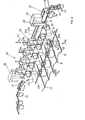
- Fig. 1 the manufacturing plant is shown schematically in supervision.
- a storage zone 1 longitudinal bars 5 or transverse bars 7 to be processed are stacked between rows of bearing posts 3 which project vertically on the floor.
- a traveling crane 9 is arranged above the storage zone 1, with the aid of which longitudinal rods 5 or transverse rods 7 are raised in a manner to be described.
- the longitudinal rods 5 After the longitudinal rods 5 have been lifted, they are first cut to the desired length by means of cutting elements on the overhead crane 9, then conveyed onto a longitudinal rod overhead crane 13 by means of a roller feed mechanism 11. After the longitudinal rods 5 have been taken over by the overhead crane 9, the longitudinal rod overhead crane 13 moves in the direction indicated by S 1 over a longitudinal rod bed 15 of the production system.
- the longitudinal bar bed 15 is formed in cross-section like a corrugated sheet, with guide grooves 17, in which the longitudinal bar overhead crane 13 distributes the longitudinal bars 5.
- a rake-like feed arrangement 19 pushes the longitudinal rods 5 deposited in the guide channels 17 in the direction indicated by S 2 against the production zone 21.
- two binding banks 23a and 23b are arranged.
- a cross bar overhead crane 25 is provided on a level higher with respect to the longitudinal bar overhead traveling crane 13 on its running rails 13a, 13b.
- a cross bar overhead crane 25 is provided on the one hand, it is displaceable on rails 25a, 25b parallel to the guide channels 17 of the longitudinal rod bed 15, as indicated by S 3 , and comprises a crane truck 27 which is displaceable in the direction indicated by S 4 on the bridge 26 which can be displaced in the direction S 3 , and which, as shown by S 5 , is also pivotable about a vertical axis 29.
- the cross bars 7 are raised in an analogous manner to the longitudinal bars 5, cut to the correct length if necessary, and conveyed to the crane truck 27 in the position shown with the roller feed mechanism 11.
- the longitudinal rods 5 advanced in saccades are connected to the transverse rods 7 deposited there by pulling binding wire out of binding wire stocks 31, as will be described later, into agraffes, preferably from above the crossing points of cross and longitudinal bars 7, 5 are placed and then twisted below.
- the cross bars 7 on the longitudinal bars 5 feeding the clasps from above, twisting their ends at the bottom, there are twisted braids which project downward from the longitudinal bars. In practice, this is of great advantage because when the net profiles are subsequently formed, by bending the net in the longitudinal direction of the rod, these braids come to the inside.
- two production banks 23 staggered on the side can be used to increase the production speed or if relatively dense reinforcement nets 33 are to be produced.
- individual binding benches or more than two can also be provided if necessary.
- FIGS. 2, 3, 4 and 5 the structure and the mode of operation of the binding benches 23 according to FIG. 1, as far as the actual setting is concerned, is shown.
- FIG. 2 the basic structure of such a bank is shown in perspective.
- the longitudinal rods 5 are fed to the binding bench 23 on the longitudinal rod bed 15.
- the cross bars 7 are also placed sequentially over the longitudinal bars 5 here.
- Each binding bench 23 comprises a binding wire feed carriage 35. It runs on a guide 37 fixed to the frame, transverse to the longitudinal bars 5, over the entire width of the longitudinal bar bed 15 and, as not shown for reasons of clarity, is, for example, chain-driven.
- the binding wire 43 is motor-driven by a bearing spool, not shown here, via a plurality of guide and drive rollers 45, further by a controllable clamping pliers 47, which are then fed to the open holding pliers 41 of the gripping arm 39. The pliers 41 are then closed and the binding wire 43 is clamped therein.
- the binding wire feed carriage 35 is moved over the entire width of the bed 15 and pulls the binding wire 43, as shown at 43a, over this width, i.e. over all longitudinal rods 5.
- the carriage 35 has reached the other side position, as indicated by dashed lines in FIG. 2, it is locked, the pliers 41 still holding the binding wire end clamped.
- a number, preferably pneumatically or hydraulically actuated, plunger pistons 49 are provided, which can be retracted or extended parallel to the longitudinal bars 5, as indicated by S 6 , with respect to the frame part 38 also carrying the guide 37 .
- the axes of the plunger pistons 49 are aligned with guide channels 17 in the bed 15.
- the pistons 49 at least the peripheral ones, have a tensioning cam 51 on their upper side, the gripping arm 39 of the carriage 35 pulling the wire 43 through directly in front of the tensioning cam 51.
- the clamping pliers 47 are closed and fix the wire 43.
- the plunger pistons 49 are driven into the position shown in broken lines. This results, as also shown in dash-dotted lines at 43b, in a tensioning of the binding wire, wherein it is pressed parallel to the plane E spanned by the longitudinal rods 5 and parallel to the transverse rods 7 from position 43a to position 43b. This brings him into the area of the actual binding devices, which will now be described below.
- the binding wire now lies exactly above the inserted cross bar 7.
- U-shaped templates 53 are arranged above the inserted cross bar 7 in such a way that on the one hand their u-legs lie directly above the binding wire in position 43b and on the other hand the template plane E 53 is perpendicular to plane E 5 .
- the stencils 53, on the one hand, as shown with S - are mounted such that they can move up and down perpendicularly to the plane E 5 , for example on a bar 55 according to FIG. 3, and they also, as with S 8 shown about their bearing axes 57 are pivotable.
- the templates 53 are all lowered together until, as indicated by dash-dotted lines at 53a, the wire 43 is clamped between the intended plunger 49 and the legs of the templates 53, midway between the templates 53 stationary scissors 59, shown schematically in Fig. 3, the wire is now cut into individual segments. These each remain fixed between two template legs and the assigned stamp 49.
- the templates 53 are then lowered together via the plunger pistons 49 assigned to them, with which the wire segments are bent into U-shaped clips 61.
- the inherent elasticity of the wire reinforced by the tensioning process, as well as the shape of the inner surface of the template, which will be described with reference to FIG.
- FIG. 3 shows a simplified view from below of the arrangement of FIG. 2, in particular to clarify the arrangement of the scissors 59. Furthermore, it can be seen from this that there may be circumstances it is necessary to provide auxiliary clamping pistons 50 at the edge, in analogy to the plunger pistons 49, which probably do not interact with any of the templates 53, but ensure that the binding wire course in the front position according to 43b is not angled even under the peripheral templates 53 and the peripheral scissors 59, but still runs transversely to the longitudinal bars 5.
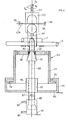
- FIG. 4 shows, partially in section, a preferred embodiment of a drill head 63, together with the arrangement of the plunger piston 49 and templates 53.
- the drill head 63 is mounted on a base plate 65, on which a drive, for example an electric motor 67, is arranged.
- the rotor of the electric motor 67 is extended as a drive axis 69 for a driver head 71.
- This is frustoconical, the frustum of the cone pointing towards the rods 5 and 7, respectively.
- an inner cylinder 77 slides like a piston with a lower protruding end ring 79.
- the end ring 75 of the outer cylinder 73 thus acts as a stop for the ring 79 and thus the inner cylinder 77.
- a clamping ring 81 is arranged at its upper end in the area of the driving head 71, the inner opening of which also has conical clamping surfaces 83, at most covered with an elastic, well-adhering material.
- the drive axle 69 is, as shown at 85, mounted in the motor 67 so as to be longitudinally displaceable.
- the axis 69 extends through the motor 67 and is rotatably connected to a bearing 87 on the piston 89 of a pneumatic or hydraulic piston / cylinder arrangement with cylinder 91 and control lines 93 and 95.
- the template 53 with the wire segment cut into the segment by means of the scissors 59 is first lowered over the plunger piston 49, then the latter is withdrawn and the template 53 is moved further over the rods 5 and 7 to be connected, the ends of the clips 61 protrude into the center opening of the clamping ring 81 a.
- the piston 89 and thus the drive axle 69 with the driver head 71 is raised via the control line 93, with the result that the template ends projecting from the cone driver ends 71 are clamped between the conical driver head 71 and the clamping surface 83.
- the motor 67 is started, whereby the drive axle 69, the head 71 and, via the clamp seat, the clasp ends and the clamping ring 81 rotate.
- the templates 53a and 5b show a side view of a preferred embodiment of the template 53 and a sectional view along line V - V of FIG. 5a.
- the templates 53a are formed from a plate, in which a U-shaped indentation 99 is incorporated.
- the plate 97 is connected to the bearing axis 57.
- projecting collars 103 are provided on the leg portions 101 of the plate 97 formed by the indentation 99 in such a way that a guide and mounting groove 105 for the agraffes arises.
- the ends of the leg parts 101, as shown in Fig. 5b are visible, notched at 107 so that guides are formed, into which the B supported indedrahtsegment.
- a receiving mold 109 is provided, if necessary, which allows the clamping cam 51 of the associated plunger piston 49 to be received when the template 53 is lowered onto the piston, and which further retracts this piston 49 in the direction indicated in Fig. 5b.
- the various work movements explained with reference to FIGS. 2, 3 and 4 are driven in a known manner, for example hydraulically or pneumatically. Furthermore, the positioning of the entire binding bench 23a or b according to FIG. 1 transversely to the longitudinal bar direction is preferably adjustable.
- the drilling heads 63 arranged below the level E 5 according to FIG. 2 and the organs arranged above them with stamping pistons 49, templates 53, carriages 35, clamping tongs 47 and guide or drive rollers 45 form a jointly displaceable working unit, as already shown in FIG. 1 shown.
- FIGS. 6 and 7 show the feed mechanism for the bars in the binding benches 23 according to FIG. 1 or on the longitudinal bar bench 15. Although subsequently described for feeding the crossbars 7, the mechanism shown can also be used without difficulty for feeding the longitudinal bars 5 from the crane 13 into the guides 17.
- FIG. 6 shows a cross-section of a binding bench 23 in analogy to FIGS. 2, 3, now with the feed device for the cross bars 7.
- the overhead crane 25 shown schematically with the crane truck 27 can be pivoted in the direction of 8 s on the bridge 26 S 4 slidably mounted.
- the carriage 27 is trough-shaped, the trough bottom having a part 113 which can be folded down and controlled by a hinge 111. By pivoting the base part 113 downward, the cross bars 7 mounted in the crane truck 27 are fed to the magazine and feed device on the binding bench 23.
- a plurality of driven rollers 117 are provided on the bar 55 according to FIG. 3, on which the templates 53 are mounted and on which the scissors 59 are fixed.
- the cross bars 7 delivered by the crane truck 27 now initially fall into the loose conveyor belts 119, whereupon, by driving the rollers 117 - in the direction of rotation shown, the conveyor belts 119 are shortened. As a result, the cross bars 7 stored therein are raised, as shown, and roll into the feed channel 121.
- a first pawl arrangement 123 protruding into the feed channel 121 for example pneumatically operated, initially closes the further passage of the feed channel 121.
- a second pawl arrangement 125 for example also pneumatically operated, is provided, so that by withdrawing the first latch assembly 123 a cross bar 7 is dropped onto the still locking second latch arrangement 125, the retraction of which only releases the corresponding cross bar 7 for further falling onto the longitudinal bars 5.
- the upper pawl arrangement 123 has the task of absorbing the weight of the cross bars 7 resting on one another, so that the release of individual cross bars 7 by the second pawl arrangement 125 can thereby take place without being influenced.
- the corresponding cross bar 7 is guided between a plurality of pairs of guide rods 127, one behind the other in the cross bar direction, onto the longitudinal bars 5 and held in position there.
- the pairs of guide rods are arranged between the stencils / stamps / drill head arrangements which follow one another in the transverse rod direction and thus do not impair their functioning.
- the guide rod at the front in the feed direction can be resiliently pivoted at 130.
- FIG. 7a and 7b show a preferred embodiment of the double latch arrangement 123 and 125 according to FIG. 6.
- the two pawls are formed by two circular segments 129 and 131, which are driven together about an axis 133.
- the two segments are offset in the axial direction, likewise by an angle of rotation P.
- the segment 131 closes the crossbar passage to the guide rod pairs 127.
- the segment arrangement rotates in the direction designated by x 7b, the lower segment 131 is increasingly pivoted out of the area of the crossbar 7 lying thereon and more and more releases the passage to the guide rod pairs 127.
- the upper segment 129 engages more and more between the crossbar 7 lying directly on the segment 131 and the next one, until the segment 131 finally clears the passage for the immediately lying crossbar 7, whereas the segment 129 blocks the passage for the next one . If the segment arrangement is now turned back in the opposite direction, the crossbar which was previously held open by segment 129 falls on the lower segment 131, which in turn blocks the passage, so that a renewed reversal of the direction of rotation, corresponding to x from FIG. 7b, again releases the direct causes crossbar 7 resting on segment 131, with simultaneous blocking of the passage for the next following crossbar by upper segment 129.
- the longitudinal rods 5 in order to then be connected to the latter.
- the upper segment 129 can be attached to a ring -134, the internal thread 136 of which runs on the external thread of the axis 133 and which can be locked by means of clamping screws 138.
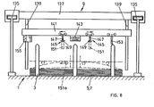
- Fig. 8 is a side view of a preferred embodiment of the overhead crane 9 in the storage zone 1 is shown, with the help of the longitudinal and cross bars 5, 7 are lifted from the corresponding storage areas and, as shown in Fig. 1, the cross bar crane 25 or the longitudinal bar crane 13 are funded.
- the overhead crane 9 comprises an upper bridge 137, running on schematically illustrated rails 135, on which a lifting bridge 141 is mounted on rails 139, which can be raised or lowered vertically.
- the lifting bridge 141 is lowered into the bearing sections shown in FIG. 1 between the bearing posts 3 for receiving the rods stored there.
- the inclusion of the rod material is not entirely unproblematic in that it must be prevented that individual rods, which in some cases are thick and thus heavy, fall back after being lifted.
- an electromagnet 143 is provided approximately in the middle of the lifting bridge 141. If the lifting bridge 141 is lowered onto the rods 5 and 7, the electromagnet 143 is activated and, as indicated by dashed lines in FIG. 8, attracts a number of rods. Viewed in the longitudinal direction of the lifting bridge 141, on both sides of the electromagnet 143, mounted longitudinally displaceably along the bridge 141, lower gripping arms 145 provided, with a first arm 147 projecting vertically downwards and a second arm from a vertical position, on a hinge part 149, driven arm 151 pivotable into a horizontal position.
- the arms 151 are driven, placed horizontally, and, as shown in dashed lines at 151a, reach under the bars held on the magnet.
- the lower gripping arms 145 are then moved outwards, preferably with arms 151 designed as rollers, as indicated by arrows in the figure, and lift the bent side parts of the rods into the extended position. This ensures secure guidance and support for the rods received.
- the lifting bridge 141 is raised further, and with a feed mechanism, shown schematically at 153, the received bars are fed to a drive and cutting device 155, where they are cut to the correct length, then, as shown in FIG. 1, to the overhead traveling cranes 13 or 27 are pushed shut.
- the other units of the overall system shown in Fig. 1 are constructed in a known manner.
- the distribution of the longitudinal bars 5 from the overhead crane 13 to the longitudinal bar bed 15 can be carried out as described for the delivery of the transverse bars to the binding benches 23 in connection with FIG. 6.
- the entire system is preferably controlled fully automatically, for which a computer or microprocessor control is particularly suitable.
- a computer or microprocessor control is particularly suitable.
- the mesh size of the net 33 produced can be chosen to be as narrow as desired, whereby it should be ensured that the tying points lying in the longitudinal as well as in the transverse direction follow the crosshairs diagonally offset by 90 °. This also applies if only every second crossing section is tied, which in most cases allows the setting strength to be achieved without further ado.
Landscapes
- Engineering & Computer Science (AREA)
- Architecture (AREA)
- Mechanical Engineering (AREA)
- Civil Engineering (AREA)
- Structural Engineering (AREA)
- Wire Processing (AREA)
- Manufacturing Of Electrical Connectors (AREA)
Abstract
Description
Die vorliegende Erfindung betrifft ein Verfahren zum maschinellen Verbinden der Stäbe eines Stabnetzes, wobei man ein drahtförmiges Bindeelement einer Kreuzungsstelle zuspeist, dort fixiert und ein Segment davon abtrennt und mit letzterem die Verbindung erstellt sowie eine Anlage zum maschinellen Verbinden der Stäbe eines Stabnetzes mit einer Zuspeiseanordnung für ein drahtförmiges Bindeelement, Fixierorganen und Durchtrennorganen für das Bindeelement im Bereiche jeweils einer Stab-Kreuzungsstelle sowie mit Verbindorganen in Kreuzungsstellenbereichen für die Stabverbindung mittels abgetrennter Bindeelementsegmente.The present invention relates to a method for mechanically connecting the rods of a rod network, in which a wire-shaped binding element is fed to an intersection, fixed there and a segment is separated therefrom and the connection is established with the latter, and a system for mechanically connecting the rods of a rod network to a feed arrangement for a wire-shaped binding element, fixing elements and severing elements for the binding element in the area of a rod crossing point as well as with connecting elements in crossing point areas for the rod connection by means of separated binding element segments.
Aus der AT-PS 363 765 ist ein Verfahren eingangs genannter Art-bekannt. Jeder Kreuzungsstelle von Bewehrungsgitter-Längs- und Querstäben werden je zwei Bindedrähte zugeführt, indem diese mit ihren Enden von entsprechenden Vorräten abgezogen werden und diese Enden gezielt jeder Kreuzungsstelle zugeführt werden. Dies bedingt, dass jeder einer Vielzahl zu verbindender Kreuzungsstellen die besagten Bindedrahtenden selektiv zugeführt werden müssen und dass für jede der gleichzeitig zu verbindenden Kreuzungsstellen je zwei entsprechende Zuführeinrichtungen für das Element vorgesehen sein müssen. Von jedem der zwei jeder Kreuzungsstelle zugespiesenen Bindedrahtenden wird pro Arbeitstakt ein endständiger Abschnitt abgetrennt, agraffenförmig gebogen, über die zugeordnete Kreuzungsstelle gelegt und schliesslich stabverbindend verdrillt. Nachteilig an dieser Technologie ist primär, dass jeder Kreuzungsstelle das Ende eines Bindedrahtes zugeführt wird, mit der daraus folgenden Komplexität einer Anlage, die das bekannte Verfahren gleichzeitig an einer Vielzahl von Kreuzungsstellen ausführt.A method of the type mentioned is known from AT-PS 363 765. Two tie wires are fed to each crossing point of the reinforcing mesh longitudinal and transverse bars, by pulling the ends of these away from the corresponding supplies and specifically feeding these ends to each crossing point. This means that the binding wire ends must be selectively fed to each of a multiplicity of crossing points to be connected, and that two ent for each of the crossing points to be connected simultaneously speaking supply devices for the element must be provided. A terminal section is cut off from each of the two binding wire ends fed to each crossing point, bent agraff-shaped, placed over the assigned crossing point and finally twisted in a rod-connecting manner. The primary disadvantage of this technology is that the end of a binding wire is fed to each crossing point, with the resulting complexity of a system which simultaneously executes the known method at a large number of crossing points.
Die vorliegende Erfindung setzt sich nun zum Ziel, das eingangs genannte Verfahren derart weiter zu bilden, dass eine wesentliche Vereinfachung der Bindedrahtzuführung erzielt wird.The aim of the present invention is to further develop the above-mentioned method in such a way that the binding wire feed is considerably simplified.
Dies wird dadurch erreicht, dass man das Bindeelement über mehrere zu erstellende Kreuzungsstellen durchzieht und vom durchgezogenen Bindeelement Segmente im Bereich jeder der zu erstellenden Kreuzungsstellen fixiert und abschneidet.This is achieved by pulling the binding element over several intersection points to be created and fixing and cutting off segments from the solid binding element in the area of each of the crossing points to be created.
Die erfindungsgemässe Anlage löst die gestellte Aufgabe dadurch, dass die Zuspeiseeinrichtung einen über mehrere Kreuzungsstellenbereiche durchgetriebenen Einzugschlitten umfasst, der, mit Greiforganen für das drahtförmige Bindeelement, letzteres über mehrere Kreuzungsstellenbereiche durchzieht.The system according to the invention achieves the stated task in that the feed device comprises a feed carriage which is driven through a plurality of intersection areas and which, with gripping members for the wire-shaped binding element, runs the latter over a plurality of intersection areas.
Durch das erfindungsgemässe Verfahren resp. die erfindungsgemässe Anlage wird es erst möglich, durch entsprechende erfindungsgemässe Weiterbildung eine Anlage zu schaffen, die schnell, praktisch im Durchlaufbetrieb, grossflächige Netze abbinden kann.Through the inventive method, respectively. the system according to the invention only makes it possible to create a system by means of appropriate further development according to the invention which can quickly, practically in continuous operation, tie large-area networks.
Wie erwähnt wurde, ist dies bei der obgenannten bekannten Technik nur beschränkt möglich, indem die Anlagenkomplexität mit Zunahme gleichzeitig abzubindender Stellen, was die Arbeitsgeschwindigkeit letztendlich bestimmt, stark zunimmt.As has been mentioned, this is only possible to a limited extent in the abovementioned known technology in that the system complexity increases sharply with the number of points to be set simultaneously, which ultimately determines the speed of work.
Die Erfindung mit den aus der Lösung der gestellten Aufgabe sich ergebenden weiteren Ausbaustufen wird anschliessend beispielsweise anhand von Figuren erläutert.The invention with the further expansion stages resulting from the solution of the problem is subsequently explained, for example, with the aid of figures.
Es zeigen:
- Fig. 1a eine schematische Aufsicht auf eine erfindungsgemässe Fertigungsanlage,
- Fig. 1b eine Querschnittsdarstellung eines Längsstabbettes mit Längsstab-Vorschub,
- Fig. 2 eine perspektivische Ansicht einer Abbindbank in vereinfachter Darstellung, zur Ausführung des erfindungsgemässen Verfahrens und wie an der Anlage gemäss Fig. 1 vorgesehen,
- Fig. 3 eine schematische Ansicht von unten, an eine Abbindbank gemäss Fig. 2,
- Fig. 4 eine teilweise geschnittene Darstellung von Drillkopfanordnung und Agraffenformungselementen, wie an der Abbindbank gemäss den Fig. 2 und 3 vorgesehen,
- Fig. 5a, b eine Seitenansicht und eine Querschnittdarstellung einer Schablone, wie mehrere an der Abbindbank gemäss den Fig. 2 und 3 vorgesehen sind,
- Fig. 6 eine vereinfachte Querschnittdarstellung einer Abbindbank gemäss den Fig. 2 und 3, zusätzlich Magazin- und Zuspeiseeinrichtung für Querstäbe aufzeigend,
- Fig. 7a, b eine Seiten- und Aufsicht eines als Doppelklinkenanordnung wirkenden Segmentrades zur Zudosierung von Stäben an der Anordnung gemäss Fig. 6,
- Fig. 8 eine schematische Seitenansicht eines in der Anlage gemäss Fig. 1 bevorzugterweise vorgesehenen Lagerkrans zur Förderung von Längs-und/oder Querstäben aus einem Lager zu nachfolgenden Stationen.
- 1a is a schematic plan view of a manufacturing system according to the invention,
- 1b is a cross-sectional view of a longitudinal rod bed with longitudinal rod feed,
- 2 shows a perspective view of a binding bench in a simplified representation, for carrying out the method according to the invention and as provided on the system according to FIG. 1,
- 3 shows a schematic view from below of a binding bench according to FIG. 2,
- 4 shows a partially sectioned illustration of the drill head arrangement and the agraffe shaping elements, as provided on the binding bench according to FIGS. 2 and 3,
- 5a, b are a side view and a cross-sectional view of a template, such as several are provided on the binding bench according to FIGS. 2 and 3,
- 6 shows a simplified cross-sectional illustration of a binding bench according to FIGS. 2 and 3, additionally showing the magazine and feed device for cross bars,
- 7a, b are a side and top view of a segment wheel acting as a double ratchet arrangement for metering rods into the arrangement according to FIG. 6,
- 8 shows a schematic side view of a storage crane preferably provided in the system according to FIG. 1 for conveying longitudinal and / or transverse bars from a storage to subsequent stations.
In Fig. 1 ist schematisch die Fertigungsanlage in Aufsicht dargestellt. In einer Lagerzone 1 sind, zwischen Reihen auf dem Boden senkrecht aufragender Lagerpfosten 3, zu verarbeitende Längsstäbe 5 oder Querstäbe 7 aufgestapelt. Ueber der Lagerzone 1 ist ein Laufkran 9 angeordnet, mit dessen Hilfe in noch zu beschreibender Art und Weise Längsstäbe 5 oder Querstäbe 7 angehoben werden. Nach Anheben der Längsstäbe 5 werden sie mittels Schneidorganen am Laufkran 9 erst auf die erwünschte Länge zugeschnitten, dann mittels eines Rollenvorschubmechanismus 11 auf einen Längsstab-Laufkran 13 gefördert. Nach Uebernahme der Längsstäbe 5 vom Laufkran 9 bewegt sich der Längsstab-Laufkran 13 in der mit S1 angegebenen Richtung über ein Längsstabbett 15 der Fertigungsanlage.In Fig. 1, the manufacturing plant is shown schematically in supervision. In a
Wie in Fig. 2 dargestellt, ist das Längsstabbett 15 im Querschnitt wellblechartig ausgebildet, mit Führungsrinnen 17, in welchen der Längsstab-Laufkran 13 die Längsstäbe 5 verteilt. Eine rechenartige Vorschubanordnung 19 stösst die in den Führungsrinnen 17 abgelegten Längsstäbe 5 in der mit S2 angedeuteten Richtung gegen die Fertigungszone 21 hin.As shown in Fig. 2, the
In der Fertigungszone 21 sind beispielsweise zwei Abbindungsbänke 23a und 23b angeordnet.In the
Auf einem mit Bezug auf den Längsstab-Laufkran 13 auf seinen Laufschinen 13a, 13b höhergelegenen Niveaus, ist ein Querstab-Laufkran 25 vorgesehen. Er ist einerseits auf Schienen 25a, 25b parallel zu den Führungsrinnen 17 des Längsstabbettes 15 verschieblich, wie mit S3 angedeutet, und umfasst einen Kranwagen 27, der an der in Richtung S3 verschieblichen Brücke 26 in der mit S4 angedeuteten Richtung verschieblich ist, und der zudem, wie mit S5 dargestellt, um eine Vertikalachse 29 schwenkbar ist. Mit dem Laufkran 9 werden die Querstäbe 7 in analoger Weise, wie die Längsstäbe 5, angehoben, allenfalls auf die richtige Länge zugeschnitten und mit dem Rollenvorschubmechanismus 11 dem sich in dargestellter Position befindenden Kranwagen 27 zugefördert. Daraufhin wird dieser durch Bewegung in Richtung S4 und S3 nacheinander über die beiden Abbindbänke 23a bzw. 23b bewegt, dort in eine Position geschwenkt, in welcher die hergeförderten Querstäbe 7 senkrecht zu den sich bereits in den Führungsrinnen 17 befindlichen Längsstäben liegen. Darauf werden die Querstäbe 7 in die Magazine der Abbindbänke 23a und 23b abgegeben.On a level higher with respect to the longitudinal bar
An den Abbindbänken 23a bzw. b werden die in Sakkaden vorgeschobenen Längsstäbe 5 mit den dort abgelagerten Querstäben 7 dadurch verbunden, dass aus Bindedraht-Vorräten 31, wie noch zu beschreiben sein wird, Bindedraht abgezogen wird, zu Agraffen geformt, die vorzugsweise von oben über die Kreuzungspunkte von Quer- und Längsstäben 7, 5 gelegt und anschliessend unten verdrillt werden. Durch das Ablegen der Querstäbe 7 auf die Längsstäbe 5, das Zuführen der Agraffen von oben, das Verdrillen ihrer Enden unten, ergeben sich Drillzöpfe, die von den Längsstäben aus nach unten ragen. Dies ist in der Praxis deshalb von grossem Vorteil, weil dadurch bei anschliessender Formung von Netzprofilen, durch Biegen des Netzes in Längsstabrichtung, diese Zöpfe nach innen zu ragen kommen.At the
Wie in.Fig. 1 beispielsweise dargestellt, können zur Erhöhung der Produktionsgeschwindigkeit, oder wenn relativ dichte Armierungsnetze 33 herzustellen sind, zwei seitlich gestaffelte Abbindbänke 23 eingesetzt werden. Selbstverständlich können bei Bedarfsfall auch einzelne Abbindbänke vorgesehen werden oder aber mehr als zwei.As in Fig. 1, for example, two
Insbesondere in den Fig. 2, 3, 4 und 5 ist der Aufbau und die Funktionsweise der Abbindbänke 23 gemäss Fig. 1, was das eigentliche Abbinden anbelangt, dargestellt.In particular in FIGS. 2, 3, 4 and 5, the structure and the mode of operation of the
In Fig. 2 ist dabei perspektivisch der prinzipielle Aufbau einer solchen Bank dargestellt. Wie dargestellt, werden die Längsstäbe 5 auf dem Längsstabbett 15 der Abbindbank 23 zugeführt. In später zu beschreibender Art und Weise werden hier auch die Querstäbe 7 sequentiell über die Längsstäbe 5 gelegt. Jede Abbindbank 23 umfasst einen Bindedrahteinzugwagen 35. Er läuft auf einer rahmenfixen Führung 37, quer zu den Längsstäben 5, über die ganze Breite des Längsstabbettes 15 und ist, wie aus Uebersichtsgründen nicht dargestellt, beispielsweise kettengetrieben.In Fig. 2, the basic structure of such a bank is shown in perspective. As shown, the
Er trägt einen ausladenden Greifarm 39, der die Führung 37 überragt und an dessen unterem Ende eine steuerbare Klemmanordnung oder Haltezange 41 vorgesehen ist.It carries a
Der Bindedraht 43 wird von einer hier nicht dargestellten Lagerspule motorgetrieben, über eine Mehrzahl Führungs- und Antriebsrollen 45, weiter durch eine ansteuerbare Klemmzange 47, der dann geöffneten Haltezange 41 des Greifarmes 39 zugeführt. Danach wird die Zange 41 geschlossen und der Bindedraht 43 darin festgeklemmt.The
Nun wird der Bindedrahteinzugwagen 35 über die ganze Breite des Bettes 15 bewegt und zieht den Bindedraht 43, wie bei 43a dargestellt, über diese Breite, d.h. über alle Längsstäbe 5. Hat der Wagen 35 die jenseitige Position, wie in Fig. 2 gestrichelt angedeutet, erreicht, so wird er arretiert, wobei die Zange 41 das Bindedrahtende weiterhin festgeklemmt hält.Now the binding
Unmittelbar unterhalb des so eingeführten Drahtes 43a ist eine Anzahl, vorzugsweise pneumatisch oder hydraulisch betätigbarer, Stempelkolben 49 vorgesehen, die bezüglich des auch die Führung 37 tragenden Gerüstteils 38 parallel zu den Längsstäben 5, wie mit S6 angedeutet, ein- bzw. ausgefahren werden können. Die Achsen der Stempelkolben 49 sind auf Führungsrinnen 17 im Bett 15 ausgerichtet. Die Kolben 49, mindestens die randständigen, weisen an ihrer Oberseite einen Spannnocken 51 auf, wobei der Greifarm 39 des Wagens 35 den Draht 43 unmittelbar vor den Spannocken 51 durchzieht.Immediately below the
Nach Drahteinzug werden die Klemmzangen 47 geschlossen und fixieren den Draht 43. Die Stempelkolben 49 werden in die strichpunktiert eingezeichnete Lage vorgetrieben. Dadurch ergibt sich, wie ebenfalls strichpunktiert bei 43b dargestellt, ein Spannen des Bindedrahtes, wobei er parallel zur durch die Längsstäbe 5 aufgespannten Ebene E und parallel zu den Querstäben 7 aus der Position 43a in Position 43b gedrückt wird. Damit kommt er in den Bereich der eigentlichen Abbindevorrichtungen, die nun anschliessend beschrieben werden.After the wire has been drawn in, the clamping
Dieser Spannvorgang zusammen mit der dadurch bewirkten Lageverschiebung des massgeblichen Bindedrahtabschnittes hat die grossen Vorteile, dass erstens der Draht gestreckt wird, zweitens das Einführen des Bin- dedrahtes mit dem Einzugwagen 35 unbeeinträchtigt durch die nachfolgend zu beschreibenden Abbindeelemente vorgenommen werden kann, praktisch in einer Einzugzone, und zudem, dass mit dem relativ starken Spannen des Drahtes seine Federeigenschaften verbessert werden.This clamping operation along with the effected thereby position shift of the relevant binding wire portion has the great advantage that, firstly, the wire is stretched, secondly, the insertion of the B domestic dedrahtes with the
In der letzterwähnten Position 43b liegt nun der Bindedraht exakt über dem eingeführten Querstab 7. U-förmige Schablonen 53 sind derart über dem eingeführten Querstab 7 angeordnet, dass einerseits ihre u-Schenkel unmittelbar über dem Bindedraht in Position 43b liegen und anderseits die Schablonenebene E53 senkrecht recht zur Ebene E5 steht. Wie in Fig. 2 nicht dargestellt, sind die Schablonen 53 einerseits, wie mit S- dargestellt, senkrecht zur Ebene E5 auf- und ab beweglich gelagert, beispielsweise an einem Balken 55 gemäss Fig. 3, wobei sie zusätzlich, wie mit S8 dargestellt, um ihre Lagerachsen 57 schwenkbar sind.In the last-mentioned
Vorerst mit ihren Schenkeln auf den Draht in Position 43b ausgerichtet, werden die Schablonen 53 alle gemeinsam soweit abgesenkt, bis, wie bei 53a strichpunktiert angedeutet, der Draht 43 zwischen den vorgesehenen Stempelkolben 49 und den Schenkeln der Schablonen 53 eingespannt ist.Mittels zwischen den Schablonen 53 ortsfest angeordneter Scheren 59, in Fig. 3 schematisch dargestellt, wird nun der Draht in einzelne Segmente aufgetrennt. Diese bleiben je zwischen zwei Schablonenschenkeln und dem zugeordneten Stempel 49 fixiert. Anschliessend werden die Schablonen 53 gemeinsam über die ihnen zugeordneten Stempelkolben 49 abgesenkt, womit die Drahtsegmente zu u-förmigen Agraffen 61 umgebogen werden. Die Eigenelastizität des Drahtes, durch den Spannvorgang eher verstärkt, sowie die anhand von Fig. 5 noch zu beschreibende Formgebung der Schabloneninnenfläche, stellen sicher, dass, wenn die Stempelkolben 49 nun gegen den Träger 38 rückgezogen werden, die Agraffen 61 in den Schablonen 53 gehaltert bleiben. Die Schablonen werden nun abwech- selnd um - 45° in Richtung S8 verschwenkt, anschliessend über die zu verbindenden Kreuzungspunkte der Längsstäbe 5 und des Querstabes 7 abgesenkt. Bei diesem Absenken werden die Enden der Agraffen 61 auf der anderen Seite der Netzebene E in Drillköpfe 63 eingeführt, die anhand von Fig. 4 näher beschrieben werden soll, und dann fixiert. Hierzu wird generell eine Greifzone der Drillköpfe 63 in Richtung S10 hochgehoben, so dass die Schablonen 53 während des Ergreifens der Agraffenenden durch die Drillköpfe 63 als Gegenlager wirken. Sind die Agraffenenden durch die Drillköpfe 63 ergriffen, so werden die Schablonen 53 gemeinsam rückgeholt. Anschliessend werden die Drillköpfe, wie mit S9 dargestellt, in Drehung versetzt, womit die Agraffenenden verdrillt werden, bis zum vorgesehenen Bruch.For the time being, with their legs aligned with the wire in
Dabei ist es für die Festigkeit der so erstellten Verbindungen wesentlich, wenn unterschiedlich dicke Stäbe, beispielsweise dickere Längsstäbe 5 mit dünneren Querstäben 7 verbunden werden, dass unter der Berücksichtigung der - 45°-Schwenkungen der Schablonen 53, die Drehrichtungen der Drillköpfe ebenfalls abwechselnd so gesteuert werden, dass die Agraffen beim Verdrillen jeweils zum dünneren Stab hingedreht werden.It is essential for the strength of the connections created in this way if rods of different thicknesses, for example thicker
Ist auf diese Art und Weise ein Arbeitsgang und damit das Verbinden der Längsstäbe 5 mit einem Querstab 7 abgeschlossen, so werden die Längsstäbe mit der in Fig. 1 dargestellten Vorschubanordnung 19 weiter vorgetrieben, es wird ein nächster Querstab 7 zugeführt, wobei nun der Bindedrahteinzugwagen 35 in der beim vorgängigen Arbeitsgang eingenommenen Position, in Fig. 2 gestrichelt dargestellt, das Ende des auf der anderen Seite analog zugeführten Bindedrahtes 43 ergreift und, in Fig. 2, in die rechte Position zieht. Der Einzugwagen 35 zieht somit bei jeder Bewegung von links oder von rechts einen Bindedraht 43 ein, einmal aus einem Vorrat links, einmal aus einem Vorrat rechts der Längsstäbe 5.If an operation and thus the connection of the
In Fig. 3 ist vereinfacht eine Ansicht von unten auf die Anordnung von Fig. 2 dargestellt, insbesondere zur Klarstellung der Anordnung der Scheren 59. Im weiteren ist daraus ersichtlich, dass es unter Umständen nötig ist, randständig, in Analgie zu den Stempelkolben 49 Hilfsspannkolben 50 vorzusehen, die wohl mit keiner der Schablonen 53 zusammenwirken, jedoch sicherstellen, dass der Bindedrahtverlauf in der vorderen Position gemäss 43b auch unter den randständigen Schablonen 53 und den randständigen Scheren 59 nicht abgewinkelt, sondern noch immer quer zu den Längsstäben 5 verläuft.FIG. 3 shows a simplified view from below of the arrangement of FIG. 2, in particular to clarify the arrangement of the
Es ist jedoch durchaus möglich, auch die Kolben links und rechts der Längsstäbe mit Schablonen zu versehen, und somit die ganze Breite der Abbindbank auszunützen: Die dann zu äusserst liegenden Scheren müssen dann, wie bei 59a angedeutet, das Strecken der Draht-Endabschnitte bei ihrem Schliessen sicherstellen. Für das Einführen der Drahtenden in die Zange 41 des Einzugwagens 35 werden die Drahtenden, unmittelbar nach den Klemmen 47 gekappt, wie bei 59b angedeutet, oder der Draht wird erst in Richtung S11 rückgeholt und dadurch wieder gestreckt.However, it is also possible to provide the pistons on the left and right of the longitudinal bars with templates, and thus to use the entire width of the binding bench: The scissors that are then positioned to the extreme must then, as indicated at 59a, stretch the wire end sections on theirs Ensure closing. For the insertion of the wire ends into the
In Fig. 4 ist, teilweise geschnitten, eine bevorzugte Ausführungsform eines Drillkopfes 63, zusammen mit der Anordnung von Stempelkolben 49 und Schablonen 53, dargestellt. Der Drillkopf 63 ist auf einer Grundplatte 65 montiert, an welcher ein Antrieb, beispielsweise ein Elektromotor 67, angeordnet ist. Der Rotor des Elektromotors 67 ist als Antriebsachse 69 für einen Mitnehmerkopf 71 verlängert. Dieser ist kegelstumpfförmig ausgebildet, wobei die Kegelstumpfspitze gegen die Stäbe 5 bzw. 7 hinweist. Auf der Grundplatte 65, koaxial zum Motor 67, ist eine äussere Zylinderwandung 73 vorgesehen, mit einem einragenden Abschlussring 75. Im zwischen Abschlussring 75 und Grundplatte 65 gebildeten Zylinder gleitet kolbenartig ein Innenzylinder 77 mit einem unteren ausragenden Abschlussring 79. Der Abschlussring 75 des äusseren Zylinders 73 wirkt somit als Anschlag für den Ring 79 und damit den Innenzylinder 77. Bezüglich des Innenzylinders 77 koaxial, drehbeweglich gelagert, ist an dessen oberem Ende im Bereich des Mitnehmerkopfes 71 ein Klemmring 81 angeordnet, dessen Innenöffnung ebenfalls konisch verlaufende Klemmflächen 83 aufweist, allenfalls mit einem elastischen, gut haftenden Material belegt. Die Antriebsachse 69 ist, wie bei 85 dargestellt, im Motor 67 längsverschieblich gelagert. Die Achse 69 ragt durch den Motor 67 durch und ist an einem Lager 87 drehbeweglich auf dem Kolben 89 einer pneumatischen oder hydraulischen Kolben/Zylinderanordnung mit Zylinder 91 und Ansteuerleitungen 93 und 95, verbunden.FIG. 4 shows, partially in section, a preferred embodiment of a
Wird nun die Schablone 53 mit dem mittels der Scheren 59 zum Segment geschnittenen Drahtsegment erst über den Stempelkolben 49 abgesenkt, danach letzterer rückgezogen und die Schablone 53 weiter über die zu verbindenden Stäbe 5 und 7 bewegt, so ragen die Enden der Agraffen 61 in die Zentrumsöffnung des Klemmringes 81 ein. Nun wird über die Steuerleitung 93 der Kolben 89 und damit die Antriebsachse 69 mit dem Mitnehmerkopf 71 hochgefahren, womit die Schablonenschenkel überragenden Agraffenenden zwischem dem konischen Mitnehmerkopf 71 und der Klemmfläche 83 festgeklemmt werden. Der Motor 67 wird in Gang gesetzt, womit sich die Antriebsachse 69, der Kopf 71 und, über den Klemmsitz, die Agraffenenden und der Klemmring 81 drehen.If the
Durch dieses Verdrehen der Agraffenenden erfolgt ein zunehmend starker Zug auf die verdrehte Agraffenpartie, je nachdem, welche Kraft zu überwinden ist, um den Kopf 71 mit der Antriebsachse 69 sowie den Klemmring 81 und den Innenzylinder 77 anzuheben. Durch Ansteuerung der Kolben/Zylinderanordnung 89, 91 über die Steuerleitungen kann die sich einstellende Zugkraft gesteuert werden und damit auch der Zeitpunkt, an welchem die verdrillte Agraffenpartie bricht. Wird durch Beaufschlagung von Steuerleitung 95 ein zusätzlicher, nach unten wirkender Druck auf den Kolben 89 ausgeübt, so bricht die verdrillte Partie nach wenigen Umgängen, umgekehrt lässt sich durch Beaufschlagung der Steuerleitung 93 mit Druck der den Bruch beeinflussende Zug reduzieren, der Bruch erfolgt erst bei einer höheren Anzahl Umgängen.This twisting of the clasp ends results in an increasingly strong pull on the twisted clasp portion, depending on the force to be overcome in order to raise the
Da es in Fig. 4 vornehmlich um die Darstellung des Drillkopfes 63 geht, sind die Anordnungen von Schablonen 53, Scheren 59, Stempel 49, der Stäbe 7 und 5 und deren Auflagen nur schematisch dargestellt.Since it is primarily the representation of the
In den Fig. 5a und 5b ist eine Seitenansicht einer bevorzugten Ausführungsform der Schablone 53 dargestellt sowie eine Schnittdarstellung gemäss Linie V - V von Fig. 5a. Die Schablonen 53a sind aus einer Platte geformt, worin eine u-förmige Einformung 99 eingearbeitet ist. Die Platte 97 ist mit der Lagerachse 57 verbunden. An den durch die Einformung 99 gebildeten Schenkelpartien 101 der Platte 97 sind vorspringende Kragen 103 vorgesehen, derart, dass dazwischen eine Führungs- und Halterungsrinne 105 für die Agraffen entsteht. Im weiteren sind die Enden der Schenkelpartien 101, wie aus Fig. 5b ersichtlich, bei 107 eingekerbt, so dass Führungen entstehen, in welchen das Bindedrahtsegment gehaltert wird. In der Firstpartie der nach unten geöffneten U-Einformung 99 ist, falls erforderlich, eine Aufnahmeform 109 vorgesehen, die das Aufnehmen des Spannockens 51 des zugeordneten Stempelkolbens 49 erlaubt, wenn die Schablone 53 auf den Kolben abgesenkt wird und die weiter ein Rückziehen dieses Kolbens 49 in der in Fig. 5b angedeuteten Richtung ermöglicht.5a and 5b show a side view of a preferred embodiment of the
Der Antrieb der verschiedenen, anhand der Fig. 2, 3 und 4 erläuterten Arbeitsbewegungen erfolgt in bekannter Art und Weise, beispielsweise hydraulisch oder pneumatisch. Im weiteren ist die Positionierung der gesamten Abbindbank 23a bzw. b gemäss Fig. 1 quer zur Längsstabrichtung, vorzugsweise einstellbar. Dazu bilden die unter der Ebene E5 angeordneten Drillköpfe 63 gemäss Fig. 2 und die darüber angeordneten Organe mit Stempelkolben 49, Schablonen 53, Wagen 35, Klemmzangen 47 und Führungs- bzw. Antriebsrollen 45 eine gemeinsam verschiebbare Arbeitseinheit, wie bereits in Fig. 1 dargestellt.The various work movements explained with reference to FIGS. 2, 3 and 4 are driven in a known manner, for example hydraulically or pneumatically. Furthermore, the positioning of the entire
In den Fig. 6 und 7 ist der Zuspeisemechanismus für die Stäbe in die Abbindbänke 23 gemäss Fig. 1 oder auf die Längsstabbank 15 dargestellt. Obwohl anschliessend für die Zuspeisung der Querstäbe 7 beschrieben, kann der dargestellte Mechanismus ohne weiteres auch für die Zuspeisung der Längsstäbe 5 vom Kran 13 in die Führungen 17 verwendet werden.FIGS. 6 and 7 show the feed mechanism for the bars in the binding
In Fig. 6 ist im Querschnitt eine Abbindbank 23 in Analogie zu den Fig. 2, 3 dargestellt, nun mit der Zuführungsvorrichtung für die Querstäbe 7. Der schematisch dargestellte Laufkran 25 mit dem Kranwagen 27 ist schwenkbar gemäss 8s an der Brücke 26 in Richtung S4 verschieblich gelagert.6 shows a cross-section of a
Der Wagen 27 ist wannenförmig ausgebildet, wobei der Wannenboden einen nach unten um ein Scharnier 111 gesteuert aufklappbaren Teil 113 aufweist. Durch Nachuntenschwenken des Bodenteils 113 werden die im Kranwagen 27 gelagerten Querstäbe 7 der Magazin- und Zuführeinrichtung an der Abbindbank 23 zugeführt.The
Am Balken 55 gemäss Fig. 3, an welchem die Schablonen 53 gelagert sind und an welchem die Scheren 59 fixiert sind, sind mehrere angetriebene Rollen 117 vorgesehen. An diesen Rollen 117 ist je das Ende eines Förderriemens oder einer Förderkette 119 befestigt, deren zweites Ende am Eingang eines Zuführkanals 121 fixiert ist. Die vom Kranwagen 27 abgegebenen Querstäbe 7 fallen nun vorerst in die losen Förderriemen 119, worauf, durch Antrieb der Rollen 117-in dargestellter Drehrichtung, die Förderriemen 119 verkürzt werden. Dadurch werden die darin abgelegten Querstäbe 7, wie dargestellt, angehoben und rollen in den Zuführkanal 121 ein. Eine erste in den Zuführkanal 121 einragende Klinkenanordnung 123, beispielsweise pneumatisch betrieben, verschliesst vorerst den weiteren Durchlass des Zuführkanals 121. Unmittelbar darunter, in etwa auf einem dem Querstabdurchmesser entsprechenden Abstand, ist eine zweite Klinkenanordnung 125, beispielsweise ebenfalls pneumatisch betrieben, vorgesehen, so dass durch Rückziehen der ersten Klinkenanordnung 123 jeweils ein Querstab 7 auf die noch sperrende zweite Klinkenanordnung 125 fallengelassen wird, deren Rückzug erst den entsprechenden Querstab 7 für ein Weiterfallen auf die Längsstäbe 5 freigibt. Die obere Klinkenanordnung 123 hat die Aufgabe, das Gewicht der aufeinander lagernden Querstäbe 7 aufzunehmen, so dass die Freigabe einzelner Querstäbe 7 durch die zweite Klinkenanordnung 125 dadurch unbeeinflusst erfolgen kann. Nach Freigabe durch die zweite Klinkenanordnung 125 wird der entsprechende Querstab 7 zwischen mehreren in Querstabrichtung hintereinander gelagerten Führungsstangenpaaren 127 auf die Längsstäbe 5 geleitet und dort positioniert gehalten. Die Führungsstangenpaare sind dabei zwischen den sich in Querstangenrichtung folgenden Schablonen/Stempel/Drillkopfanordnungen angeordnet und beeinträchtigen somit deren Funktionsweise nicht. Um nach Abbinden des jeweiligen Querstabes 7 den Vorschub der Längsstäbe 5 in Richtung S 12 zu ermöglichen, ist die in Vorschubrichtung vordere Führungsstange bei 130 federnd schwenkbar.A plurality of driven
Wie aus Fig. 6 weiter ersichtlich, bilden Drillköpfe 63 sowie die Vorrichtungen mit Einzugwagen 35, Stempelkolben 49, Schablonen 53, Scheren 59 und Balken 55 sowie die beschriebene Magazin- und Zuführeinrichtung, wie bereits erwähnt, eine sowohl in Längsstäbrichtung wie auch in Querstabrichtung gemeinsam verschiebliche Arbeitseinheit.As can also be seen from FIG. 6, drill heads 63 and the devices with
In den Fig. 7a und 7b ist eine bevorzugte Ausführungsform der Doppelklinkenanordnung 123 und 125 gemäss Fig. 6 dargestellt. Bei dieser Ausführungsvariante werden die beiden Klinken durch zwei Kreissegmente 129 und 131 gebildet, die gemeinsam um eine Achse 133 angetrieben werden. Die beiden Segmente sind in Achsialrichtung versetzt, ebenso um einen Drehwinkel P. Wie aus Fig. 7a ersichtlich, verschliesst in der aus Fig. 7b ersichtlichen Drehwinkellage das Segment 131 den Querstabdurchlass zu den Führungsstangenpaaren 127. Dreht nun die Segmentanordnung in der mit x bezeichneten Richtung gemäss Fig. 7b weiter, so wird das untere Segment 131 zunehmend aus dem Bereich der aufliegenden Querstange 7 geschwenkt und gibt mehr und mehr den Durchlass zu den Führungsstangenpaaren 127 frei. Gleichzeitig greift aber das obere Segment 129 mehr und mehr zwischen die unmittelbar auf dem Segment 131 aufliegende Querstange 7 und die nächstaufliegende ein, bis das Segment 131 schliesslich den Durchlass für die unmittelbar aufliegende Querstange 7 freigibt, hingegen das Segment 129 den Durchlass für die nächste versperrt. Wird nun die Segmentanordnung in umgekehrter Richtung zurückgedreht, so fällt die vormals durch das Segment 129 aufgehaltene Querstange auf das nun wiederum den Durchlass versperrende untere Segment 131, so dass eine erneute Richtungsumkehr der Drehbewegung, entsprechend x von Fig. 7b, wiederum eine Freigabe der unmittelbar auf dem Segment 131 aufliegenden Querstange 7 bewirkt, bei gleichzeitiger Sperrung des Durchlasses für die nächstfolgende Querstange durch das obere Segment 129.7a and 7b show a preferred embodiment of the
Somit wird durch sukzessives Hin- und Herdrehen der Segmentanordnung um die Antriebsachse 133 eine Querstange 7 nach der anderen störungsfrei durch die Führungsstangenpaare 127, den Längsstangen 5 zugeführt, um daraufhin mit letzteren verbunden zu werden. Zur Anpassung des Segment-Achsial-Abstandes an unterschiedliche Stangendurchmesser, kann z.B. das obere Segment 129 an einem Ring -134 befestigt sein, dessen Innengewinde 136 auf dem Aussengewinde der Achse 133 läuft und die mittels Spannschrauben 138 arretierbar ist.Thus, by successively turning the segment arrangement back and forth about the
In Fig. 8 ist in Seitenansicht eine bevorzugte Ausführungsvariante des Laufkranes 9 in der Lagerzone 1 dargestellt, mit dessen Hilfe Längs- und Querstäbe 5, 7 aus den entsprechenden Lagerpartien angehoben werden und, wie in Fig. 1 dargestellt, dem Querstablaufkran 25 oder dem Längsstablaufkran 13 zugefördert werden. Prinzipiell umfasst der Laufkran 9 eine obere, auf schematisch dargestellten Schienen 135 laufende, Brücke 137, woran vertikal anheb- oder absenkbar an Schienen 139 eine Hubbrücke 141 gelagert ist. Die Hubbrücke 141 wird in die in Fig. 1 dargestellten Lagerabschnitte zwischen die Lagerpfosten 3 zur Aufnahme der dort gelagerten Stäbe abgesenkt. Die Aufnahme des Stabgutes ist insofern nicht ganz unproblematisch, als dass verhindert werden muss, dass nach dem Anheben einzelne der in gewissen Fällen dicken und damit schweren Stäbe zurückfallen. Zu diesem Zweck ist etwa in der Mitte der Hubbrücke 141 ein Elektromagnet 143 vorgesehen. Ist die Hubbrücke 141 auf die Stäbe 5 bzw. 7 abgesenkt, so wird der Elektromagnet 143 aktiviert und zieht, wie gestrichelt in Fig. 8 angedeutet, eine Anzahl Stäbe an. In Längsrichtung der Hubbrücke 141 betrachtet, sind beidseitig des Elektromagneten 143, entlang der Brücke 141 längsverschieblich gelagert, Untergreifarme 145 vorgesehen, mit einem ersten senkrecht nach unten ragenden Arm 147 und einem zweiten aus vertikaler Lage, an einer Scharnierpartie 149, angetrieben in horizontale Lage schwenkbaren Arm 151. Sobald nun der Elektromagnet 143 die Stäbe angezogen hat, und sie um ein gewisses Mass mit der Brücke 141 angehoben worden sind, werden die Arme 151 angetrieben, in die Horizontale gelegt, und untergreifen, wie gestrichelt bei 151a dargestellt, die am Magnet gehaltenen Stäbe. Danach werden die Untergreifarme 145, vorzugsweise mit als Rollen ausgebildeten Armen 151, wie mit Pfeilen in der Fig. angedeutet, nach aussen bewegt und heben die abgebogenen Seitenpartien der Stäbe in gestreckte Lage. Damit ist eine sichere Führung und Halterung für die aufgenommenen Stäbe sichergestellt. Die Hubbrücke 141 wird weiter angehoben, und mit einem Vorschubmechanismus, schematisch bei 153 dargestellt, werden die aufgenommenen Stäbe einer Antriebs- und Zuschnitteinrichtung 155 zugeführt, an welcher sie auf die richtige Länge zugeschnitten, dann, wie in Fig. 1 dargestellt, den Laufkränen 13 oder 27 zugeschoben werden.In Fig. 8 is a side view of a preferred embodiment of the
Die übrigen Aggregate der in Fig. 1 dargestellten Gesamtanlage, sind in bekannter Art und Weise aufgebaut. Die Verteilung der Längsstäbe 5 vom Laufkran 13 auf das Längsstabbett 15 kann dabei, wie für die Abgabe der Querstäbe an die Abbindbänke 23 im Zusammenhang mit Fig. 6 beschrieben, erfolgen.The other units of the overall system shown in Fig. 1 are constructed in a known manner. The distribution of the
Die gesamte Anlage wird dabei vorzugsweise voll automatisch gesteuert, wozu sich eine Rechner- oder Mikroprozessorensteuerung vorzüglich eignet. Durch Vorsehen mehrerer hintereinander gestaffelt angeordneter Abbindbänke 23 kann die Maschenweite des hergestellten Netzes 33 beliebig eng gewählt werden, wobei sichergestellt bleiben sollte, dass bei sich sowohl in Netzlängs- wie auch in -querrichtung folgend Abbindstellen die Agraffen um 90° versetzt in den Kreuzungspunktdiagonalen liegen. Dies auch dann, wenn nur jede zweite Kreuzungspartie abgebunden wird, was die erreichte Abbindfestigkeit in den meisten Fällen ohne weiteres zulässt.The entire system is preferably controlled fully automatically, for which a computer or microprocessor control is particularly suitable. By providing a plurality of tying
Mit der beschriebenen Anlage werden sehr hohe Herstellungsgeschwindigkeiten erreicht, unter Verwendung dicker Armierungsstäbe, beispielsweise Vorschubgeschwindigkeiten von mehr als einem Querstab pro 10 Sek.With the system described, very high production speeds are achieved using thick reinforcing bars, for example feed rates of more than one cross bar per 10 seconds.
Claims (33)
Applications Claiming Priority (2)
| Application Number | Priority Date | Filing Date | Title |
|---|---|---|---|
| CH2021/83 | 1983-04-15 | ||
| CH202183 | 1983-04-15 |
Publications (2)
| Publication Number | Publication Date |
|---|---|
| EP0122883A2 true EP0122883A2 (en) | 1984-10-24 |
| EP0122883A3 EP0122883A3 (en) | 1987-06-03 |
Family
ID=4224054
Family Applications (1)
| Application Number | Title | Priority Date | Filing Date |
|---|---|---|---|
| EP84810183A Withdrawn EP0122883A3 (en) | 1983-04-15 | 1984-04-13 | Method of mechanically connecting the rods of a rod network, and apparatus for mechanically connecting the rods of a rod network |
Country Status (1)
| Country | Link |
|---|---|
| EP (1) | EP0122883A3 (en) |
Cited By (6)
| Publication number | Priority date | Publication date | Assignee | Title |
|---|---|---|---|---|
| WO2004009266A1 (en) * | 2002-07-23 | 2004-01-29 | Stema Engineering A/S | Method and apparatus for the manufacture of concrete reinforcing rod mesh |
| WO2007110400A1 (en) * | 2006-03-28 | 2007-10-04 | Beta Systems Srl | Accumulation and feed device for metal bars |
| JP2013035052A (en) * | 2011-08-10 | 2013-02-21 | Teibyou:Kk | Method and apparatus for producing reinforcing steel mesh |
| WO2018122132A1 (en) * | 2016-12-29 | 2018-07-05 | M.E.P. Macchine Elettroniche Piegatrici S.P.A. | Apparatus and method for handling bars |
| US10926315B2 (en) | 2014-04-01 | 2021-02-23 | Antonios Anagnostopoulos | Systems and processes for feeding longitudinal wires or rods to mesh producing machines |
| WO2022073695A1 (en) * | 2020-10-09 | 2022-04-14 | Bam Ag | Machine and method for producing simply reinforced steel wire meshes |
Citations (5)
| Publication number | Priority date | Publication date | Assignee | Title |
|---|---|---|---|---|
| US1437488A (en) * | 1914-06-06 | 1922-12-05 | Blashill Wire Machinery Compan | Wire-fabric machine |
| US3169559A (en) * | 1961-03-02 | 1965-02-16 | Jr Loren F Working | Wire tying tool |
| US4068110A (en) * | 1975-03-25 | 1978-01-10 | Elektriska Svetsningsaktiebolaget | Method and apparatus for the manufacture of welded gratings |
| US4096680A (en) * | 1976-05-07 | 1978-06-27 | Firma Avi Alpenlandische Veredelungs- Industrie Gesellschaft Mbh. | Reinforcement grid for steel concrete construction |
| AT363765B (en) * | 1976-04-28 | 1981-08-25 | Avi Alpenlaendische Vered | TOOL FOR ROUNDING CROSSED BARS AND MACHINE EQUIPPED WITH SUCH TOOLS FOR PRODUCING A REINFORCEMENT GRID |
-
1984
- 1984-04-13 EP EP84810183A patent/EP0122883A3/en not_active Withdrawn
Patent Citations (5)
| Publication number | Priority date | Publication date | Assignee | Title |
|---|---|---|---|---|
| US1437488A (en) * | 1914-06-06 | 1922-12-05 | Blashill Wire Machinery Compan | Wire-fabric machine |
| US3169559A (en) * | 1961-03-02 | 1965-02-16 | Jr Loren F Working | Wire tying tool |
| US4068110A (en) * | 1975-03-25 | 1978-01-10 | Elektriska Svetsningsaktiebolaget | Method and apparatus for the manufacture of welded gratings |
| AT363765B (en) * | 1976-04-28 | 1981-08-25 | Avi Alpenlaendische Vered | TOOL FOR ROUNDING CROSSED BARS AND MACHINE EQUIPPED WITH SUCH TOOLS FOR PRODUCING A REINFORCEMENT GRID |
| US4096680A (en) * | 1976-05-07 | 1978-06-27 | Firma Avi Alpenlandische Veredelungs- Industrie Gesellschaft Mbh. | Reinforcement grid for steel concrete construction |
Cited By (12)
| Publication number | Priority date | Publication date | Assignee | Title |
|---|---|---|---|---|
| WO2004009266A1 (en) * | 2002-07-23 | 2004-01-29 | Stema Engineering A/S | Method and apparatus for the manufacture of concrete reinforcing rod mesh |
| WO2007110400A1 (en) * | 2006-03-28 | 2007-10-04 | Beta Systems Srl | Accumulation and feed device for metal bars |
| JP2013035052A (en) * | 2011-08-10 | 2013-02-21 | Teibyou:Kk | Method and apparatus for producing reinforcing steel mesh |
| US10926315B2 (en) | 2014-04-01 | 2021-02-23 | Antonios Anagnostopoulos | Systems and processes for feeding longitudinal wires or rods to mesh producing machines |
| WO2018122132A1 (en) * | 2016-12-29 | 2018-07-05 | M.E.P. Macchine Elettroniche Piegatrici S.P.A. | Apparatus and method for handling bars |
| CN110392612A (en) * | 2016-12-29 | 2019-10-29 | Mep意大利美普机械制造有限公司 | For handling the device and method of bar |
| EP3562605B1 (en) | 2016-12-29 | 2021-01-20 | M.E.P. Macchine Elettroniche Piegatrici S.p.A. | Apparatus and method for handling bars |
| CN110392612B (en) * | 2016-12-29 | 2021-11-26 | Mep意大利美普机械制造有限公司 | Apparatus and method for handling rods |
| AU2017385520B2 (en) * | 2016-12-29 | 2023-02-23 | M.E.P. Macchine Elettroniche Piegatrici S.P.A. | Apparatus and method for handling bars |
| US11648603B2 (en) | 2016-12-29 | 2023-05-16 | M.E.P. Macchine Elettroniche Piegatrici S.P.A. | Apparatus and method for handling bars |
| WO2022073695A1 (en) * | 2020-10-09 | 2022-04-14 | Bam Ag | Machine and method for producing simply reinforced steel wire meshes |
| AU2021358290B2 (en) * | 2020-10-09 | 2023-08-10 | Bam Ag | Machine and method for producing simply reinforced steel wire meshes |
Also Published As
| Publication number | Publication date |
|---|---|
| EP0122883A3 (en) | 1987-06-03 |
Similar Documents
| Publication | Publication Date | Title |
|---|---|---|
| DE69521222T2 (en) | Device for kneading a surgical needle and sewing thread | |
| DE3884944T2 (en) | Packing device for the use of tubular wrapping material. | |
| WO1991004113A1 (en) | Device for bending steel rods into concrete reinforcing irons | |
| DE2420690A1 (en) | DEVICE FOR BENDING TUBE SECTIONS | |
| DE2909121A1 (en) | A lack of connectable input machine | |
| DE3202233A1 (en) | DEVICE FOR RETURNING BALES | |
| AT406556B (en) | METHOD AND DEVICE FOR SEPARATING AND PROCESSING METAL BARS | |
| DE69700291T2 (en) | Device for cutting and shaping steel bars, in particular concrete reinforcement bars | |
| EP0122883A2 (en) | Method of mechanically connecting the rods of a rod network, and apparatus for mechanically connecting the rods of a rod network | |
| DE2105163A1 (en) | Machine for baling and tying bales with wire | |
| DE2812140A1 (en) | DEVICE FOR ATTACHING RAIL FASTENERS TO THRESHOLDS | |
| DE3314054A1 (en) | Process for mechanically binding reinforcing matt reinforcements as well as an arrangement for carrying out the process | |
| DE2142321A1 (en) | METHOD AND DEVICE FOR MANUFACTURING GRATING MATS | |
| AT502466A1 (en) | METHOD AND WELDING MACHINE FOR MANUFACTURING GRATING PRODUCTS | |
| DE69821760T2 (en) | Device for producing ring wraps from elongated material | |
| DE102019107073B4 (en) | DEVICE AND METHOD FOR AUTOMATED TYING OF CABLES | |
| AT408196B (en) | METHOD AND SYSTEM FOR PRODUCING GRID MATS | |
| EP1101869A1 (en) | Sleeper handling apparatus | |
| DE1929788A1 (en) | Mesh welding machine | |
| WO1993021366A1 (en) | Process and device for facilitating warp changing | |
| DE1786101A1 (en) | Jig | |
| DE2725511A1 (en) | DEVICE FOR REINFORCING A SECTION OF A COIL WIRE | |
| DE3204563C1 (en) | Method and apparatus for the production of three-dimensional braced girders | |
| CH681900A5 (en) | ||
| DE69006712T2 (en) | Process for binding packages of metallic latticework and device for carrying out this process. |
Legal Events
| Date | Code | Title | Description |
|---|---|---|---|
| PUAI | Public reference made under article 153(3) epc to a published international application that has entered the european phase |
Free format text: ORIGINAL CODE: 0009012 |
|
| AK | Designated contracting states |
Designated state(s): AT BE CH DE FR GB IT LI LU NL SE |
|
| 17P | Request for examination filed |
Effective date: 19841102 |
|
| PUAL | Search report despatched |
Free format text: ORIGINAL CODE: 0009013 |
|
| AK | Designated contracting states |
Kind code of ref document: A3 Designated state(s): AT BE CH DE FR GB IT LI LU NL SE |
|
| STAA | Information on the status of an ep patent application or granted ep patent |
Free format text: STATUS: THE APPLICATION IS DEEMED TO BE WITHDRAWN |
|
| 18D | Application deemed to be withdrawn |
Effective date: 19871101 |
|
| RIN1 | Information on inventor provided before grant (corrected) |
Inventor name: DER ERFINDER HAT AUF SEINE NENNUNG VERZICHTET. |